FPGA Implementation of an Improved Reconfigurable FSMIM Architecture Using Logarithmic Barrier Function Based Gradient Descent Approach
Abstract
Recently, the Reconfigurable FSM has drawn the attention of the researchers for multistage signal processing applications. The optimal synthesis of Reconfigurable finite state machine with input multiplexing (Reconfigurable FSMIM) architecture is done by the iterative greedy heuristic based Hungarian algorithm (IGHA). The major problem concerning IGHA is the disintegration of a state encoding technique. This paper proposes the integration of IGHA with the state assignment using logarithmic barrier function based gradient descent approach to reduce the hardware consumption of Reconfigurable FSMIM. Experiments have been performed using MCNC FSM benchmarks which illustrate a significant area and speed improvement over other architectures during field programmable gate array (FPGA) implementation.
1. Introduction
Digital signal processing (DSP) [1–3], pattern matching [4], and circuit testing [5] are the primary applications for most of the digital systems. These applications require a hardware-oriented as well as high-speed control unit. A finite state machine (FSM) is an integral part of any complex digital system. Its inputs are multiplexed to make it hardware oriented, which is known as the finite state machine with input multiplexing (FSMIM). It serves as a control unit, and its operating speed determines the processing speed of the system. The applications as mentioned earlier can be observed as cascaded stages (i.e., multistage) of operations [2], where each stage requires a specific FSM. Hence, a Reconfigurable FSM is investigated in the literature for optimal performance in such applications [6, 7]. A Reconfigurable FSM is defined as a single FSM, which acts as one of the FSMs from the set (i.e., set of FSMs for a specific application) by applying particular mode bits. Its implementation is performed on field programmable gate array (FPGA) platforms [6].
The Reconfigurable FSMIM architecture is created by joining (A) Conventional FSMIM architecture [8] and (B) multiplexer bank (which defines the mode based reconfiguration). The optimal synthesis of both the constituting elements is done by Iterative greedy heuristic based Hungarian algorithm (IGHA) [6]. An efficient state encoding technique for an FSM serves as a vital tool to optimize the hardware utilization while implementing on an FPGA platform [9, 10]. In the case of Reconfigurable FSMIM, the state encoding of the constituent FSMs altogether affects the look-up table (LUT) requirement of the Reconfigurable FSMIM [6].
The major problem concerning IGHA is the disintegration of a state encoding technique. It uses binary state encoding as a default state assignment technique for operation. The state assignment method for the Reconfigurable FSMIM architecture leads to an optimization problem [6]. To the best of the authors’ knowledge, all the state assignment techniques proposed in the literature provide state codes only for a single FSM. Therefore, the objective of this work is the integration of IGHA with an optimal state encoding technique to reduce the hardware consumption of Reconfigurable FSMIM on an FPGA platform.
In the literature, another direction in the implementation of an FSM is RAM-based architectures. The following three types of RAM-based FSM architectures are studied [11]: (a) basic RAM-based FSM architecture, (b) RAM-based FSM architecture with transition-controlled multiplexers, and (c) RAM-based FSM architecture with state-controlled multiplexers. In the basic RAM-based FSM architecture, bits are stored in the form of words. For each transition (i.e., present state combined with the external inputs), the outputs and the state assignment bits for next state are stored in the RAM-word memory [12, 13]. The RAM size required for basic RAM-based FSM implementation is enormous. Hence, to reduce the RAM depth, RAM-based FSM architecture with transition-controlled multiplexers is used. It consists of an input selector bank, which provides active inputs from the external inputs for selecting a particular state [11]. RAM-based FSM architecture with state-controlled multiplexers is used to reduce the RAM size further. It consists of two separate RAM blocks, out of which the smaller RAM block is assigned to operate the input selector bank [11]. Thus, designing such architecture is very complicated.
In this paper, the Improved Reconfigurable FSMIM architecture is proposed, which surmounts the issue of high LUT consumption during FPGA implementation. The proposed architecture is formed using the improved iterative greedy heuristic based Hungarian algorithm (Improved-IGHA). The Improved-IGHA is the integration of IGHA with the state assignment using logarithmic barrier function based gradient descent approach.
To validate the proposed approach, experiments have been performed using MCNC FSM benchmarks [14]. Experimental results for the proposed architecture illustrate a significant area reduction by an average of 20.38% and speed improvement by an average of 32.73% over VRMUX [11] during FPGA implementation. It also demonstrates an adequate area reduction by an average of 16.05% and speed improvement by an average of 1.77% over Reconfigurable FSMIM-S architecture [6] during FPGA implementation. When these results are compared with CRMUX [11], a speed improvement by an average of 11.06% is obtained. The proposed architecture requires an average of 58.38% more LUTs as compared with CRMUX [11] during FPGA implementation. It is the only trade-off for the proposed design.
The remainder of this article is formed as follows. The research problem formulation is made in Section 2. Section 3 consists of state assignment using logarithmic barrier function based gradient descent approach and an illustrative example. Experimental setup and comparative analysis of this work with the literature are devised in Section 4. In the end, concluding remarks are drawn in Section 5.
2. Problem Formulation
Recently, the Reconfigurable FSM has drawn the attention of the researchers for multistage signal processing applications. A novel framework for the creation of Reconfigurable FSMIM is given in [6].
-
S = (S0, …, S(M))⟵ set of states;
-
X = (x1, …, xL)⟵ set of input variables;
-
Y = (y1, …, yN)⟵ set of output variables;
-
δ⇒S∗X → S⟵ transition function;
-
π⇒S∗X → Y⟵ output function;
-
S0⟵ initial state.
-
S(m)⟵ any instantaneous state S(m) ∈ S where m ∈ (0,1, …, M);
-
K(S(m))⟵ binary state code for the, state S(m) ∈ S;
-
H = (t1, …, tM)⟵ set of number of transitions per state corresponding to S;
-
h⟵ number of transitions per state where h ∈ (1,2, …, H);
-
R⟵ the minimum length of a binary-state code, R = ⌈log2M⌉.
The Reconfigurable FSMIM is defined as a single FSM, which acts as any one of the FSM from the set (i.e., set of FSMs for a specific application) by applying particular mode bits. A set of FSM for a specific application is chosen, where base_ckt⟵ the largest FSM (i.e., the FSM with the highest total number of transitions, states, and inputs) in the set and recon_ckt_1, recon_ckt_2, …, recon_ckt_B⟵ rest of the FSMs in the set. base_ckt-mode is the default mode of operation for the Reconfigurable FSMIM [6].
The Reconfigurable FSMIM architecture is created by joining the following two parts: (A) Conventional FSMIM architecture [8], & (B) Multiplexer bank (which defines the mode based reconfiguration). The optimal synthesis of the Multiplexer bank is done by iterative greedy heuristic based Hungarian algorithm (IGHA) [6]. At the last phase of IGHA, state transitions of each constituent FSM of the Reconfigurable FSMIM architecture are presented in Figure 1. Therefore, the state encoding of the constituent FSMs altogether affects the LUT requirement of the Reconfigurable FSMIM architecture. At the end of IGHA, a modified description of a single FSM (i.e., base_ckt) is obtained which is used to create the Conventional FSMIM part [6].
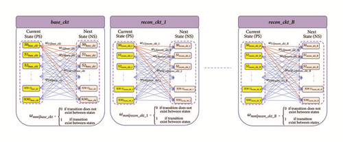
In FSM implementation on an FPGA platform, state encoding technique acts as a tool for minimizing the hardware consumption [9, 10]. For example, an MCNC FSM benchmark tbk requires 82 LUTs when implemented on a Xilinx xc6vlx75t-3 device (Virtex-6) using the Grey encoding technique. But it needs only 41 LUTs on the same platform using the binary encoding technique.
The major problem concerning IGHA is the disintegration of a state encoding technique. It uses binary state encoding as a default state assignment technique for operation [6]. The state assignment method for the Reconfigurable FSMIM architecture leads to an optimization problem as evident from Figure 1. To the best of the authors’ knowledge, all the state assignment techniques proposed in the literature provide state codes only for a single FSM.
Therefore, the objective of this work is the integration of IGHA with an optimal state encoding technique to reduce the hardware consumption of Reconfigurable FSMIM on an FPGA platform.
3. Methodology
This work is an extension of work presented in [6]. Hence, all the variables from [6] are used in the same context throughout the article. An improved version of IGHA (Improved-IGHA) is proposed. It addresses the issue of optimal state encoding.
A recent body of literature has investigated the performance of three fundamental types of state encoding techniques on an FPGA platform [9]. The studied methods are as follows: (a) structural approaches, (b) heuristic approaches, and (c) pragmatic approaches. Out of these three approaches, structural state encoding technique outperforms on an FPGA platform [9, 10]. It uses the knowledge of internal structure (i.e., state transition) of the FSM to generate optimal state codes. Therefore, structural information of FSMs is considered to develop the proposed state encoding technique for the Reconfigurable FSMIM.
The structural information of the Reconfigurable FSMIM (i.e., state transition) is obtained from Figure 1. Hence, a unified weight matrix is defined by adding the weight of all component FSMs for the same corresponding states. It is given in (1).
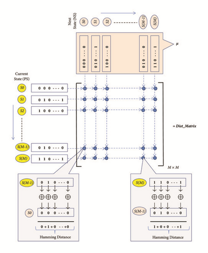
3.1. State Assignment Using Logarithmic Barrier Function Based Gradient Descent Approach for the Reconfigurable FSM
Let the graph described by (2) be Gmap = (Vmap, Emap), where Emap ( i.e., ωij) indicates the edge weights between the nodes & Vmap ( i.e., columns of μ) represents the set of nodes. Hence, each node corresponds to a particular binary state code because μij opts only the binary labels. M symbolizes the total number of nodes in the graph Gmap.
The objective is thus confined to minimize the cost function given in (7). Evidently, it is a discrete optimization problem, where each state can opt only a particular binary state code.
The convergence of Improved-IGHA depends on the convergence of its constituent algorithms, i.e., IGHA and the applied state assignment technique. Therefore, an algorithm with a high convergence speed is preferred to construct the state assignment technique for Improved-IGHA.
The evolutionary technique, such as genetic algorithm (GA), presents a significant shortcoming as its convergence speed slows down near the global optimum [18, 19]. Similarly, particle swarm optimization (PSO) and differential evolution (DE) operate with a high convergence rate but offer premature convergence which is a critical drawback [20, 21]. In the literature, penalty-based approaches, such as Lagrangian technique and logarithmic-barrier function (LBF) method, have proven their potentials to obtain the optimum solution with a high convergence speed [22, 23]. These methods are advantageous in solving a discrete or combinatorial optimization problem [24, 25].
Therefore, the LBF-based Gradient descent approach is adopted to construct the state assignment technique for Improved-IGHA. It is an interior point method that assures the feasible solution. The mathematical formulation of the cost minimization function is performed by LBF. Then, it is reduced iteratively by the gradient-projection approach. The flow chart for the Improved-IGHA is presented in Figure 3.
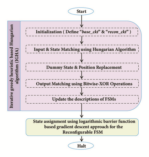
In LBF technique, the search operation is performed in a continuous space domain to deduce the optimal points. Then, these points are discretized to obtain the optimal solution [26, 27].
Initially, LBF selects a feasible τ0 and ϕ0 > 0. Then, it chooses ϕiter_t+1 = σ · ϕiter_t, where σ < 1. This iterative process goes on until ϕiter_t reaches an adequately small value.
The pseudocode for the proposed state assignment approach is presented in Algorithm 1.
-
Algorithm 1: State assignment using logarithmic barrier-function based gradient descent approach for the Reconfigurable FSM.
-
Input:the objective function defined by Equation (7)
-
Output:μ∗ (i.e., the final state code vector)
-
-
begin
-
Initialization: μ ← Binary state codes;
-
ϕ ← initial_ϕ (s.t. ϕ0 > 0);
-
while (ϕ > final_ϕ)do
-
repeat
-
for iter_t ← 1 to θ
-
τiter_t ← τ(iter_t−1)
-
−ρ{∇ψ(τ, ϕ)};
-
/∗by Equation (12)
-
& Equation (24)∗/
-
end
-
return
-
at the iteration θ);
-
evaluate
-
/∗by Equation (26)∗/
-
Compute cost for the new value of μ
-
using Equation (7);
-
if (cost(old_μ)
-
≥cost(new_μ))then
-
update, μ∗ ← new_μ;
-
else if (cost(old_μ)
-
<cost(new_μ))then
-
update, μ∗ ← old_μ;
-
end
-
untilthe algorithm converges
-
ϕ ← σ · ϕ;
-
end
-
returnμ∗;
-
end
3.2. An Illustrative Example for the Improved Reconfigurable FSMIM Architecture
| Input | PS | NS | O/P | |
|---|---|---|---|---|
| x1 | x2 | y1 | ||
| 0 | 0 | S0 | S0 | 0 |
| 1 | 0 | S0 | S1 | - |
| 0 | 1 | S0 | S2 | - |
| 1 | 0 | S1 | S1 | 1 |
| 0 | 0 | S1 | S3 | 1 |
| 1 | 1 | S1 | S5 | 1 |
| 0 | 1 | S2 | S2 | 1 |
| 0 | 0 | S2 | S7 | 1 |
| 1 | 1 | S2 | S9 | 1 |
| 0 | 0 | S3 | S3 | 1 |
| 0 | 1 | S3 | S4 | 1 |
| 0 | 1 | S4 | S4 | 1 |
| 0 | 0 | S4 | S0 | - |
| 1 | 1 | S5 | S5 | 1 |
| 0 | 1 | S5 | S6 | 1 |
| 0 | 1 | S6 | S6 | 1 |
| 0 | 0 | S6 | S0 | - |
| 0 | 0 | S7 | S7 | 1 |
| 1 | 0 | S7 | S8 | 1 |
| 1 | 0 | S8 | S8 | 1 |
| 0 | 0 | S8 | S0 | - |
| 1 | 1 | S9 | S9 | 1 |
| 1 | 0 | S9 | S10 | 1 |
| 1 | 0 | S10 | S10 | 1 |
| 0 | 0 | S10 | S0 | - |
| Input | PS | NS | O/P | |
|---|---|---|---|---|
| x1 | x2 | y1 | ||
| 1 | 0 | S0 | S1 | 0 |
| 0 | 0 | S0 | S0 | 0 |
| 0 | 0 | S1 | S0 | 0 |
| 1 | 0 | S1 | S1 | 0 |
| 1 | 1 | S1 | S2 | 0 |
| 1 | 0 | S2 | S1 | 0 |
| 1 | 1 | S2 | S2 | 0 |
| 0 | 1 | S2 | S3 | 0 |
| 1 | 1 | S3 | S2 | 1 |
| 0 | 1 | S3 | S3 | 1 |
| 0 | 0 | S3 | S4 | 1 |
| 0 | 1 | S4 | S3 | 1 |
| 0 | 0 | S4 | S4 | 1 |
| 1 | 0 | S4 | S5 | 1 |
| 0 | 0 | S5 | S4 | 1 |
| 1 | 0 | S5 | S5 | 1 |
| 1 | 1 | S5 | S6 | 1 |
| 1 | 0 | S6 | S5 | 1 |
| 1 | 1 | S6 | S6 | 1 |
| 0 | 1 | S6 | S7 | 1 |
| 1 | 1 | S7 | S6 | 1 |
| 0 | 1 | S7 | S7 | 1 |
| 0 | 0 | S7 | S8 | 1 |
| 0 | 1 | S8 | S7 | 1 |
| 0 | 0 | S8 | S8 | 1 |
- (i)
Initialization (Define base_ckt and recon_ckt): train11 is selected as base_ckt because its complexity is greater than lion9 as observed from their descriptions. Consequently, lion9 acts as recon_ckt.
- (ii)
Input and State Matching using Hungarian Algorithm: Input and state matchings are performed together using Algorithms 1, 2, 5, and 6 from [6]. Combinations of input lines of base_ckt (i.e., 2P2 = 2) are generated. For the first combination (x1∣train11, x2∣train11), states are matched as S0lion9 → S0train11, S1lion9 → S1train11, S3lion9 → S2train11, S4lion9 → S3train11, S7lion9 → S4train11, S2lion9 → S5train11, S8lion9 → S6train11, S5lion9 → S7train11, Dummy state → S8train11, S6lion9 → S9train11, and Dummy state → S10train11. It offers zero assignment_cost and total_cost. For the second combination (x2∣train11, x1∣train11), states are matched as S0lion9 → S0train11, S3lion9 → S1train11, S1lion9 → S2train11, S4lion9 → S3train11, S5lion9 → S4train11, S2lion9 → S5train11, Dummy state → S6train11, S7lion9 → S7train11, S8lion9 → S8train11, S6lion9 → S9train11, and Dummy state → S10train11. It also offers zero assignment_cost and total_cost. Therefore, the first combination (x1∣train11, x2∣train11) is finalized to match with (x1∣lion9, x2∣lion9).
- (iii)
Dummy State and Position Replacement: The replacements of the dummy states and positions in base_ckt and recon_ckt are performed using Algorithm 3 from [6]. The replaced dummy states (highlighted in “bold italic font”) and dummy positions (highlighted in “bold font”) are presented in Tables 3 and 4.
- (iv)
Output Matching using Bitwise-XOR Operations: Output Matching is not required in this case, as there is a single output line in base_ckt as well as in recon_ckt.
- (v)
Update the descriptions of FSMs: The updated descriptions of base_ckt and recon_ckt are presented in Tables 3 and 4, respectively.
- (vi)
State assignment using logarithmic barrier function based gradient descent approach for the Reconfigurable FSM: The pictorial representation of state transitions for base_ckt and recon_ckt (from Tables 3 and 4) is given in Figure 4. Therefore, the weight matrix ω is formed using (1). It is given in
(27) -
The proposed state assignment algorithm starts by considering the binary state codes as an initial solution. It offers the cost as 62 (from (2)).
-
At the 100th iteration, the instantaneous value τ (from previous iteration, τ(iter_99)) is obtained as defined by
(28) -
The derivative (from (24)) is evaluated as defined by
(29) -
So, the current value of τ (i.e., τ(iter_100)) is obtained from (12). It is given in (30) by choosing ρ = 10−3 (a very small value).
(30) -
Then, τ is directed towards the unity radius hypersphere. It is given in
(31) -
The required set of state codes is deduced as S0 → 1110, S1 → 1010, S2 → 0000, S3 → 1000, S4 → 0100, S5 → 0010, S6 → 0110, S7 → 1001, S8 → 1101, S9 → 0001, and S10 → 1100 by discretizing the current value of τ using (26). Hence, the cost is reduced to 48 (from (2)).
| Input | PS | NS | O/P | |
|---|---|---|---|---|
| x1 | x2 | y1 | ||
| 0 | 0 | S0 | S0 | 0 |
| 1 | 0 | S0 | S1 | - |
| 0 | 1 | S0 | S2 | - |
| 1 | 0 | S1 | S1 | 1 |
| 0 | 0 | S1 | S3 | 1 |
| 1 | 1 | S1 | S5 | 1 |
| 0 | 1 | S2 | S2 | 1 |
| 0 | 0 | S2 | S7 | 1 |
| 1 | 1 | S2 | S9 | 1 |
| 0 | 0 | S3 | S3 | 1 |
| 0 | 1 | S3 | S4 | 1 |
| 0 | 0 | S3 | S3 | 1 |
| 0 | 1 | S4 | S4 | 1 |
| 0 | 0 | S4 | S0 | - |
| 0 | 1 | S4 | S4 | 1 |
| 1 | 1 | S5 | S5 | 1 |
| 0 | 1 | S5 | S6 | 1 |
| 1 | 1 | S5 | S5 | 1 |
| 0 | 1 | S6 | S6 | 1 |
| 0 | 0 | S6 | S0 | - |
| 0 | 0 | S7 | S7 | 1 |
| 1 | 0 | S7 | S8 | 1 |
| 1 | 0 | S7 | S8 | 1 |
| 1 | 0 | S8 | S8 | 1 |
| 0 | 0 | S8 | S0 | - |
| 0 | 0 | S8 | S0 | - |
| 1 | 1 | S9 | S9 | 1 |
| 1 | 0 | S9 | S10 | 1 |
| 1 | 1 | S9 | S9 | 1 |
| 1 | 0 | S10 | S10 | 1 |
| 0 | 0 | S10 | S0 | - |
| 0 | 0 | S10 | S0 | - |
| Input | PS | NS | O/P | |
|---|---|---|---|---|
| x1 | x2 | y1 | ||
| 0 | 0 | S0 | S0 | 0 |
| 1 | 0 | S0 | S1 | 0 |
| 0 | 0 | S0 | S0 | 0 |
| 1 | 0 | S1 | S1 | 0 |
| 0 | 0 | S1 | S0 | 0 |
| 1 | 1 | S1 | S5 | 0 |
| 0 | 1 | S2 | S2 | 1 |
| 0 | 0 | S2 | S3 | 1 |
| 1 | 1 | S2 | S5 | 1 |
| 0 | 0 | S3 | S3 | 1 |
| 0 | 1 | S3 | S2 | 1 |
| 1 | 0 | S3 | S7 | 1 |
| 0 | 1 | S4 | S4 | 1 |
| 0 | 0 | S4 | S6 | 1 |
| 1 | 1 | S4 | S9 | 1 |
| 1 | 1 | S5 | S5 | 0 |
| 0 | 1 | S5 | S2 | 0 |
| 1 | 0 | S5 | S1 | 0 |
| 0 | 1 | S6 | S4 | 1 |
| 0 | 0 | S6 | S6 | 1 |
| 0 | 0 | S7 | S3 | 1 |
| 1 | 0 | S7 | S7 | 1 |
| 1 | 1 | S7 | S9 | 1 |
| 1 | 0 | S8 | S1 | 0 |
| 0 | 0 | S8 | S0 | 0 |
| 0 | 0 | S8 | S0 | 0 |
| 1 | 1 | S9 | S9 | 1 |
| 1 | 0 | S9 | S7 | 1 |
| 0 | 1 | S9 | S4 | 1 |
| 1 | 0 | S10 | S1 | 0 |
| 0 | 0 | S10 | S0 | 0 |
| 0 | 0 | S10 | S0 | 0 |
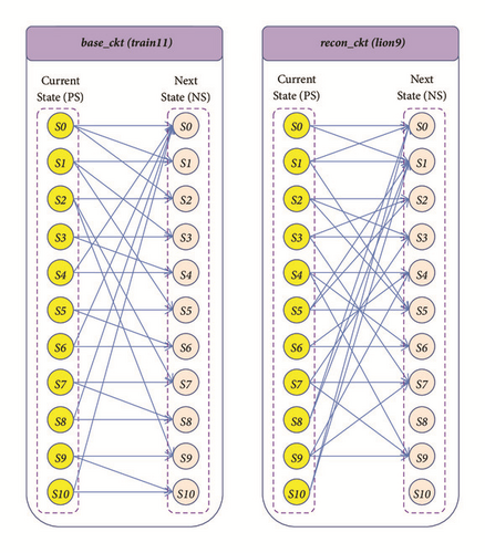
In the end, a Bitwise-XOR operation is performed between the updated descriptions of train11 and lion9. It provides the Multiplexer bank (i.e., part-B). The updated descriptions of train11 are used to construct the Conventional FSMIM part (i.e., part-A).
4. Numerical Results and Discussions
To validate the proposed approach, experiments have been performed using MCNC FSM benchmarks [14]. MATLAB (2016b) environment is used to implement the proposed Improved-IGHA. It produces the optimized description for the constituting parts of the Improved Reconfigurable FSMIM architecture. The obtained description is then converted into the Verilog HDL code using MATLAB HDL Coder tool-box. The implementation of the Improved Reconfigurable FSMIM architecture is performed on the Virtex-6 speed-3 device as in [6, 11]. The configuration of the workstation to execute computations is as follows: Intel(R) Core i7 (6th Gen), 16 GB RAM, and 3.5 GHz CPU.
In Improved-IGHA, combinations of input lines, states, and output lines are generated using permutation to perform input, state, and output matching, respectively. The number of input and output lines used for matching is restricted to 7 (i.e., 7P7 = 5040 combinations) to utilize the resources efficiently. Hence, the information content of an input/output line becomes the criteria for selection. An input/output line with high information content is preferred.
The following MCNC FSM benchmarks [14] are selected to illustrate the implementation of the Improved Reconfigurable FSMIM architecture and present its comparative analysis with the existing literature: s1494, s832, s208, planet, s386, sand, mc, styr, cse, ex6, planet1, and s1488.
s1494 is chosen as base_ckt (i.e., the circuit added at the 0th iteration of Improved-IGHA), as it is more complex (i.e., the total number of transitions is high) as compared with the other FSMs in the set. The other FSMs in the set are added iteratively in the design in their respective order.
In an FSM, a specific state is chosen only if a particular set of input bits (i.e., 1’s or 0’s) are present. Hence, the percentage of 1’s and 0’s together in an input line acts as information content as shown in Table 5 (the selected input lines to match with base_ckt are highlighted). Similarly, the output is always defined by “1.” Hence, the percentage of 1’s in an output line serves as information content as shown in Tables 6 and 7 (the selected output lines to match with base_ckt are highlighted).
| FSM | No. of I/P | Input lines with their | Matched with base_ckt | No. of state |
|---|---|---|---|---|
| information content | ||||
| s1494 | 8 | x1(99.6%), x2(10%), | x1, x3, | 48 |
| x3(25.6%), x4(24.8%), | x4, x5, | |||
| x5(12.4%), x6(66%), | x6, x7, | |||
| x7(41.6%), x8(20.4%) | x8 | |||
| s832 | 18 | x1(2.04%), x2(6.93%), | 25 | |
| x3(2.44%), x4(4.48%), | ||||
| x5(70.61%), x6(1.63%), | ||||
| x7(14.28%), x8(9.79%), | x9, x11, | |||
| x9(8.97%), x10(8.16%), | x18, x17, | |||
| x11(8.57%), x12(6.12%), | x8, x7, x5 | |||
| x13(4.081%), x14(4.08%), | ||||
| x15(1.63%), x16(1.63%), | ||||
| x17(59.18%), x18(81.63%), | ||||
| s208 | 11 | x1(96.73%), x2(91.5%), | 18 | |
| x3(0%), x4(0%), | x1, x8, | |||
| x5(0%), x6(2.61%), | x6, x9, | |||
| x7(2.61%), x8(5.22%), | x11, x2, | |||
| x9(12.41%), x10(49.01%), | x10 | |||
| x11(77.12%) | ||||
| planet | 7 | x1, x2, | x6, x3, | 48 |
| x3, x4, | x4, x2, | |||
| x5, x6, | x5, x7, | |||
| x7 | x1 | |||
| s386 | 7 | x1, x2, | x4, x3, | 13 |
| x3, x4, | x2, x7, | |||
| x5, x6, | x1, x5, | |||
| x7 | x6 | |||
| sand | 11 | x1(52.17%), x2(52.17%), | 32 | |
| x3(52.17%), x4(52.17%), | x4, x2, | |||
| x5(24.45%), x6(3.26%), | x1, x10, | |||
| x7(18.47%), x8(26.63%), | x5, x3, | |||
| x9(1.08%), x10(79.89%), | x8 | |||
| x11(19.56%) | ||||
| mc | 3 | −, x3, | 4 | |
| x1, x2, | x1,−, | |||
| x3 | x2, −, | |||
| − | ||||
| styr | 9 | x1(92.16%), x2(4.81%), | 30 | |
| x3(48.79%), x4(69.87%), | x2, x4, | |||
| x5(68.67%), x6(39.15%), | x5, x3, | |||
| x7(4.81%), x8(5.42%), | x8, x6, x1 | |||
| x9(3.61%) | ||||
| cse | 7 | x1, x2, | x5, x2, | 16 |
| x3, x4, | x7, x3, | |||
| x5, x6, | x4, x1, | |||
| x7 | x6 | |||
| ex6 | 5 | x3, x4, | 8 | |
| x1, x2, | −, x1, | |||
| x3, x4, x5 | x2, −, | |||
| x5 | ||||
| planet1 | 7 | x1, x2, | x5, x1, | 48 |
| x3, x4, | x6, x3, | |||
| x5, x6, | x4, x2, | |||
| x7 | x7 | |||
| s1488 | 8 | x1(98.8%), x2(12.74%), | x1, x5, | 48 |
| x3(23.5%), x4(23.9%), | x3, x4, | |||
| x5(16.33%), x6(65.73%), | x8, x7, | |||
| x7(40.23%), x8(18.32%) | x6 | |||
| FSM | No. of O/P | Output lines with their | Matched with base_ckt |
|---|---|---|---|
| information content | |||
| s1494 | 19 | y1(24.8%), y2(4.8%), y3(5.2%), | |
| y4(3.2%), y5(2.4%), y6(2.4%), | y11, y12, | ||
| y7(15.2%), y8(25.2%), y9(1.6%), | y13, y14, | ||
| y10(6.4%), y11(87.2%), y12(40.4%), | y15, y17, | ||
| y13(32.8%), y14(70.4%), y15(38.4%), | y19 | ||
| y16(18.4%), y17(70%), y18(31.2%), | |||
| y19(49.2%) | |||
| s832 | 19 | y1(5.71%), y2(2.44%), y3(1.22%), | |
| y4(1.63%), y5(2.44%), y6(0.81%), | y19, y15, | ||
| y7(2.44%), y8(73.06%), y9(0.81%), | y2, y8, | ||
| y10(0.81%), y11(5.3%), y12(2.44%), | y7, y1, | ||
| y13(0.81%), y14(1.63%), y15(6.12%), | y11 | ||
| y16(0.81%), y17(1.63%), y18(2.44%), | |||
| y19(41.22%) | |||
| s208 | 2 | y1, y2 | −, y1, |
| −, −, | |||
| y2, −, | |||
| − | |||
| planet | 19 | y1(54.78%), y2(23.47%), y3(69.56%), | |
| y4(16.52%), y5(32.17%), y6(73.91%), | y6, y8, | ||
| y7(26.08%), y8(28.69%), y9(91.3%), | y9, y5, | ||
| y10(4.34%), y11(1.73%), y12(22.6%), | y3, y1, | ||
| y13(11.3%), y14(2.6%), y15(3.47%), | y7 | ||
| y16(1.73%), y17(3.47%), y18(3.47%), | |||
| y19(20%) | |||
| s386 | 7 | y6, y1, | |
| y1, y2, y3, | y3, y4, | ||
| y4, y5, y6, y7 | y7, y5, | ||
| y2 | |||
| sand | 9 | y1(22.28%), y2(36.41%), y3(16.84%), | y4, y6, |
| y4(62.5%), y5(15.76%), y6(8.15%), | y2, y7, | ||
| y7(17.39%), y8(1.63%), y9(3.26%) | y3, y5, y1 | ||
| mc | 5 | y4, y2, | |
| y1, y2, y3, | y5, y1, | ||
| y4, y5 | y3, −, | ||
| − | |||
| styr | 10 | y1(15.66%), y2(33.73%), y3(25.9%), | y5, y6, |
| y4(3.012%), y5(8.43%), y6(7.22%), | y7, y8, | ||
| y7(5.42%), y8(11.445%), y9(3.614%), | y3, y2, | ||
| y10(4.819%) | y1 | ||
| cse | 7 | y7, y3, | |
| y1, y2, y3, | y5, y1, | ||
| y4, y5, y6, y7 | y4, y6, | ||
| y2 | |||
| ex6 | 8 | y1(58.82%), y2(29.41%), y3(55.88%), | y5, y8, |
| y4(29.41%), y5(50%), y6(26.47%), | y4, y1, | ||
| y7(5.88%), y8(23.52%) | y6, y2, y3 | ||
| FSM | No. of O/P | Output lines with their | Matched with base_ckt |
|---|---|---|---|
| information content | |||
| planet1 | 19 | y1(54.78%), y2(23.47%), y3(69.56%), | |
| y4(16.52%), y5(32.17%), y6(73.91%), | y6, y7, | ||
| y7(26.08%), y8(28.69%), y9(91.3%), | y1, y8, | ||
| y10(4.34%), y11(1.73%), y12(22.6%), | y5, y3, | ||
| y13(11.3%), y14(2.6%), y15(3.47%), | y9 | ||
| y16(1.73%), y17(3.47%), y18(3.47%), | |||
| y19(20%) | |||
| s1488 | 19 | y1(2.39%), y2(2.78%), y3(1.59%), | |
| y4(5.17%), y5(2.39%), y6(15.13%), | y18, y7, | ||
| y7(71.31%), y8(3.98%), y9(51.39%), | y13, y19, | ||
| y10(6.3%), y11(16.7%), y12(37.1%), | y9, y15, | ||
| y13(70.5%), y14(24.3%), y15(87.6%), | y12 | ||
| y16(31.1%), y17(25.4%), y18(31.4%), | |||
| y19(39.84%) | |||
At the first phase of Improved-IGHA, input and state matching are performed together, and optimal assignments (with respect to base_ckt) are made. It is presented in Table 5. All the recon_ckt states are mapped onto base_ckt states in their respective order. Output matching (with respect to base_ckt) is performed iteratively by Bitwise-XOR operations. It is presented in Tables 6 and 7. Then, after updating the descriptions of constituting FSMs, the state assignment using logarithmic barrier function based gradient descent approach is performed.
| Iteration No. | FSM included | Total elapsed time | Total elapsed time | Total elapsed time for Improved-IGHA |
|---|---|---|---|---|
| in the specific | for IGHA [6] | for state encoding | (Hrs) tProposed = tIG + tSE | |
| iteration | (Hrs) tIG | tech. (ms) tSE | ∵tIG ≫ tSE, ∴tProposed≅tIG | |
| 0th | s1494 | 0 | 296.529 | 0 |
| 1st | s832 | 25.34 | 214.468 | 25.34 |
| 2nd | s208 | 18.57 | 156.062 | 18.57 |
| 3rd | planet | 48.65 | 338.560 | 48.65 |
| 4th | s386 | 13.17 | 182.808 | 13.17 |
| 5th | sand | 32.43 | 293.894 | 32.43 |
| 6th | mc | 0.182 | 148.784 | 0.182 |
| 7th | styr | 30.409 | 249.509 | 30.409 |
| 8th | cse | 16.21 | 387.923 | 16.21 |
| 9th | ex6 | 4.38 | 167.144 | 4.38 |
| 10th | planet1 | 48.544 | 312.809 | 48.544 |
| 11th | s1488 | 48.654 | 326.406 | 48.654 |
The experimental results presented in Table 8 illustrate that the total computation time required by IGHA is far higher than the convergence time for the proposed state assignment technique (i.e., tIG ≫ tSE). Therefore, the total computation time required by Improved-IGHA is equivalent to the total computation time needed by IGHA (i.e., tProposed≅tIG).
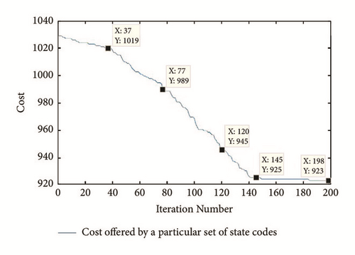
Convergence plot for the state assignment using logarithmic barrier function based gradient descent approach after adding the last constituting FSM in the proposed architecture is presented in Figure 5. It starts by taking binary state codes as an initial code. The cost offered to the proposed architecture is calculated by (2). It converges to 200 iterations. The cost is reduced from 1028 to 923 as shown in Figure 5. Consequently, at 200th iteration, the following state codes are obtained: S0 → 010111, S1 → 000000, S2 → 000111, S3 → 110000, S4 → 010100, S5 → 110101, S6 → 000110, S7 → 011101, S8 → 001100, S9 → 011010, S10 → 011110, S11 → 001110, S12 → 010110, S13 → 111011, S14 → 000011, S15 → 100110, S16 → 110111, S17 → 001010, S18 → 011100, S19 → 100001, S20 → 101001, S21 → 110010, S22 → 100000, S23 → 001000, S24 → 001111, S25 → 101101, S26 → 010011, S27 → 101010, S28 → 110001, S29 → 001011, S30 → 111010, S31 → 011111, S32 → 000101, S33 → 000100, S34 → 111101, S35 → 000001, S36 → 001101, S37 → 101000, S38 → 000010, S39 → 100111, S40 → 110110, S41 → 011001, S42 → 100010, S43 → 001001, S44 → 010001, S45 → 100101, S46 → 101111, and S47 → 010010.
At the last phase of Improved-IGHA, a mutual Bitwise-XOR operation is conducted between the updated descriptions of FSMs. Therefore, the constituting parts of the proposed architecture are created. The individual share of constituent FSMs in the Improved-Reconfigurable FSMIM architecture is determined by the difference between the occupied LUTs in the recent and its previous iteration. After adding all the constituting FSMs in the proposed design (i.e., at the last iteration), the total LUT consumption and operating frequency are obtained. It is presented in Table 9.
| Iteration No. | FSM included | #LUTs occupied | Maximum | Maximum | #LUTs occupied by the FSM |
|---|---|---|---|---|---|
| in the specific | in the specific | Operating | Path | (#LUTs in the current iteration | |
| iteration | iteration | Frequency (MHz) | Delay (ns) | - #LUTs in the previous iteration) | |
| 0th | s1494 | 40 | 831.693 | 3.898 | 40 |
| 1st | s832 | 97 | 803.44 | 4.288 | 57 |
| 2nd | s208 | 114 | 793.583 | 5.252 | 17 |
| 3rd | planet | 142 | 785.326 | 4.219 | 28 |
| 4th | s386 | 157 | 776.863 | 4.534 | 15 |
| 5th | sand | 187 | 760.88 | 4.117 | 30 |
| 6th | mc | 198 | 757.237 | 3.854 | 11 |
| 7th | styr | 217 | 743.431 | 4.204 | 19 |
| 8th | cse | 240 | 713.929 | 4.401 | 23 |
| 9th | ex6 | 249 | 704.892 | 4.649 | 9 |
| 10th | planet1 | 274 | 690.83 | 4.977 | 25 |
| 11th | s1488 | 293 | 676.928 | 5.151 | 19 |
- #LUTs → number of LUTs occupied in ISE
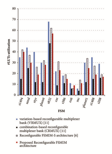
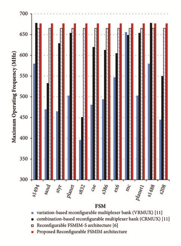
Experimental results for the proposed architecture illustrates a significant area reduction by an average of 20.38% and speed improvement by an average of 32.73% over VRMUX [11] during FPGA implementation. It also demonstrates an adequate area reduction by an average of 16.05% and speed improvement by an average of 1.77% over Reconfigurable FSMIM-S architecture [6] during FPGA implementation. When these results are compared with CRMUX [11], a speed improvement by an average of 11.06% is obtained. The proposed architecture requires an average of 58.38% more LUTs as compared with CRMUX [11] during FPGA implementation. It is the only trade-off for the proposed design. A comparative analysis of the hardware consumption and maximum operating frequency variation on FPGA implementation is presented in Figures 6 and 7, respectively.
5. Concluding Remarks
This article furnishes the framework for the Improved-Reconfigurable FSMIM architecture. The Improved-Reconfigurable FSMIM architecture is created by joining the following two parts: (A) Conventional FSMIM architecture and (B) Multiplexer bank (which defines the mode based reconfiguration). An improved version of iterative greedy heuristic based Hungarian algorithm (Improved-IGHA) is proposed to establish the constituting parts as mentioned earlier. Improved-IGHA is an integration of IGHA [6] and a state assignment using logarithmic barrier function based gradient descent approach. It reduces the hardware consumption of the proposed architecture by performing an optimal state encoding. An illustrative example using MCNC FSM benchmarks is also given to demonstrate the steps involved in the creation of the proposed architecture.
The proposed architecture illustrates a significant area reduction by an average of 20.38% and speed improvement by an average of 32.73% over VRMUX [11] during FPGA implementation. It also demonstrates an adequate area reduction by an average of 16.05% and speed improvement by an average of 1.77% over Reconfigurable FSMIM-S architecture [6] during FPGA implementation. When these results are compared with CRMUX [11], a speed improvement by an average of 11.06% is obtained. The proposed architecture requires an average of 58.38% more LUTs as compared with CRMUX [11] during FPGA implementation. It is the only trade-off for the proposed design.
Further, the proposed architecture will be investigated to develop an efficient architecture for multistage signal processing [1, 2] and circuit testing [5] based applications.
Conflicts of Interest
The authors declare that they have no conflicts of interest.
Acknowledgments
The datasets generated during and/or analyzed during the current study are available in [6] repository [DOI: 10.1155/2018/6831901]. This work is conducted in the Department of ECE, SRM Institute of Science and Technology, Kattankulathur-603203, Chennai, India.
Open Research
Data Availability
The data used to support the findings of this study are available from the corresponding author upon request.


