Nanofiber-Coated CF/PEEK Composite: Boosting Osteogenesis for Enhanced Bone Grafting
Abstract
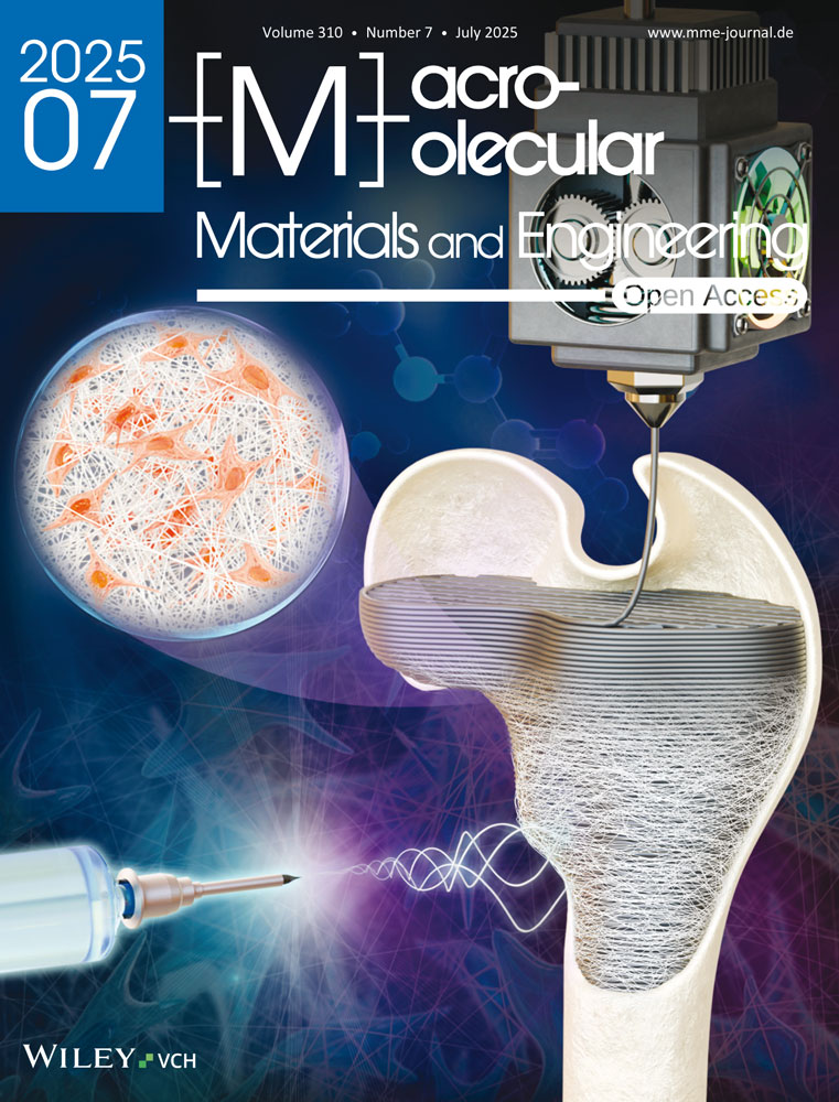
This study presents the fabrication of carbon-fiber-reinforced polyetheretherketone (CF/PEEK) by 3D printing, which is subsequently coated with elastic nanofibers by electrospinning. CF/PEEK is an FDA-approved implantable material possessing excellent mechanical properties similar to those of human cortical bone. As such, it is a prime candidate for replacing conventional metallic implants. However, it is limited by its bioinertness and inferior osteogenic properties. In this study, CF/PEEK is engineered to have improved hydrophilic properties and generated micro/nano-topographical structures on its surface. This is achieved by electrospinning directly onto the 3D-printed CF/PEEK with fibers incorporating hydroxyapatite particles and gelatin. The results show that the micro-/nano-topographical CF/PEEK demonstrates a significant increase in mineralizing potential compared to non-coated implants, where no mineralized matrix is observed. These fiber coating modifications to CF/PEEK are a promising and important step forward in the improvement of in vivo implant-bone osteointegration.
1 Introduction
Following skeletal trauma, an autologous bone graft offers an opportunity for new, healthy bone to repair the damaged site, using the patient's own bone as a scaffold.[1] For a myriad of reasons, such grafts are often not an option, and in these situations, synthetic compounds such as titanium or polyetheretherketone (PEEK) offer an important alternative.[2-4] However, it is imperative that these alternatives do not impede the healing or impinge on the requisite biomechanical properties of bone. Titanium, for example, has fallen out of favor in recent years due to its poor wear and propensity for bone absorption.[5, 6]
Underlying the effectiveness of any graft are the biological properties of bone. Bone is a dynamic tissue, continually being remodeled to remove small microcracks in order to maintain optimum bone health.[7] Osteoblasts secrete and lay down a collagen-rich extracellular matrix (ECM), the scaffold on which bone is built. On this scaffold, stiffness is conferred by the biomineralization process, in which carbon-substituted hydroxyapatite (HA) is incorporated into the ECM by osteoblast activity.[8, 9] This forms a two-phase composite material with stiff and tough properties that provide resistance to fracture.[10] Bone health is monitored by osteocytes, differentiated osteoblasts embedded within the ECM, which, through their dendritic processes, communicate to both osteoblasts and osteoclasts to coordinate the bone remodeling process.[11] Therefore, for an implant to be successful, it must provide a biologically sound scaffold for these events to take place.
Structurally represented as (─C6H4─OC6H4─O─C6H4─CO─)n, PEEK is a semi-crystalline polymer that has seen an increasing trend in the development of medical devices because of its desirable properties including, but not limited to, stiffness, toughness, mechanical strength, radiolucency, biocompatibility, and stability.[12-14] The mechanical strength, thermal stability, and chemical resistance of PEEK can be further improved by the incorporation of carbon fibers (CF). The elastic modulus of carbon-fiber-reinforced PEEK (CF/PEEK) is close to that of human cortical bone (18 GPa),[15] making it a promising alternative to metallic implants, which have much higher elastic modulus (110 GPA).[16]
Additive manufacturing technology is a layer-by-layer manufacturing method that allows the fabrication of polymer-based components of different shapes from digital computer models.[17] This avoids the need for costly tools and workpiece fabrication while fitting the shapes of different bone defects, producing near-net-shape objects, and minimizing the demand for further processing.[18] Biomedical implants are usually of a size within the range of most commercial 3D printers, meaning highly customized and tailored parts can be manufactured using 3D printing.[19] PEEK and its composites have become research hotspots in the 3D printing field. However, because of the high melting point, the thermal stability of PEEK during printing should be improved. Therefore, Wang et al.,[20] added carbon fiber into PEEK and demonstrated that the addition of carbon fiber can not only improve the melting temperature and crystallization temperature of PEEK but also enhance the tensile and flexural strength, improve surface quality, reduce the porosity of printed CF/PEEK.
Although the CF/PEEK has attracted much attention as orthopedic implants, the bioinert properties of this material hampers osteointegration after implantation, thereby severely impeding clinical adoption.[21] Surface topographical modification is an effective way to confer biological properties while preserving the advantageous properties of the core materials.[21, 22] By introducing bioactive materials, such as HA and gelatin, the cytocompatibility can be significantly improved.[23-25] The bioactive material should be evenly distributed on the CF/PEEK to achieve optimum biocompatibility. Electrospinning is a simple and versatile method that can create fibers covering the target materials for surface modification.[26] Adding bioactive nanoparticles (NPs) with good dispersibility to the electrospinning solution allows an even distribution of the NPs in the electrospun fibers, thus evenly distributing them on the target materials.[27, 28]
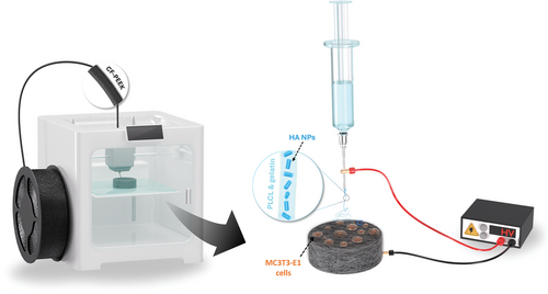
This paper investigates the enhancement of cell viability and mineralization potential of 3D-printed CF/PEEK implants by using electrospinning technology (Figure 1). Poly(L-lactide-co-caprolactone) (PLCL) and gelatin were applied in combination with the electrospun solution to ensure that the fibers adhere tightly to the PEEK surface and provide good hydrophilic properties. By incorporating HA NPs into the fiber coating, we aimed to induce the formation of micro/nano-topographical features on the surface of CF/PEEK to improve the remineralization performance and bioactivity. Our findings underscore the significant improvements achieved with the coated implants. Such methods are anticipated to promote enhanced osteogenesis, making CF/PEEK a more favorable material for bone grafting and tissue-engineering applications.
2 Results and Discussion
Dispersibility of HA NPs is crucial for the subsequent electrospinning process because good dispersibility of the NPs enables them to be evenly distributed on the electrospun fibers and, thus, evenly distributed on the scaffolds. To allow optimum distribution of HA NPs on the electrospun fibers and, therefore, on the scaffolds, the HA NPs must exhibit good dispersibility. To confirm the ability of the HA NPs used to disperse, TEM images were produced of HA NPs prior to the electrospinning process (Figure 2a,b). All the NPs exhibited good dispersibility and a short rod shape with a length of less than 100 nm (Figure 2b). The typical diffraction peaks, as analyzed by XRD (Figure 2c), at 2θ = 25.9°, 31.8°, 32.8°, 46.8°, 49.5°, and 53.1° are consistent with the standard card of JCPDS NO. 74–0565, which demonstrates the product is HA particles.

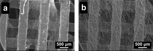
The selection of electrospinning polymers needs to consider the following requirements: the polymer(s) must be biocompatible, which is safe for human cells and tissues; the mechanical properties of the polymer fibers should not be destroyed easily to meet the operating needs; the polymer fibers should be at least partially stable in body fluid; the polymer(s) should preferably be hydrophilic to facilitate cell attachment and proliferation. There are many biocompatible polymers commonly used for electrospinning, such as polyvinyl pyrrolidone (PVP),[31] polycaprolactone (PCL),[32] and PLCL.[33] However, PVP is soluble in water, while the mechanical properties of PCL fibers are unsatisfactory. In Figure 3a, electrospun PCL fibers on 3D-printed CF/PEEK scaffolds are shown to easily break, get twisted, or shed off from the scaffold. By using PLCL fibers, it was possible to avoid these outcomes as they are elastic and can be tightly attached to the scaffold (Figure 3b).
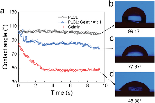
However, the water contact angle of PLCL fibers on the CF/PEEK scaffold (99.17°) shows a hydrophobic property (Figure 4b). Gelatin, as a natural macromolecule, has been proven to have many attractive properties, such as biocompatibility, biodegradability, and formability. Therefore, gelatin was added to the electrospinning solution. Water contact angles of electrospun PLCL fibers, gelatin fibers, and PLCL/gelatin fibers on 3D-printed CF/PEEK were compared (Figure 4). The CF/PEEK coated with pure PLCL fibers exhibits hydrophobic properties with a contact angle of 99.17°. The addition of gelatin significantly reduced the water contact angle (contact angle of 77.67 for a PLCL: gelatin ratio of 1:1) and changed the fiber from hydrophobic to hydrophilic, indicating an improvement in biocompatibility. Although the water contact angle of gelatin fibers (48.38°) is the minimum among the samples, due to the insufficient mechanical strength of gelatin fibers, it should be mixed with the PLCL solution to produce more appropriate blend fibers.
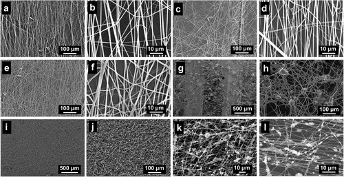
Electrospun fibers composed of PLCL and gelatin were imaged at different ratios (Figure 5). The morphology and width of the fibers (average of 700–800 nm) were similar in all PLCL:gelatin ratios examined. Given the stability of the fibers on CF/PEEK scaffolds, a ratio of PLCL:gelatin ratio of 8:2 was used for the following studies. To further enhance the biocompatibility of the fiber-coated CF/PEEK scaffolds, HA NPs were added to the PLCL/gelatin solution for uniform distribution on the scaffolds. Usually, the HA NPs are dried into powders for use.[34] However, because of their small sizes and high surface energy, NPs are easy to agglomerate. The size of aggregated particles can reach over 20 µm (Figure 5g,h), which results in increased fiber width and uneven distributions of electrospun fibers and HA particles. To avoid this problem, the HA HFP suspension instead of HA powders was mixed with the PLCL/gelatin HFP solution. Figure 5i–l reveal the resulting fibers, in which the HA NPs were uniformly distributed on the fibers, and the formation of the electrospun fibers was not influenced.
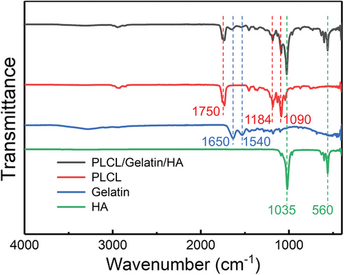
The characteristic peaks of pure PLCL, gelatin, and HA NPs are observed in the FTIR spectrum of electrospun fibers (Figure 6), demonstrating that all these distinctive features are included in the electrospun fibers. Additionally, there is no apparent change in the characteristic absorption peaks, establishing that there is almost no chemical reaction among the different components. The peaks at 1035 and 560 cm−1 could be ascribed to phosphate stretching, which are the characteristic peaks of crystalline HA particles. The typical spectral features for PLCL are the stretching vibration of C─O at 1090 and 1184 cm−1 and the ester band ─COOC─ at 1750 cm−1. The absorption peaks located at 1650 and 1540 cm−1 are amide I and II bands of the gelatin.[35, 36]
Cell toxicity was analyzed using lactate dehydrogenase activity (Figure 7a). An initial peak in cell death was identified following two days of culture (mineralization day 0) (mean = BCF = 873 RLU, HA-NF-CF/PEEK = 922 RLU). Cell death decreases significantly by day 6 of mineralization and remains below 704 RLU throughout the experiment for all conditions, confirming a lack of cytotoxicity in the HA-NF coating.
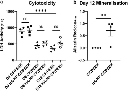
To confirm the ability of the MC3T3-E1 osteoblasts cells to mineralize their ECM in vitro, Alizarin red staining and ALP activity were measured (Figure 7b; Figure S4, Supporting Information). The ability to mineralize their matrix was increased by the implants that utilized the coating. In particular, a 7 fold increase was identified in the levels of Alizarin red bound in HA-NF-CF/PEEK implants at day 12, compared to the uncoated CF/PEEK (p = 0.0057). Alizarin red staining ARS data was supported by ALP activity, which identified a trend of increased activity in cells grown on coated implants, with the highest activity seen in cells grown on coated carbon fiber implants (Figure S4, Supporting Information). These data show that electrospun coatings do not impede bone cell differentiation and may benefit the mineralization of bone in vivo.
3 Conclusion
In this study, CF/PEEK scaffolds with micro/nano-topographical structures on their surface were obtained to improve their biocompatibility. HA NPs with a short rod shape and good dispersibility were obtained by a chemical precipitation method. PLCL was used for electrospinning to enhance the adhesion of the fibers on the CF/PEEK. The addition of gelatin in the electrospun solution changed the fiber from hydrophobic to hydrophilic. Adding HA suspension instead of dried HA particles into the electrospun solution resulted in an even distribution of HA NPs on the electrospun fiber. In vitro cell assays showed that the HA-NF-CF/PEEK inserts promote osteoblast matrix mineralization, without compromising on low levels of cytotoxicity, suggesting cells are better able to respond to the coated implants in a biologically relevant manner. We propose, therefore, that HA-NF-CF/PEEK implants offer an opportunity for improved osteointegration in the clinical setting.
4 Experimental Section
Reagents and Materials
Ca(NO3)2, (NH4)2HPO4, NH3·H2O, and 1,1,1,3,3,3-Hexafluoro-2-propanol (HFP) was bought from Alfa Aesar (China) Chemical Co Ltd. Polycaprolactone (PCL) (Average Mw = 80,000 g mol−1) and Poly (L-lactide-co-ε-caprolactone) (PLCL) (Average Mw = 67,000 g mol−1) polymers were purchased from Sigma–Aldrich, UK and Jilin Folialux Bio-Tech Company Limited, China, respectively. Gelatin was bought from Thermo Fisher Scientific (Perth, UK). α-MEM, fetal bovine serum (FBS), and gentamycin were obtained from Invitrogen (Paisley, UK). Ascorbic acid and β-glycerol phosphate (βGP) were bought from Sigma (Poole, UK). The CF/PEEK filament was purchased from Henan CreatBot Technology Ltd., China.
Preparation of HA NPs
In a typical preparation process for hydroxyapatite, 50 mL of 0.2 mol L−1 Ca(NO3)2 solution was prepared and heated to 80 °C. Thereafter, 2 mL of 10 mol L−1 NH3·H2O solution was poured into the Ca(NO3)2 solution, and 30 mL 0.2 mol L−1 (NH4)2HPO4 solution was dropped into the mixture. The reaction was allowed to proceed for 2 h at 80 °C to yield the HA precursor. The mixture was then placed in a hydrothermal reactor and heated to 200 °C for 2 h. After hydrothermal crystallization, the slurry was centrifugally washed with deionized water and ethanol several times. The HA pastes obtained after the last centrifugation were added into HFP for further application.
3D Printing of CF/PEEK
3D printing of CF/PEEK was performed using the CreatBot F430 high-temperature 3D printer (Henan Creatbot Technology Ltd., China) (Figure S1, Supporting Information). The filament used was CarbonX PEEK+CF10, sourced from 3DXtech (Grand Rapids, MI, USA), which contains 10% high-modulus chopped carbon fiber (5–10 µm diameter) in a PEEK matrix.
The extrusion temperature and bed temperature were set at 420 and 100 °C, respectively. The printing speed was set at 40 mm s−1. The width and thickness of each printing path were 0.4 and 0.1 mm, respectively. CF/PEEK discs with a diameter of 9 mm and a thickness of 2 mm were 3D printed (Figure S2, Supporting Information). The discs were designed with a hole in the middle across its diameter, which allowed the rotating metal collector to pass through the sample and hold it in place for the subsequent electrospinning process (Figure S2, Supporting Information). The mechanical properties of the used CF/PEEK are reported in Table S1 (Supporting Information) (tests were performed by the manufacturer).
Surface Modification of CF/PEEK by Electrospinning
The electrospun solutions were obtained by mixing HA HFP suspension, PLCL, and gelatin. The mass fractions of HA NPs, PLCL, and gelatin in the electrospun solution for CF/PEEK coating for cell tests were 5%, 8%, and 2%, respectively. A low-cost fused deposition modeling 3D-printed modular electrospinning setup [29] was used for electrospinning processes with a feed rate of 0.05 mL min−1 and a voltage of 15 kV. The printed disks were mounted on the rotating collector mandrel with a diameter of 0.5 mm from the side (Figure S3, Supporting Information). The mandrel was grounded via a copper cable and rotated by a 100 rpm DC motor. This enabled the 3D-printed disks to be evenly coated by the electrospun nanofibers. The nanofiber-coated CF/PEEK with HA NPs are subsequently denoted as HA-NF-CF/PEEK (Figure S3b, Supporting Information).
Characterizations
The morphology of HA NPs was obtained by transmission electron microscopy (TEM) (JEOL JEM1400 (Japan) microscope) with an accelerating voltage of 80 kV. The morphologies of electrospun fibers and surfaces of CF/PEEK and HA-NF-CF/PEEK scaffolds after cell culture were characterized by using a JEOL JSM-IT100 (Japan) scanning electron microscopy (SEM). The crystalline structure of the HA NPs was determined by an X-ray diffractometer (XRD, Bruker D8 Advance) in a 2θ range of 2.0°–60.0°. Fourier transform infrared spectroscopy (FTIR) of electrospun fibers with different components was characterized by Thermo Scientific Nicolet iS10 at the wavenumber of 4000–400 cm−1. The contact angle of different fibers was measured on the Ossila Contact Angle Goniometer; the average water droplet size is ≈0.2 µL.
Cell Viability Assays
MC3T3-E1 subclone 14 (ATCC, Virginia, USA) osteoblast-like cells were plated directly onto bare CF/PEEK, or HA-NF-CF/PEEK implants at a density of 0.066 per implant. Cells were cultured in a maintenance medium (α-MEM containing 10% (v/v) FBS and 0.05 mg mL−1 gentamycin) at 37 °C in 5% CO2 as per Huesa et al.[30] After 48 h, samples were taken for further analysis (day 0) or transferred to a mineralization medium (maintenance medium + 50 µg mL−1 ascorbic acid and 5 mM βGP) for 6–12 days.
Cell viability was analyzed at each time point (days 0, 6, and 12) via lactate dehydrogenase (LDH) activity using the LDH-Glo Cytotoxicity Assay (Promega, UK). Samples were frozen on the day of sampling, and all time points were analyzed together, as per the manufacturer's instructions.
Mineralization Assays
Cells were maintained on implants for 12 days in a mineralization medium. For Alizarin red staining, cells were fixed in 4% paraformaldehyde before staining in 2% alizarin red, pH 4.2, and destained with 10% cetylpyridium chloride. Optical density was determined at 570 nm. ALP activity was assayed from the culture medium at 12 days using an Alkaline Phosphatase Assay Kit (Colorimetric) (Abcam, UK) as per the manufacturer's instructions.
Statistical Analysis
GraphPad Prism v 9.3.1 was used for statistical analysis. Data (mean ± SEM) comparison was conducted by Mann–Whitney test or ANOVA unless otherwise stated.
Acknowledgements
D.L.Y. and L.A.S. contributed equally to this work. The authors are grateful to the China Scholarship Council for funding D-LY and to the Biotechnology and Biological Sciences Research Council (BBSRC) for supporting LAS via Discovery Fellowship (BB/X009904/1) and for Institute Strategic Programme Grant Funding (BBS/E/D/10002071 and BBS/E/RL/230001C) to the Roslin Institute which supports CF and LAS. The authors would like to thank Conchúr Ó Brádaigh of The University of Edinburgh for the access to the 3D printer and Yvonne Tusiimire of Makerere University for proofreading the manuscript. For the purpose of open access, the authors have applied a Creative Commons Attribution (CC BY) license to any Author Accepted Manuscript version arising from this submission.
Conflict of Interest
The authors declare no conflict of interest.
Open Research
Data Availability Statement
The data that support the findings of this study are available from the corresponding author upon reasonable request.


