Intraoperative assembly of anatomical shoulder prosthesis frequently results in malalignment of the modular taper junction
Abstract
Anatomical shoulder arthroplasties (ASA) may fail because of micromotion at the modular taper junction causing wear due to fretting. Sufficient taper strength can reduce micromotion and potential reasons for failure. However, there are no normative standards for a safe assembly process performed intraoperatively by the surgeon. The purpose of this study is to determine the effect of common intraoperative assembly strategies and to identify critical influencing factors on taper stability. ASA with standard and stemless humeral component in combination with concentric Al2O3 heads and eccentric CoCr28Mo6 alloyed humeral heads were tested. Taper angles and surface roughness were determined. Force magnitudes and impact directions were recorded using a sensorized head impactor and a three-dimensional force measuring platform. Subsequently, the axial pull-off forces were measured and taper engagement areas were macroscopically evaluated. In comparison to standard stem tapers that were impacted with an assembly device, stemless tapers were impacted into the artificial bone with significantly lower forces. Taper strength correlates to maximum impact force and was higher for CoCr28Mo6 heads with a mean pull-off ratio of 0.56 than for Al2O3 heads with 0.37. Interestingly, all tapers showed an asymmetric clamping behavior, due to tilting during impaction. This is caused by the variation of the resulting force vector and further promoted by humeral head eccentricity. Assembly technique markedly influences the force magnitude, impact direction, impulse, and consequently taper strength. The resulting force vector and head eccentricity were identified as potential risk factors for taper malalignment.
1 INTRODUCTION
Anatomical shoulder arthroplasties (ASA) show good outcomes for the treatment of glenohumeral joint osteoarthritis.1, 2 They aim at the restoration of the natural kinematics of the shoulder joint and to improve the patient's quality of life.3 The affected joint is replaced by insertion of a humeral stem and a connected head into the humeral bone (hemiarthroplasty) or with an additional glenoid component (total arthroplasty). The bone of the proximal humerus exhibits a large variability of geometric dimensions with respect to inclination, retroversion, and/or medial-dorsal offsets.4, 5 To allow an ideal reconstruction of the anatomical geometry and the center of rotation, a variety of implant designs and component sizes as well as modularity for ASA are offered by different manufactures.
Over the past decades, short-stemmed and stemless implants were developed to avoid possible problems and risks of conventional implants. The benefits of this design are humeral bone preservation, reduced risk of periprosthetic fracture, and less complex revision surgery.6, 7 Independent of the stem design, a modular taper system connects the humeral head onto the stem. This modularity allows an intraoperative adaptation of the optimal anatomical fit, a combination of different materials and component sizes as well as an easier component removal during revision surgery.8 Third- and fourth-generation shoulder prostheses are modular and adaptable to enable a variable three-dimensional (3D) adjustment of inclination and offset in the mediolateral direction.9 For this purpose, different system designs are available, including eccentric displacement systems6 or double excenter mechanisms for both the stem and the head taper.10, 11
Besides the advantages that are associated with modularity, recent studies showed that it bears the risk of implant failures due to corrosion and fretting at the modular taper junction.12-14 This process, known as mechanically assisted crevice corrosion in total hip arthroplasty, releases metal ions, corrosion products, and wear debris that can elicit adverse local tissue reactions.14 Retrieval studies demonstrated that taper corrosion can also occur in less weight-bearing anatomical shoulder endoprostheses.15-17 Micromotion at the modular taper junction initiates fretting corrosion and consequently metal ion and wear release.18 The process of fretting can already start with the intraoperative impaction of the taper components since it determines taper engagement and taper stability. However, driving factors that cause poor taper strength, such as taper geometry and topography, impaction direction, and force, are not well studied for ASA.
In this regard, the design features of the taper components affect the contact behavior. Consequently, resulting taper clearance should be minimized for a stable taper lock and to prevent component canting.19, 20 Tilting prevents a stable load transfer as envisaged by a congruent engagement.21 It results in a decreased contact area and generates high-stress foci that cause local wear generation and an increased fretting motion, as demonstrated by Buente et al.21 on retrieved tapers.
In addition, the impact direction influences the tapered engagement and is recommended to be in axial alignment with the longitudinal axis of the taper junction.22 Frisch et al.23, 24 showed that off-axis impaction reduces significantly the stability of the modular interface. However, the assembly procedure might restrict the impaction direction and force applied as reported by Nambu et al.25 For total hip arthroplasty, there is evidence that the magnitude of impact force is a critical factor determining taper strength and subsequent occurrence of micromotion, corrosion, and fretting.26-28 This emphasized the relevance of the assembly procedure of modular components during surgery. Accordingly, an impaction force of at least 4 kN has been suggested for a sufficient taper fixation for hip implants.29 There are no standards or recommendations for a secure assembly technique or required impact force of anatomical shoulder endoprostheses. Manufactures provide a polymer impactor with a concave contour to impact the humeral head onto the stem taper during surgery. The assembly procedure can either be performed using an external fixation device or directly onto the humerus bone with the preimpacted stem. The applied ASA impaction forces by the surgeon are yet unknown.
The aim of this study is to determine the impact forces and resulting force vectors of two assembly techniques applied by a surgeon during implantation of shoulder arthroplasties. Therefore, we investigated two common assembly processes for standard stems (n = 6) and stemless components (n = 3) using an assembly device and direct bone impaction. The taper strengths were then determined by pull-off tests.
2 MATERIALS AND METHODS
2.1 Implant characteristics
Two anatomical shoulder implants with a standard stem and a stemless humeral component were investigated (Mathys Ltd.).
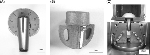
Six cemented Affinis stems of titanium base alloy (TiAl6V4) of the size 9, referred to as “standard stems,” and three cementless Affinis stemless shoulder prostheses of TiAl6V4 alloy of the size 1, specified as “stemless,” were used. Whereas the standard stem surface is shot-peened, the stemless surface is titanium plasma-sprayed and coated with calcium phosphate. All heads had a diameter of 43 mm and a head height of 15 mm. Six ceramic heads fabricated from alumina ceramic (Al2O3 Bionit 43/15/2) with a concentric bore taper and three heads made from a cobalt–chromium alloy (CoCr28Mo6 43/15/2) with an eccentric bore taper (offset of 3 mm) were tested (Figure 1). All tested stem tapers had an identical cone design and taper specification.

Before testing, all taper surfaces were scanned pointwise with a Leitz PMM 866 coordinate measuring machine (Hexagon Metrology GmbH) with an LSPX5 probe head. Diameters at five z-levels were measured with 36 scan points and the entity of points mathematically linked via the Gauss method determined the taper angle.
Tactile surface roughness measurements of each taper sample were performed with the measuring device Form Talysurf PGI DIA Testor 7521 (Taylor Hobson Precision). According to DIN EN ISO, 4288:1998 cutoff wavelengths and measuring distances were specified with a 0.8 mm Gaussian filter and 5 × 0.8 mm for the head tapers and a 2.5 mm Gaussian filter on 5 × 2.5 mm for the stem tapers. All samples were measured at three different locations with a radial distance of 45°. The arithmetic average roughness (Ra), the average maximum profile height (Rz), and the core groove depth (Rk DIN EN ISO 13565-2) were determined.
In addition, 3D topography images were obtained with a confocal microscope (μsurf expert; NanoFocus AG). The measuring field of 1.57 × 1.57 mm was acquired with a ×10 magnification objective and a vertical resolution of 20 nm.
2.2 Impaction procedures
For standard stem endoprostheses, the assembly device was placed on a vibration-damping mat of rubber to reduce the vibrations on the underlying force measuring platform. Each stem was tightened into the device ensuring a horizontal orientation of the plane taper surface (Figure 2A). The modular stem cone was placed on the determined position of zero offsets in the medial-lateral direction and tightened to the position by a screw connection with a fixed torque of 12.5 N·m. The humeral head was then placed onto the stem cone without any axial force. For the eccentric CoCr28Mo6 heads, position 12 of zero anterior–posterior offset was chosen. For the investigation, a sensorized (PACEline CLP/62 kN; HBM GmbH) head impactor made of polyoxymethylene was used (Figure 2B). The force measuring platform consisted of a multicomponent dynamometer (type 9255C; Kistler Instrumente AG) with a laboratory charge amplifier (type 5011B) that operated in the measuring field of 0–10,000 N (1000 N/V) with a low-pass filter at 30 kHz. The transformed signals were measured with a sampling rate of 50 kHz by the NI USB-4431 box (National Instruments) and recorded by the software LabView (National Instruments). The surgeon applied typical strokes with a surgical hammer of 500 g with the right arm.
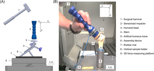
The surgical implantation procedure intends to impact the stemless component with the upper fin surfaces parallel to the resection plane of the humerus.30 Three artificial humerus bones (medium size, left side, No. 1013, Sawbones Corp.) with cancellous inner material (cellular rigid polyurethane foam 12.5 pcf, density 0.28 g/cm2) and a solid cortical shell (solid polyurethane 17 pcf, density 1.64 g/cm2) were prepared using standard surgical tools. After preimpaction, the humeri were positioned and fixed in a vertical sample holder using epoxy resin. The stemless components were preimpacted with the positioner tool until the fins had at least 2 mm of height above the resection plane. The cones were cleaned and dried before the ceramic heads were first mounted by a compressive hand movement. Then, the sensorized hand impactor was applied to impact the prosthesis until the head had an even level with the resection plane.
 =1):
=1):
 (1A)
(1A) (1B)
(1B) ) was calculated using the following equation:
 (2A)
(2A) (2B)
(2B)2.3 Pull-off test
Taper fixation strength was determined in pull-off tests according to ASTM F2009.31 Before testing, the stems joined with heads were shortened manually with a cut-off grinding machine. Therefore, the standard stem was cut to a length of 40 mm, and all fins of the short stems were removed as shown in Figure 3. The shortened components were positioned in a sample holder and then were placed into a servo-hydraulic testing machine (Type HBT 100; Zwick Roell GmbH & Co. KG). A linear axial displacement rate of 0.05 mm/s disassembled the taper junction. The control cube servo controller and Cubus testing software recorded continuously the distance traveled and the force applied over time.
2.4 Evaluation of taper engagement
Taper engagement areas were evaluated with regard to four different radial sectors with 45° offset (shown in Figure 3A). They are referred to as anterior (head position 3), lateral (12), posterior (9), and medial taper area (6).4 Therefore, the components were photographed and inspected using a stereomicroscope.
2.5 Statistical analysis
The descriptive data are mean ± standard deviation. Differences between study groups were compared using the one-way analysis of variance with a Bonferroni post hoc test.32 Level of significance was set at *p < 0.05 for all statistical tests. The statistical analysis was performed using Origin software 2018 (OriginLab Corporation).
3 RESULTS
3.1 Taper geometry and roughness
Before testing, the initial taper angles and roughness were measured. The mean values of the head and stem taper angles are shown in Figure 4A. A significant difference (p = 0.002) was present between the CoCr28Mo6 alloy heads (mean angle of 5.77° ± 0.006°) in comparison to the Al2O3 head tapers (mean angle of 5.786° ± 0.007°). No difference in mean taper angles was observed between standard and stemless tapers for the different stem designs. Both taper types exhibited similar mean taper angles with 5.69° ± 0.023° and 5.7° ± 0.027°, respectively. In comparison to the head taper angle with an angular variation of 0.02°, the stem taper angles had a greater variation of 0.07° (range from the minimal angle of 5.65° to maximum of 5.72°).
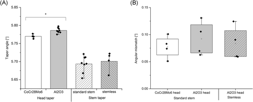
The resulting angular mismatch (known as taper clearance) for the assembled head to stem tapers is presented in Figure 4B. All tested samples exhibited a positive taper clearance in the range from 0.05° to 0.13°, which would result in a deeper taper lock up (proximal direction) between the stem and head taper at axial alignment. Ceramic tapers showed a slightly higher angular mismatch than CoCr28Mo6 humeral head junctions, based on the higher variation of taper angle for the ceramic bore tapers. This difference was not significant between the investigated study groups.
The topography of the new tapers is illustrated by confocal microscopic images and exemplary tactile roughness profiles in Figure 5A–C. Different surface finishes were present on the investigated tapers. CoCr28Mo6 alloy head tapers exhibited periodic machining marks due to a turning process whereas the Al2O3 bore tapers had an aperiodic roughness profile based on a grinding process. TiAl6V4 alloy stem tapers also exhibited an aperiodic surface finish due to a final corundum blasting.
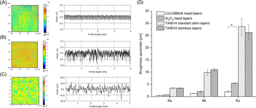
The corresponding roughness parameters Ra, Rk, and Rz are shown in Figure 5D. For the head tapers, the mean Ra values varied between 0.45 and 0.77 µm for CoCr28Mo6 and Al2O3 head tapers. Regarding the roughness height Rz, Al2O3 heads exhibited a doubling of the profile height with 5.49 µm in comparison to CoCr28Mo6 heads with a mean value of 2.03 µm (p = 0.013). This significant difference can also be seen in the exemplary roughness profiles (Figure 5A,B). In comparison to the head tapers, the stem tapers exhibited five times higher mean Ra value of 3.5 µm. This indicates that the head tapers are smoother than the corundum blasted stem tapers. The Rk and Rz values verify the difference between the head and the stem tapers regarding the surface roughness. The mean Rz value for standard and stemless components of 28.6 and 26.3 µm, respectively, exceeded the Rz values of the head tapers by a factor of minimum 5.
3.2 Impact force magnitude and load–time history
In the scope of impaction tests, two different assembly techniques were performed. First, standard stems were assembled using an assembly device provided by the manufacturer. Then concentric Al2O3 humeral heads were impacted to the stemless components that were preimpacted into the artificial humeral bone.
In Figure 6, the load–time curves and magnitudes of the impaction forces measured in the sensorized impactor are illustrated. The joining process of all standard stem prostheses was performed with two strokes and of the stemless prostheses with six to eight strokes by an experienced surgeon.
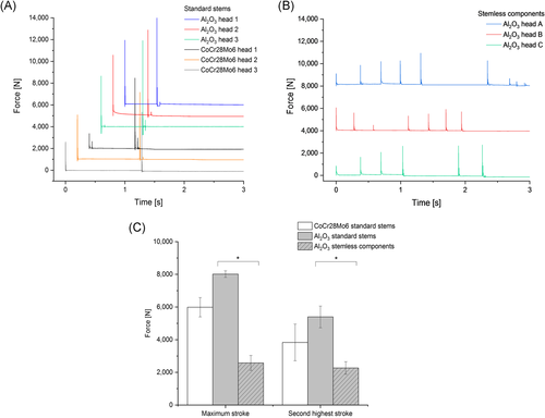
Regarding the standard stems, the first stroke had always a lower force magnitude in comparison to the second one. The force magnitudes of the first strokes varied in the range from 2600 to 5945 N and did not show a difference between the head types. The mean values of the second stroke (maximum force) were slightly lower for eccentric CoCr28Mo6 with 5987 ± 592 N than for concentric Al2O3 heads with 8017 ± 204 N.
The stemless tapers were impacted with several strokes and their force magnitudes varied between 502 and 2938 N. There was no trend regarding the force magnitude sequence. Therefore, the maximum force occurred either at the first, sixth, or seventh hammer stroke with force magnitudes between 2063 and 2938 N. The maximum forces were significantly lower in the stemless impaction in Sawbones than for the standard stems in a stiff fixture, assembling the same concentric Al2O3 heads (mean force values of 2577–8017 N, respectively, p = 0.004).
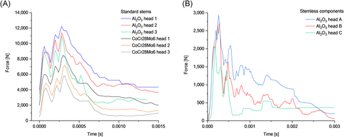
The load–time history and impact duration for the maximum forces are illustrated in Figure 7. The standard stem assembly was characterized by presumably inertial peaks until the maximum force magnitude occurred. All tested stems showed this characteristic load–time relationship that was independent of the head material. The impact duration varied between 0.6 and 1.5 ms with a mean value of 1.25 ms. In contrast, the stemless impactions started with a steep increase in force and a following decrease of the maximum load. The loading duration was about 3 ms.
In addition, the vectors of the maximum resulting force of each hammer stroke were determined and their counterforces are illustrated in Figure 8A,B. The results show a marked difference between the two applied assembly strategies. Small directional deviations were present in the two-stroke impactions on standard stem tapers using the assembly device. The angular deviation to the ideal impaction direction varied between 3.3° and 6.2° for the Al2O3 heads and 4.3°–7.4° for the eccentric CoCr28Mo6 heads. No difference in angular deviation was observed between the first and the second hammer stroke in and between the different head groups (Figure 8C). For standard stems, the impact direction exhibited a pronounced shift in the x-direction with a mean force fraction of 8% than in the y-direction with only 3% on the resulting force (Figure 8D).
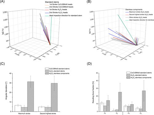
In contrast, the assembly of the stemless tapers into artificial bone revealed larger directional deviations between the multiple strokes with an angular deviation in the range of 18.9°–56.4° to the ideal impaction direction. This directional variance was present in different stroke orders independent of the resulting force magnitude (Figure 8C). The directional shift in y-direction was greater than in x-direction with a mean share of 26% and 12%, respectively (Figure 8D).
3.3 Pull-off forces
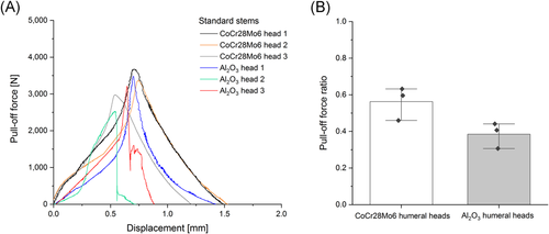
Afterward, the taper junctions were disassembled in pull-off tests to determine the taper strength. Force–displacement curves and force magnitudes of pull-off forces required to disassemble the test tapers are shown in Figure 9. Standard stems exhibit differences in force slope and maximal pull-off forces. The mean value of the pull-off force for the CoCr28Mo6 heads is about 3338.0 ± 349.4 N and for ceramic heads, about 3001.5 ± 672.5 N. For the first 250 µm of axial displacement, the eccentric CoCr28Mo6 head taper curves lie above the concentric Al2O3 head tapers. This indicates that the eccentric heads with TiAl6V4 stem taper require higher forces for similar micrometer displacement. With increasing axial displacement, the curves overlap and result in different maximal pull-off forces.
The ratio of the determined pull-off force against the maximal assembly force reveals that the eccentric CoCr28Mo6 head tapers exhibited a higher ratio than the concentric Al2O3 heads with mean values of 0.56 and 0.37, respectively (Figure 9B). Consequently, the same assembly force magnitudes require higher pull-off forces for the CoCr28Mo6/TiAl6V4 pairing than for the Al2O3/TiAl6V4 taper junctions. The stemless tapers could not be tested since the assembled samples were disrupted already during the cutting process of the fins.
3.4 Taper engagement area
Taper engagement areas were determined macroscopically on all head and stem tapers after disassembly and are shown in Figure 10 and Supporting Information Figure A. Exemplary photographs display a pronounced tilting of the CoCr28Mo6 humeral head in the distal direction to the taper axis. Corresponding local residues of the corundum blasted stem taper surface are evident in the CoCr28Mo6 head bore taper. Regarding the taper engagement area, concentric Al2O3 heads exhibit a smaller macroscopically deformed area in comparison to the eccentric CoCr28Mo6 heads (Figure 10A,B). The taper surfaces of the stemless components reveal no macroscopic clamping marks. However, an asymmetric distal taper engagement was observed in the Al2O3 bore tapers with few metallic residues in opposing areas that indicate a tilted assembly as demonstrated by the photographs in Figure 10B,C and Supporting Information Figure A.

4 DISCUSSION
The aim of this study is to determine the effects of two common assembly techniques of anatomical shoulder endoprosthesis and to identify critical factors influencing taper strength. In particular, taper geometry and topography were characterized and force magnitude, impact direction, and taper engagement were determined.
Since the engagement mechanics between the aligned tapers affect the contact behavior, taper geometry and roughness were measured before testing. The head tapers exhibited a larger taper angle in comparison to the TiAl6V4 stem tapers. Similar taper angles have been described for contemporary hip tapers.33, 34 The resulting positive taper clearance of 0.05°–0.13° indicates that by axial alignment, a deeper (proximal) taper lock is envisaged. This is in line with the majority of hip tapers offered by different manufacturers that exhibit circumferential machining marks and an angular mismatch that leads to a proximal contact situation.34 The very rough corundum blasted stem taper topography contributed to increased variations in the taper clearance in comparison to other taper designs (Figure 4).34 On the basis of previous studies, the wide variation of taper clearance in the tested cohort should be considered critically since it plays a main role in taper strength and thereby influences the occurrence of micromotion.19, 20, 35 In addition, increased angular mismatch have been described to promote component canting, and tilted taper fit was shown to generate high local stress concentrations for hip taper junctions.21
Different impaction strategies of the surgeon were observed for the tested assembly techniques. On the basis of surgical practice, standard stems were impacted with two strokes while placed in the assembly device in comparison with multiple strokes for the stemless tapers placed in the artificial bone. The magnitude of the applied forces varied between the different strokes. A progressive increase in force magnitude can be attributed to the taper's setting behavior that increases the reaction forces of subsequent strikes. Standard stems were impacted with significantly higher peak forces compared to stemless components. This difference may be attributed to variances in stiffness and damping behavior of the rigid assembly device in contrast to the brittle artificial bone. Furthermore, the surgeon limits consciously the impact forces to prevent any fracture damage to the bone. The large variability of the surgeon's impaction forces for similar implants and the same assembly procedure is in accordance with other impaction studies on modular hip implants.26, 36, 37 To prevent micromotion and head loosening, forces of at least 4 kN are recommended for an adequate engagement length and sufficient taper strength of hip taper junctions.29, 38 In the case of the stemless shoulder impaction into the artificial bone, this requirement was not met. Furthermore, variances in mechanical properties between the tested artificial bone and human bone as well as in intraoperative patient position and incisional joint access influence the applied impact force and need to be further evaluated to make binding assembly force recommendations.
The resulting taper strength for standard stems varied between eccentric CoCr28Mo6 and concentric Al2O3 heads with a mean ratio of 0.56 and 0.37, respectively. Rehmer et al.38 and Pennock et al.39 described that the taper strength was roughly equivalent to the magnitude of the strongest impaction. This finding was confirmed in the results using shoulder implants. Other studies have shown a linear correlation of increasing taper strength with assembly force, as well as the pull-off force to be around 45%–50% of the maximum impaction force.29, 37, 38, 40 These observations are again corroborated by the present results (Figure 9B). Studies showed that different material combinations exhibit similar turn-off forces but variances in turn-off moments. Due to the different elastic modulus, the highest turn-off moments were detected for Ti–Cr tapers followed by Ti–Ceramic taper combinations.20, 38 Since the tested femoral head groups did not only vary in material but also in eccentricity, taper angle, and profile height, these additional factors contribute to the observed difference in taper strength.
Impaction duration influences the setting behavior of the aligned components based on material relaxation. A previous finite element study assumed a linear loading history with an impaction duration of 2 s.29 Nevertheless, the present results demonstrate that the time period of the dynamic assembly process is very short (<3 ms) and differs depending on the assembly procedure. Since the same impactor was used for both assembly procedures, the rigid assembly device generated a shorter impact duration, whereas the ductile artificial sponge bone allowed the force impulse to act longer (Figure 7). Krull et al.41 demonstrate that the force–time characteristic of the applied impulse achieves different taper fixation and suggests maximizing impactor stiffness. On the basis of her work and the present findings, the use of an external assembly device is recommended to apply ideal impaction energy without damaging the patient's bone tissue. However, other intraoperative factors (e.g., an extension of the operating time, contamination risk) that can affect this decision must, therefore, be weighed. For direct bone impaction, the influence of bone stiffness on taper strength has to be investigated in future studies.
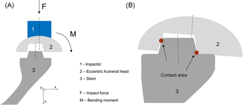
In addition, this study emphasizes the importance of an ideal axial impaction direction. Simulating intraoperative assembly conditions, the resulting force vector varied greatly from the ideal impact direction. Especially for stemless alignment, the angular deviation from ideal impact direction increased with each additional stroke (Supporting Information Figure B). The resulting force vector is influenced by additional factors, including the assembly setup, contact behavior between the tapers and implant-interfaces. However, the results highlight that the surgeon cannot guarantee an ideal axial effective force when using these assembly strategies. Frisch et al.23, 24 investigated the consequence of an off-axis impaction and found a significant deterioration of taper stability that might promote premature fretting motion. Furthermore, all tested taper junctions revealed an asymmetric taper engagement. The reasons for taper tilting are the present angular mismatch in combination with the variating effective force vectors. For the eccentric CoCr28Mo6 humeral heads, the pronounced lateral tilting was caused by the bending moment that occurred due to the lever arm between the stem axis and the head center point (Figure 11).
Tilted taper junctions are known to form crevices leading to a decreased contact area that enhances the risk of fretting and crevice corrosion.42, 43 Interfacial slip and micromotion due to cyclic implant loading continuously destroy the protective oxide layer of the passive metal alloys causing the release of wear particles and metal ions.12, 44 The formed crevice causes local oxygen depletion that accelerates the corrosion processes.45, 46 In this regard, the tested stem tapers were corundum blasted causing the incorporation of abrasive Al2O3 particles in the taper junctions.
There are some limitations to this study. The tested cohort comprises only two anatomical shoulder endoprosthesis types of one manufacturer and was limited in sample numbers. Consequently, the study results are restricted to the tested head geometry, materials, and stem types. Since the common assembly techniques were investigated, some of the variables, such as head material (ceramic, CoCr28Mo6 alloy) to eccentricity as well as implant design (stemmed, stemless) to assembly strategy, could not be isolated. A precise focus on isolated variables is planned in a future study. In addition, the artificial bone does not ideally represent the mechanical properties of human bone. Thus, future studies should investigate typical force magnitudes impacting different implants in human cadaver bone. Furthermore, the impaction tests were performed by one shoulder surgeon and reflect his surgical experiences disregarding the subject variability. The assembled stemless tapers could not be tested regarding their taper strength since they disassembled prematurely during cutting preparation. Although there was no macroscopic evidence of a premature disruption of the taper lock for the stemmed tapers after stem shortening, an impact of the cutting process cannot be excluded. Further investigations are required to evaluate the influence of the cut-off grinding process. To derive the origin of taper tilting, in situ displacement measurements are suggested. This direct measurement would allow differentiating between an asymmetric seating during the component placement or a head canting during impaction. Future studies should consider direct displacement detection.
Nevertheless, this comprehensive study provides for the first time realistic impaction loads for ASA and reveals marked differences in assembly strategy. Stemless components that were directly impacted into artificial bone exhibited a significantly decreased peak load, leading to a deteriorated taper strength. In addition, taper tilting occurred independently of the applied assembly technique. Head eccentricity was identified as a critical promoting factor in taper tilting. On the basis of the present findings, the use of an external assembly device for stemmed shoulder implants is highly recommended to guarantee an axial impaction with a predefined impulse. A sensorized impactor is suggested for better intraoperative monitoring. For stemless shoulder endoprostheses, the in vivo application of a preassembled implant might be accompanied by resultant disadvantages (e.g., poor visibility during mounting).
5 CONCLUSION
The assembly technique critically influences the impact load and consequently taper strength. We identified that the impact direction and head eccentricity are potential risk factors for taper malalignment.
ACKNOWLEDGMENTS
This study was in part conducted within the context of the International Graduate School MEMoRIAL at Otto von Guericke University, kindly supported by the European Structural and Investment Funds under the program "Sachsen-Anhalt WISSENSCHAFT Internationalisierung“ (Project No. ZS/2016/08/80646). The authors would like to thank Anja Schröder, Carolin Schneider, Mandy Könecke, Gabriele Dietze, and Michael Reppin (Otto von Guericke University Magdeburg) for their excellent technical assistance and valuable support. They would also like to thank Professor Jürgen Häberle and Markus Müller from the University of Applied Sciences Magdeburg for the use of their servo-hydraulic testing machine.
CONFLICT OF INTERESTS
Christoph H. Lohmann is a paid consultant for the following companies Waldemar Link GmbH & Co. KG, Mathys Medical GmbH, and ImplanTec GmbH and has royalties from ImplanTec GmbH. Frank Dallmann is an employee at Mathys Ltd. Other authors declare that there are no conflict of interests.
AUTHOR CONTRIBUTIONS
Maria Herbster performed investigations, interpreted data, and drafted the manuscript. Alexander Berth performed the impaction tests and helped with the discussion and interpretation of data. Nicole Märtens helped with the study design and prepared the artificial bones. Marcel Robra developed the test setup, designed and manufactured the sensitized impactor. Florian Welzel provided the sensor and three-dimensional force measuring platform and supported with data interpretation. Frank Dallmann provided the samples and supported with technical data. Christoph H. Lohmann supervised the interpretation of the data and helped writing the manuscript. Thorsten Halle supervised the technical data and drafted the manuscript. Jessica Bertrand designed the study, helped writing the manuscript and to interpret the data. Joachim Döring helped with discussion and interpretation of data and supervised the project. We declare that all authors have read and approved the final submitted manuscript.


