Evaluation of optical 3D scanning system for radiotherapy use
Abstract
Introduction
Optical three-dimensional scanning devices can produce geometrically accurate, high-resolution models of patients suitable for clinical use. This article describes the use of a metrology-grade structured light scanner for the design and production of radiotherapy medical devices and synthetic water-equivalent computer tomography images.
Methods
Following commissioning of the device by scanning objects of known properties, 173 scans were performed on 26 volunteers, with observations of subjects and operators collected.
Results
The fit of devices produced using these scans was assessed, and a workflow for the design of complex devices using a treatment planning system was identified.
Conclusions
Recommendations are provided on the use of the device within a radiation oncology department.
Introduction
Images of patient anatomy are required in radiation oncology for the development of treatment plans, but with the increasing popularity of 3D printing, can also be utilised to produce patient-matched devices, such as bolus, positioning equipment, applicators and shielding. Where medical images are used for device design, they must be geometrically accurate and of high resolution, as a poorly fitted device can cause discrepancies in dose delivery.
Optical 3D scanning is a safe, cost-effective, easy-to-use solution to acquire topographical 3D surface data. In addition to the use of optical surface reconstruction methods for the production of treatment devices such as bolus, moulds and shields,1-11 optical scanning can also be used for patient position verification,12 as well as to overcome limited field of view in simulation imaging.13 Use of 3D optical scanning can reduce the need for radiographic imaging and thereby reduce radiation exposure, facilitate the production of treatment devices prior to CT simulation and is particularly suited to treatment of superficial disease, where the treatment volume is defined on the patient surface.7, 11
The technologies used for 3D scanning vary in cost, complexity and precision. The use of inexpensive smartphones has been described by LeCompte et al.5 and Kang et al.7 Douglass and Santos,4 Maxwell et al.8 and Bridger et al.10 have described the use of consumer-grade camera-based photogrammetry for brachytherapy surface mould and bolus design. Yoshida et al.9 and Skinner et al.11 have described the use of consumer-grade 3D camera systems like the Microsoft Kinect and Intel RealSense for device production. While these solutions are cost-effective, they are often not metrology grade (i.e. providing precise measurement of dimensions), requiring concurrent imaging of reference items of known dimensions and producing less accurate reconstructions than commercial surface scanning systems which may manifest in the form of air gaps between patient surfaces and 3D-printed devices.8
Purpose-built optical surface scanning systems, such as stereo depth scanners13 and structured light scanners,1, 2, 6, 8 are able to produce precise and accurate models of anatomy, suitable for patient-matched 3D-printed devices. Combined with computer-aided design (CAD) software, simple devices, such as uniform thickness bolus or shields14 or nose blocks, can be easily created. The design of complex devices (such as non-uniform compensators) can require the use of a treatment-planning system including a dose calculation engine, which can be achieved through the creation of pseudo-CT dataset11, 15 or where the treatment planning system supports the STL format (e.g. RayStation).
This study aims to provide advice to radiotherapy centres considering the possible introduction of 3D optical scanners into the clinical workflow, by evaluating the practical use of a metrology-grade scanner for two radiotherapy applications: the design and production of simple devices and the synthesis of pseudo-CT datasets for more complex applications.
Methods
Scanner commissioning
The Artec Leo scanner (Artec 3D, Luxembourg) was selected for use due to metrology-grading, the ability to use without requiring a connection to a personal computer, the integrated screen that provides feedback to the operator and other advantages common to high-end scanners identified by Dipasquale et al.2 such as dynamic referencing and the ability to pause and continue scans.
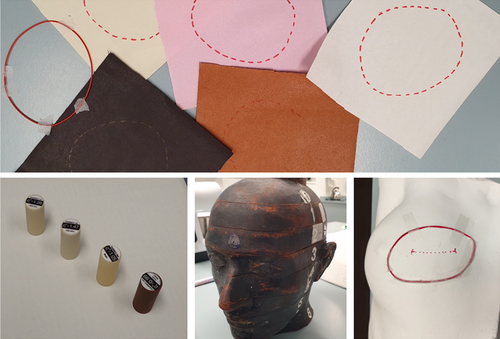
The Artec Leo was commissioned by scanning objects of known dimensions and different colours, specifically white and brown interchangeable rods of the Gammex Model 467 tissue characterisation phantom (Sun Nuclear, Melbourne, USA), a brown head of a RANDO phantom (Radiology Support Devices, Long Beach, USA) and a white plaster positive of a breast with a marked treatment area. The RANDO phantom has previously been used for commissioning of scanners and photogrammetry systems for radiotherapy1, 2, 10 and in some cases has required the application of a powder spray for improved detection, due to the dark tone. Scans were also performed of five leather swatches approximating different skin tones, with both red marker ink and wire markings, on a curved surface. Contrast was assessed by qualitative inspection of reconstructed images and quantitative assessment of pixel value variation. The test objects are shown in Figure 1.
The geometric accuracy of the scans was characterised by computation of Hausdorff distances between STLs produced from 3D scans using Artec Studio (v15, Artec 3D, Luxembourg) and CT images of the test objects, acquired using a Siemens Somatom (Siemens Healthcare, Erlangen, Germany) system with a 120-kVp beam, a reduced field-of-view encompassing only the objects and a 0.5-mm slice thickness. The STL file format is an industry standard for modelling surfaces of 3D objects and is widely supported by design and modelling software. The Hausdorff distance is a geometric measurement of the difference between the nearest corresponding surface points on two registered volumes. These distances were measured using the MeshLab software (Istituto di Scienza e Tecnologie dell'Informazione, Pisa, Italy), as described by Sasaki et al.6
Volunteer scanning
The Artec Leo system was subsequently used to scan surface anatomy of 26 healthy volunteers. The participants were comprised of radiation therapy and medical physics staff affiliated with the department where the study was being conducted. Participants agreed to be available for a scanning session lasting up to 50 min, to be scanned in a ‘radiotherapy treatment position’, to wear form-fitted clothing (to reduce non-anatomical topography in reconstructions) and to be available for fitting of a 3D-printed bolus produced using scanning data.
Prior to imaging, a questionnaire was provided to volunteers to record their self-described sex, height, weight, skin tone and hair colour (using a scale of 1 for very dark to 5 for very pale). Following imaging, a questionnaire was provided to volunteers to record whether the light from the scanner bothered them, whether they were comfortable with the scanning process, and whether they felt the imaging time was too long to be endured by patients. Volunteers were also given an opportunity to provide an open-ended response regarding their experience. These responses were inductively coded using identified recurring themes.
The volunteer cohort included 18 women and 8 men, with an average height of 171 ± 8 cm (1σ standard deviation), average weight of 72 ± 11 kg (1σ) and a broad range of skin tones (dark to very pale) and hair colours (very dark to very light).
For all participants, a scan of the face, head and neck was performed, in a sitting, supine or standing position. Other scans included, in order of frequency, whole body while lying supine, whole body while standing in a relaxed position, shoulder and arm while lying in a recumbent total body irradiation treatment position, arm and hand floating or placed on a surface, whole body while lying prone and whole body while standing in a Stanford pose (used for total skin electron therapy). A small number of scans were also performed with wax bolus, 3D-printed bolus, gel sheet bolus, wire marking and a lead cut-out placed on volunteers. A total of 173 scans were performed.
For two volunteers, the Hausdorff distances between scans taken in sitting and supine positions were calculated, to quantify the potential anatomical variation resulting from differences in positioning of the subject. These calculations were completed using the MeshLab software, as described by Sasaki et al.6
The time taken for each scanning session was recorded, as were observations made by the operator of the scanner (either a radiation therapist or medical physicist).
Bolus fabrication and evaluation
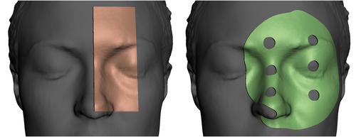
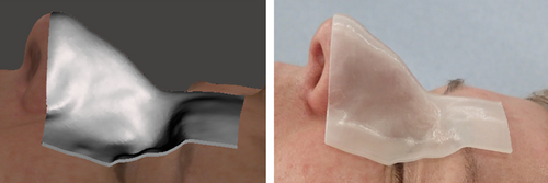
To test the potential clinical application of the surface scans, 2-mm thin 3D-printed boluses were prepared, to cover parts of the glabella, nose, orbits and zygomatic bones, selected due to anatomical variation between individuals, consistency of anatomy over time and ease of reproducible placement of devices. The shape of this bolus was determined by evaluation of two designs for a single participant, as shown in Figure 2: a rectangular strip and a larger circular device including 10-mm-diameter holes; both allowing visual inspection of contact between bolus edge and skin, as described by Dipasquale et al.2
These were designed using Autodesk Meshmixer (version 3.5.474, Autodesk Inc., Mill Valley, California), using the extrude selection functionality for a user-defined region of interest in the scan (selected using the unwrap brush or alternatively by plane cuts), and printed using an Ender 5 printer (Creality3D, Shenzhen, China) using translucent filament (PLA+ Transparent, 3DFillies, Melbourne, Australia) with 100% in-fill. Meshmixer allows efficient design of uniform thickness devices such as bolus or shielding, but the definition of complex features (e.g. non-uniform thicknesses, serration on the edge of a cut-out or brachytherapy catheter channels) may be more easily achieved with other computer-aided design software packages.
The rectangular strip was selected for use with the broader participant cohort, due to simplicity of design and printing (requiring limited-to-no scaffolding) and participant feedback. Test boluses were prepared for participants where facial scans were available with their eyes closed. For each participant, the separation (in millimetres) between the bolus and skin was estimated along each edge by investigators, with any specific regions of disagreement noted. Participants were also invited to comment on how well they believed the bolus fit their anatomy.
Synthetic CT production and use
The STL produced from the scan data using Artec Studio was converted to a stack of DICOM CT images using the 3D Slicer software (version 4.13.0, The Slicer Community),16 by importing the STL as a segmentation, converting the segmentation data to a binary label map volume using an oversampling factor specified to achieve the desired CT pixel and slice spacing, and exporting this data to the DICOM format. This method is similar to that described by Skinner et al.11 This produced a dataset in which the voxels enclosed in the surface geometry were assigned a CT number of 1, and other voxels assigned a CT number of 0. To obtain a water-equivalent phantom the rescale intercept and rescale slope attributes contained in the exported DICOM files were changed to −1000 and 1000 (to convert initial air and tissue values of 0 and 1 to −1000 and 0 HU) respectively. This was achieved using the pydicom library (version 2.1.2).17
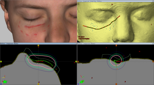
To demonstrate a potential application of such a dataset in departmental systems, a surface brachytherapy mould was designed for a scan of a lower eyelid where a superficial marker was included. The treatment volume and surface mould structures were produced using Meshmixer by selection of the treatment region (indicated by visible ink marking) and a 4-mm extrusion into the body (for the treatment volume) and a 10-mm extrusion away from the body (for an initial iteration of a surface mould). The structures, exported as STL files from Meshmixer, were imported into 3D Slicer along with the generated CT dataset, and exported as RTSTRUCT segmentations (using the SlicerRT extension for 3D Slicer). Catheter and dwell positions and times were defined using the Eclipse treatment planning system (version 13.7, Varian Medical Systems, Palo Alto, USA) and dose calculated on the synthetic CT data.
Results
Scanner commissioning
The scanned dimensions of the Gammex Model 467 tissue characterisation phantom interchangeable rods placed on fabric swatches were 28.1 ± 0.8 mm (1σ) and 69.7 ± 0.4 mm (1σ) for the diameter and length, respectively, compared to 28.5 ± 0.1 mm (1σ) and 70.4 ± 0.1 mm (1σ) as measured with a vernier scale. The largest observed disagreement (0.7 mm) slightly exceeded the combined calculated 1σ standard deviation uncertainty in the measurements (0.5 mm).
Each of the commissioning objects were scanned and successfully reconstructed without the application of the spray powder used by Park et al.1 to improve detection, most commonly for dark, reflective or transparent surfaces.
There were minimal deviations observed between phantom models acquired with 3D scanning and produced from CT scans, with agreement within 0.5 mm (CT slice width) in most regions. The largest differences were observed at superior and inferior ends of scans and at wire markings, where CT artefacts are most common.
The red marker ink could be used for segmentation of reconstructed models featuring light fabric swatches but was difficult to qualitatively resolve for darker tones. Analysis of exported texture image files indicated pixel value variations between marker ink and background swatch colours that exceeded image noise, suggesting that adjustment of contrast or shader settings in 3D modelling software could assist with marker delineation. Physical wires on the phantom surface could be easily resolved in all scans.
Volunteer scanning
The average imaging time for each session, exclusive of questionnaire completion, etc., was 20 ± 11 min (1σ), with an average of 3.3 ± 1.2 min (1σ) per anatomical scan. The feedback provided on the screen of the Artec Leo (a coarse real-time reconstruction) was described as useful and intuitive. Participants who volunteered to test the scanner themselves reported that it was easy to use.
The weight of Artec Leo device (2.6 kg) resulted in some discomfort for the operators of the system, particularly for the extended scanning sessions featured in this study, which lasted up to 50 min. This discomfort would be reduced for the shorter periods of scanning that would occur during clinical use. Operators reported that scanning the participant sitting (or standing) instead of laying supine allowed images to be more easily performed in one scan (minimising risk of potential registration issues that may occur with multiple scans) and avoidance of difficult to reach scanner positions (e.g. panning camera above a supine participant).
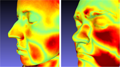
Variations in anatomical dimensions were observed when scanning participants in different positions, seen in Figure 3. The scanning of patients in positions other than their treatment position should only be done with consideration of this.
Twenty out of 26 scanned participants preferred to close their eyes if possible, due to the brightness and strobing effect of the light source used by the optical scanner. The vendors suggest scans can be performed without the light source where there is sufficient ambient lighting. One participant recommended that subjects could look up when closing their eyes, to reduce any discomfort. Six participants were scanned with their eyes open, which complicated the design and fabrication of the bolus, which would protrude into the inner canthus for these volunteers.
Participants scanned in Stanford poses used for total skin electron therapy reported difficulty and discomfort in maintaining that pose for the duration of the scan (which could last 6 minutes). One participant reported that proprioception was more difficult with closed eyes. The wooden frame used clinically by patients to maintain this pose during treatment delivery (approximately 2.3 m in height) and the transparent spoiler screen were not accurately captured, with poor registration of acquired data and visual artefacts. Use of the system for this case would require additional workflow optimisation.
Screenshots of models produced using the scanner including each of the anatomical sites, with and without scanned textures rendered, are shown in Figure 4.
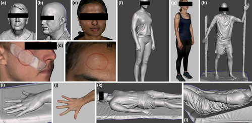
The scanner and reconstruction software performed poorly with head and facial hair (which was reconstructed as a solid surface), large negative spaces (e.g. between a total skin electron therapy spoiler screen and frame and volunteer) and transparent materials (e.g. eyewear and acrylic spoiler screens). Red wax required multiple scanning motions (e.g. sweeping from oblique and acute angles) to be accurately reproduced, presumably due to colour and/or reflectiveness, although this was not required for red felt-tipped pen markings and red wire.
The scanning of features occluded by other anatomy (e.g. behind the ear) required practice or training to perform successfully, as the scanner needed to be rotated to maintain concurrent line-of-sight between the anatomy of interest and both the camera and projector. This limitation resulted in some missing data or artefacts where crevices existed, for example, between supine volunteers and the bed or between fingers that were not splayed.
Minor participant motion for longer scans (e.g. whole body 360° scans) was corrected for by the reconstruction software. There was one instance of motion compromising model reconstruction; however, this motion was sufficiently large to be detected at time of scanning, resulting in a repeated scan, which was successfully reconstructed.
Bolus fabrication and evaluation
For all participants with a bolus prepared (n = 23), visual examination of fit to facial anatomy showed no separation between bolus and skin could be observed for 85% of bolus edges, and that 98% of edges had separations ≤1 mm. No deviation exceeding 2 mm was observed. Regions where agreement were poorest were the alar-facial crease (≤1 mm) and over the globe and eyebrow (≤2 mm). An example fitting can be seen in Figure 5. Twenty participants (87%) reported that the fit felt good or comfortable, with two participants (9%) reporting feeling pressure and one participant (4%) reporting feeling there was a gap between the nose and device.
Synthetic CT production and use
Synthetic CT images and structures were successfully produced by segmentation in Meshmixer and exporting by 3D Slicer (see Fig. 6). These datasets were compatible with departmental image processing and treatment planning software (MIM Maestro and Varian Eclipse).

Whole body datasets were very large when produced at a fine resolution. For example, for one 175-cm-tall model converted to a uniform 0.5-mm voxel resolution, the 3504 slices accounted for 3.87 GB of storage space. Due to the binary pixel value distribution, these datasets were highly compressible, occupying 13.2 MB after lossless zip compression.
Clothing, including fitted exercise wear, was often bunched, ruffled or draped in a way that did not reflect participant anatomy (see Fig. 6 lower left and right). This may introduce uncertainty if scans of clothed patients are used for whole body dose calculations (e.g. for total skin electron therapy) or with deformable image registration algorithms.
As an example of how such synthetic CTs may be used in clinical practice, an example superficial brachytherapy plan was produced using a synthetic CT dataset using the Varian Eclipse treatment planning system (Varian Medical Systems, Palo Alto, California), as shown in Figure 7. The availability of these data in the treatment planning system allowed the optimisation of the mould design (e.g. catheter placement) and could allow optimisation of variable thickness bolus or compensators for treatment of superficial sites. The simple treatment volume structure allowed assessment of dose coverage using dose volume histograms, for a HDR brachytherapy treatment planned using the TG43 formalism.18
Discussion
The scanner was sufficiently intuitive to be used without training and was able to acquire images efficiently without a need for rescanning. Limitations and uncertainties in the geometric accuracy were quantified during commissioning and were acceptable for clinical use, consistent with findings of Dipasquale et al.2 for another high-grade scanning device.
Simple devices produced using 3D scanning were observed to have good skin contact for the participants in this study. For clinical use, a comparison of geometric agreement between designed and printed devices should be undertaken, for example, by scanning of the device and calculation of Hausdorff distances.6 The radiological density of the device (e.g. Hounsfield Units) should also be checked before clinical use, although this can possibly be achieved by in situ use during CT simulation where a 3D scanning workflow has been introduced.
Support for 3D surface scans within treatment planning systems has been recommended in the literature,2 but has not been widely implemented. The synthetic CT data produced using 3D Slicer were able to be imported into clinical systems within the department, including MIM Maestro (MIM Software Inc., Ohio, USA) and the Varian Eclipse treatment planning system. Complex devices requiring optimisation based on dosimetric effects such as variable thickness bolus19 can be designed for synthetic CT data using established virtual device structure workflows without prior knowledge of beam energy and direction that might otherwise be required.2
A major limitation of this method of producing synthetic CT data is the lack of internal density heterogeneities. The absence of bones, lungs, air cavities or even soft tissues with subtly varying densities (such as muscle, brain, liver or adipose) means there can be no accurate calculations of heterogeneity effects on dose and no reliable contouring of anatomical structures for DVH evaluations.
Nevertheless, the synthetic CT data produced in this study allow the calculation of dose where precise models of internal anatomical information may not be necessary for dose estimates, such as superficial brachytherapy using a TG-43 dose calculation model, pre-simulation device geometry optimisation and out-of-field dose approximations. Synthetic CT data could be used to extend or supplement existing images where field-of-view or scanning range was limited (e.g. for paediatric, bariatric or pregnant patients).
While the fit of devices produced in this study was assessed by visual inspection, for clinical use, the fit of manufactured devices could be assessed using medical images acquired with the device in situ (e.g. at CT simulation or cone-beam CT for image guidance), using the air gap method described by Dipasquale et al.2 and Maxwell et al.8
Conclusion
High-grade 3D scanners have been specifically recommended for use in radiotherapy workflows, and the utility of one such scanner, the Artec Leo, in the design of various medical devices has been established in this study. When considering and introducing a new 3D scanner system, it is advisable to commission it by scanning objects of known dimensions and variable colours and of volunteers in radiotherapy treatment positions. Results of this study showed that accurate images could be acquired with this scanner with minimal training due to visual on-device feedback, and the automatic reconstruction processes in Artec Studio produced models with few to no artefacts without user intervention. Potential applications of this work include the use of optical 3D scanners to design and fabricate radiotherapy treatment devices prior to CT simulation, for inclusion in the treatment plan dose calculation. Synthetic CT data produced using the optical 3D scanner could additionally be used for treatment planning in cases where internal density may not be necessary such as superficial brachytherapy where a TG43 approach is used for dose calculation.
Ethics
This study was approved by the Royal Brisbane and Women’s Hospital Human Research Ethics Committee (LNR/2020/QRBW/66064).
Acknowledgements
The authors acknowledge the scan volunteers and staff who provided input and feedback on the applications described by this work, the radiation therapists and medical physicists of the Royal Brisbane & Women’s Hospital Cancer Care Services department. Assistance and feedback were provided by Kate Stewart and Jodi Dawes. Scott Crowe’s contribution to the study was supported by Metro North Hospital and Health Service Herston Biofabrication Institute program funding.
Conflict of interest
The authors declare no conflict of interest.


