Numerical model and effect of site condition on the coupled dynamic characteristics of water storage tank of AP1000 shield building
Abstract
Since the Fukushima nuclear incident in 2011, the focus on nuclear safety has intensified significantly, leading to heightened demands for nuclear power plant modeling to go beyond the mere dynamic analysis of soil–structure interaction (SSI) or fluid–structure interaction (FSI). In current engineering practice, FSI is typically described using simplified forms, such as loads or added mass. However, this approach lacks a comprehensive analytical framework that integrates refined FSI analysis with soil–structure interaction (SSI). This study analyzes the dynamic response of the nuclear island structural system using a fully coupled fluid–structure–soil interaction (FSSI) model. The effectiveness and validity of the model are verified through case comparisons. Simulations were conducted using the parameters of five different types of nuclear power engineering sites for both homogeneous and layered foundations. The results indicated that the hydrodynamic pressure response and acceleration amplification of layered foundations significantly exceeded those of homogeneous foundations, underscoring the importance of considering layered sites in the comprehensive complex modeling of nuclear power projects.
1 INTRODUCTION
After the Fukushima nuclear accident in Japan in 2011, the seismic analysis model for nuclear power based on interaction analysis became increasingly sophisticated. The traditional focus on soil–structure interactions (SSIs) has expanded to include dynamic simulation analyses of complex systems encompassing water tanks, structures, foundations, and the ground. There has been a significant refinement and systematization process for seismic analysis models of nuclear power plants. Third-generation nuclear reactors, represented by the AP1000 from the United States, the Hualong One from China, and the EPR from Europe, place greater emphasis on safety measures. The core of their safety assurance lies in their ability to withstand beyond-design-basis earthquakes. In extreme scenarios, even in the event of core meltdown, the passive self-circulating system of the water tank atop the structure enables 72 h of safe operation without human intervention, ensuring the stability and reliability of the system.1
Previous earthquakes have shown significant differences between the dynamic characteristics of liquid sloshing and those of structures. For instance, the liquid in large swimming pools continues to slosh for several minutes after an earthquake, indicating that water tanks in nuclear power stations may become new sources of post-earthquake seismic activity.2 Furthermore, studies have shown that large liquid storage structures built on soft foundations may exhibit low-frequency elephant-foot effects3, 4 during seismic events. Despite the constraints imposed by the concrete at the top of the safety shell in nuclear power stations, sudden stresses exerted on the concrete during an earthquake can induce tensile stress, thereby increasing the likelihood of instability.
The dynamic analysis models of these systems include the efficiency and accuracy of the dynamic performance of large elevated water tanks, which are excluded in traditional soil-structure dynamic models, under seismic excitation, a finite domain of water exhibits sloshing, which affects the inner walls of the container significantly. The model includes two main components: a pulse mass that is attached to and moves synchronously with the inner walls of the structure and a convective mass connected to the walls by springs.5-7 To characterize the dynamic properties of water more succinctly, the impact on walls is often described by the product of the added mass and acceleration. Early derivations primarily targeted regular rectangular and cylindrical storage structures and developed models from the wave equations of layered water bodies. However, these models have clear applicability issues for annular and bottom-tilted liquid storage structures at the top of nuclear power safety shells.
To analyze an irregular safety water tank in a nuclear power plant, it is necessary to simulate the response of the structure to water. One approach is to simplify a complex water tank into a regular tank for analysis. Examples include the Housner model8, 9 based on unidirectional ground motion in finite domain water and the dynamic water added mass model based on the Westergarrd10 formula in infinite domain water. However, these methods have limitations. For example, the added-mass model provides a method for simple profiles only under the assumption of rigid walls. Additionally, concentrated-added-mass models can only reflect the overall effects and cannot capture the specific responses of the wall sections.
Currently, there is another method for simulating the fluid–structure interaction (FSI) of water tanks that can effectively simulate the effects of FSI in irregular water tanks while ensuring computational accuracy.11-13 By using these methods, it is possible to simulate the impacts of different water levels on a containment vessel14, 15 and further investigate the effects of installing baffles inside the container. For instance, Zhao et al.16 studied the optimization of baffle positions in the passive containment cooling system (PCS) water tank of an AP1000 reactor. In the seismic FSI analysis of complex structural systems, there are primarily two approaches: the first is an early added mass model derived through semi-analytical methods, and the second is a refined finite element model (FEM) developed with the support of modern numerical analysis techniques and based on wave field derivations. Each method has its own strengths and weaknesses in practical application.
To accurately analyze the dynamic response of containment structures under seismic conditions, it is necessary to simulate the ground motion and radiation damping of semi-infinite foundations.17 Sureshkumar et al.18 used the Housner-added mass equivalent model to simulate the FSI effects in finite-domain water. They compared the structural response of cylindrical water tanks under harmonic excitation when considering only FSI and FSI-SSI coupling. Similarly, Larkin and Tam19 used the Housner model to calculate the response of liquid storage tanks under pulse waves when considering FSI-SSI coupling. Yasaghi et al.20 also used the Housner model to study the dynamic response of concrete liquid storage tanks under different foundation parameters. Song et al.21 conducted experiments with a scaled-down model of the AP1000 containment structure and combined numerical simulations using the Housner-added mass equivalent model to simulate FSI effects. They analyzed the stress and strain of the AP1000 containment structure.
Although lumped-parameter-based methods appear more intuitive and straightforward in principle, they are primarily applied in engineering practice. However, this approach struggles to fully capture their complexity. In nuclear power engineering, fluid–structure interaction is particularly challenging due to the significant differences in natural frequencies between the structure and the liquid. The natural frequency of the liquid is typically several seconds or more, and the complexity of the foundation at different sites further intensifies the dynamic response characteristics of the entire system. Although some studies approximate the dynamic behavior of foundations using springs and dampers, this method can introduce certain inaccuracies. To improve the precision of the analysis, this study adopts a complete foundation model and conducts a systematic investigation with refined simulations.13, 22 It delves into the effects of the liquid and overlying soil layers on the dynamic response of the nuclear island structure. This comprehensive simulation approach offers a more accurate understanding of the interactions within the complex system, providing more reliable design guidance and dynamic response predictions for nuclear power engineering.
Integrating the dynamic characteristics simulated through refined numerical simulation methods into interaction analysis has become an important technical approach. This method can be applied to the study of dams, underground structures, and offshore wind turbines under seismic loads. However, in the nuclear power sector, a significant research gap exists in the interaction analysis of coupled dynamic problems based on holistic refined simulations. Therefore, addressing this gap is a necessary engineering requirement.
Based on previous research, the influence of soil foundation stiffness on the behavior of liquid in an upper safety water tank when subjected to seismic excitation remains unclear, particularly regarding the effects on the liquid pulse wave pressure and the relative acceleration experienced at the bottom and top of the structure. In this study, a fluid–structure coupled FEM is used to simulate nuclear power safety water tanks. By using the established FEM and applying appropriate boundary conditions on the free liquid surface to simulate the pulse components, a high-precision SSI simulation program was developed based on the holistic simulation of fluid-structure-foundation interactions. This program investigates the response of nuclear safety-water tanks under seismic action in this complex system by studying the influence of different layered foundation parameters and liquid heights within the tank.
- 1.
The AP1000 FEM was used to investigate the influence of homogeneous foundations with different hardnesses on the hydrodynamic pressure of the AP1000 safety water tank under seismic excitation.
- 2.
To study the distribution pattern of acceleration on the shell of the AP1000 nuclear power plant under two different water level ratios and five homogeneous foundation conditions.
- 3.
To compare the hydrodynamic pressure along the height of the vessel wall of a safety water tank under layered foundations with different hardnesses.
- 4.
To examine the acceleration response of the outer structure of a nuclear power plant under two different water level ratios and four different hardness-layered foundations and compare them with the conditions of homogeneous foundations.
Compared with the traditional Housner model, the fluid-structure-foundation method proposed in this study provides a refined consideration of the SSI, resulting in a more realistic dynamic response of the nuclear safety water tank. Additionally, the effects of layered foundations with different parameters and liquid heights on the structural response of a safe water tank were investigated. The remainder of this paper is structured as follows. Section 2 introduces the computational model used, application of viscoelastic boundaries, and simulation using the coupled acoustic-structural (CAS) method. Section 3 describes the FEM and key inputs. Section 4 presents an analysis of the dynamic characteristics of nuclear water tanks in layered terrain. Finally, the conclusions are summarized in Section 5.
2 MODEL AND THEORY
2.1 FSI considering SSI in nuclear power
When considering the FSI, lumped parameter simulation is widely adopted in engineering practice owing to its computational efficiency and ease of understanding. They play a significant role in engineering applications. Conversely, more sophisticated FSI analysis methods, such as smoothed-particle hydrodynamics (SPH), coupled eulerian lagrangian (CEL), and CAS are commonly used in academic research, which offers significant advantages in reflecting the local dynamic response of the structures. However, despite the ability of the SPH and CEL methods to effectively simulate fluid shapes, they still have certain limitations. For instance, leakage is commonly observed in CEL methods, and there is a trade-off between computational accuracy and cost in SPH methods. Therefore, owing to its computational efficiency and high accuracy, the CAS method can be applied to fluid-structure coupling simulations of nuclear power plant structures. Additionally, boundary element methods23 and scaled boundary FEMs24 have also made progress in FSI analyses.
2.1.1 CAS FEM simulation
Considering the SSI effect, the FSI in a safety water tank induced by dynamic water pressure changes, combined with the correlation between the flow field characteristics and dynamic response of the tank wall structure under seismic action, presents complex characteristics. Therefore, in the seismic response analysis of liquid storage tanks, special consideration should be given to the influence of the dynamic water pressure generated by the water body on the tank wall response.
The CAS method is widely used to simulate the dynamic analysis of liquid storage tanks under the action of dynamic water pressure, and its effectiveness has been experimentally validated.25-27 The advantage of this method is that it uses the control equations of acoustic waves under the action of sound pressure and the fluid motion control equations satisfied by liquid sloshing in the storage tank structure. The use of acoustic elements to simulate the liquid avoids the complexity of directly simulating liquid sloshing, thereby achieving a simple and effective numerical simulation.
Here, is the velocity, with its direction normal to the outer surface of the acoustic medium; both and are along the direction normal to the free surface; is the ratio of pressure to displacement; and is the ratio of pressure to velocity. To simulate the oscillation of a liquid on a free surface under gravity, and were used.
2.1.2 Research framework
Figure 1 illustrates the train of thought and process flowchart for the simulation method of FSI in the water-vessel wall structure of the AP1000 nuclear power plant. Boundary conditions and impedance boundaries must be set. The interaction between the fluid domain and structure can be achieved using tie constraints, ensuring consistency between the dynamic water pressure at the outer nodes of the fluid domain and the inner wall. During modeling, the outer surface of the liquid elements was defined as the slave surface, whereas the inner surface of the liquid storage container was defined as the master surface.
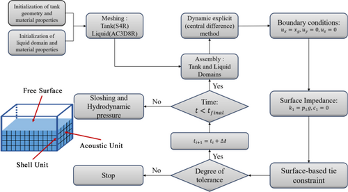
To further refine the details of the FSI simulation method, particularly to enhance computational accuracy and stability, additional clarification on the setting of acoustic impedance is provided. The real part of the acoustic impedance is set to 0, reflecting the transmission capability of sound waves at the liquid-air interface. The imaginary part is set to 0.000102, describing the energy attenuation during wave propagation. This precise configuration ensures that the interaction between the liquid surface and the air is represented more realistically, effectively preventing nonphysical reflections at the free surface and thereby ensuring the accuracy of the dynamic response.
At the liquid–solid interface, a tie constraint is applied to ensure the consistency of relative motion and stress transfer between the liquid and the structure. By setting the outer surface of the liquid as the slave surface and the inner wall of the container as the master surface, the coupling between fluid pressure and structural displacement under seismic loading is accurately captured. This constraint method enhances the feedback effect of the liquid on the dynamic response of the container walls, particularly under high water levels, providing a more realistic representation of the impact of fluid inertial forces on the structure during seismic events.
2.1.3 Validation of dynamic water pressure in CAS method
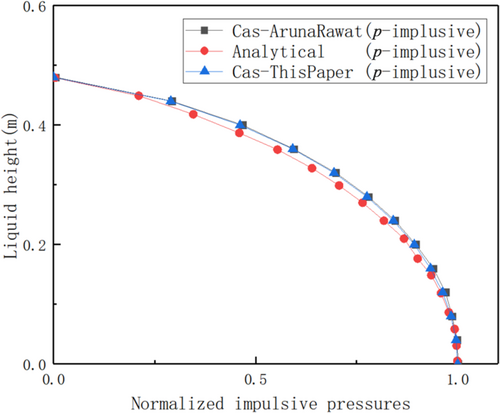
To validate the accuracy of the CAS method used in this study, a simplified computational model based on the AP1000 reactor was established. Two models, the CAS model and an additional mass model, were constructed. The 1940 El Centro earthquake, with a peak acceleration of 0.348 g, was used as the seismic excitation input. A comparison was made between the peak impulse water pressure extracted along the sidewall of the rectangular bottom water tank using the CAS model and the numerical solution obtained using the Housner model,29 as shown in Figure 2. It is evident that the CAS method used in this study yields results consistent with those of Rawat25 in terms of impulse water pressure, further validating the correctness of the modeling approach used in this study.
2.2 Important links of SSI in nuclear power
Owing to the complex structure of the nuclear power plant, safety assessments typically adopt engineering stability strategies. Therefore, this study applied viscoelastic boundaries at the foundation boundary to enhance the stability and accuracy of the simulation results.
Constructing an effective infinite boundary is crucial for studying SSIs. To ensure the accuracy of finite-domain site models in simulating infinite-domain sites, the distance from the finite-element calculation domain boundary of the foundation–soil interaction analysis to the edge of the foundation on the same side should not be less than three times the width of the foundation in the same direction. A viscoelastic artificial boundary30, 31 was used in this study. By applying a parallel spring-damping system with a fixed distant end for each degree of freedom of the artificial boundary, the accuracy of the model was ensured while reducing the size of the computational model. In simple terms, this involves converting the free-field fluctuations at different elevation nodes on the external boundary into equivalent load time histories applied to the viscoelastic artificial boundary nodes.
In this equation, and represent the velocity and displacement free-field responses at the foundation boundary nodes, which serve as the fundamental seismic input data. For homogeneous site conditions, these responses can be obtained analytically based on the traveling wave effect at the boundary. However, for layered site conditions, due to the complexity caused by reflections, refractions, and other effects at material interfaces, they are derived using one-dimensional free-field seismic analysis software. represents the equivalent force vector generated by the free-field response at the foundation boundary nodes. The nodal constraints are defined using the interface motion responses obtained from SHAKE one-dimensional layered site analysis software. A three-dimensional soil column is then employed for step-by-step finite element calculations to solve for the free-field response at the corresponding elevation points.
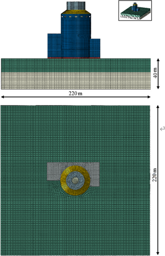
To validate the accuracy and practicality of the infinite-domain radiation damping model used in the simulation, this study selected a numerical model with dimensions of 220 m × 200 m × 40 m,32 and the ground parameters were set to a hard rock foundation with an elastic modulus of 3.78 GPa, density of 2650.81 kg/m3, and Poissons ratio of 0.2. Under Regulatory Guide RG1.60 seismic excitation conditions,33 The foundation consists of 235,320 mesh elements, with a total of 249,711 nodes. The effectiveness of viscoelastic artificial boundaries in simulating seismic wave propagation processes was explored. Specifically, the acceleration response curves of the two monitoring nodes, K1 and K2 in Figure 3, were extracted and compared. The results indicated that the difference between the acceleration curves at nodes K1 and K2 was minimal. This observation confirms that within the studied distance range, the adoption of viscoelastic artificial boundaries effectively simulates the wave propagation characteristics of real soil, thereby providing a reliable simulation method for seismic engineering analyses.

3 REFINED FEM AND KEY INPUTS
Based on the refined FEM of the AP1000 with containment, this study adopted the CAS method to perform a seismic analysis on the safety water tank of the nuclear island.
3.1 Basic computational models and inputs
To investigate the influence of fluid sloshing under different liquid-level conditions in storage tanks, and the effects of different sites on reducing seismic responses when considering the coupling effects of the SSI and FSI, a refined FEM of the AP1000 with site conditions was established.
As shown in Figure 4, the arrangement of the internal components within the reactor building of the AP1000 nuclear power plant is complex, making it difficult to define clear boundary conditions. In his study, the influence of internal equipment on the containment vessel is ignored and a simplified model is used to investigate the stress distribution within an AP1000 building. Specifically, a continuous acoustic element (AC3D8R) with only one degree of freedom subjected to gravity was selected to simulate the liquid inside the storage tank, whereas shell elements (S4R) with three translational and three rotational degrees of freedom were selected to simulate the containment vessel. The material parameters used in the numerical simulations are listed in Table 1.
| Type | Shear wave velocity (m/s) | Density (kg/m3) | Shear modulus (GPa) | Longitudinal wave velocity (m/s) |
|---|---|---|---|---|
| Hard rock | 2438 | 2650.81 | 15.756 | 3981.24 |
| Firm rock | 1067 | 2498.93 | 2.845 | 1742.40 |
| Soft rock | 732 | 2297.40 | 1.231 | 1369.45 |
| Upper-bound soft-to-medium soil | 431 | 1997.19 | 0.371 | 897.20 |
| Soft-to-medium soil | 305 | 1902.71 | 0.177 | 747.10 |
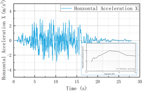
In the selection of seismic design methods, both the American ASCE4-1633 and the Chinese GB50267-2019 codes offer guidance, showing consistency in the choice of seismic design methods. In his study, the response spectrum method was adopted and the prescribed RG1.60 response spectrum was used to generate artificial seismic waves for numerical analysis. The generated artificial seismic wave has a total duration of 28 s with a time step of 0.01 s, and its peak horizontal acceleration reaches 0.3 g as shown in Figure 5.
3.2 Numerical model of layered 3D foundation
To ensure the model's validity and the reliability of the results, several necessary assumptions and simplifications were made in the numerical analysis. However, these assumptions and the model's construction methods introduce certain limitations that must be considered when interpreting the results. Although the CAS method effectively simulates the dynamic response of liquid sloshing, it has limitations in capturing complex nonlinear phenomena, such as liquid surface rupture and turbulence.
In previous studies, scholars often based their research on rigid foundation models (such as soil or rock foundations), neglecting the SSI between the site and upper structure. In this study, the influence of different soil material parameters on the upper structure was investigated considering FSI effects. Two PCS tank water-level conditions were set, as shown in Figure 6, namely, an operational water level of 9.8 m and a low water level of 1.98 m, and refined 3D models were established.
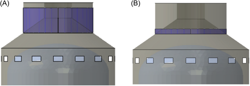
To quantitatively analyze the influence of different foundations on the dynamic response of nuclear power plants, considering the foundation as a homogeneous isotropic material, the foundation types were selected based on the six standard design foundation site requirements for the AP1000. Because the shear wave velocities of the surface soil in the fifth and sixth categories of the standard design foundation sites for AP1000 are the same, the choice is narrowed down to the first to fifth categories of foundations.34 The relevant material parameters are listed in Table 2, with these five sites represented by foundations 1–5.35
| Cases | Homogeneous soil |
|---|---|
| Case 1 | Hard rock |
| Case 2 | Firm rock |
| Case 3 | Soft rock |
| Case 4 | Upper-bound soft-to-medium soil |
| Case 5 | Soft-to-medium soil |
In addition to the basic study of homogeneous foundations, further research on layered foundations is discussed in this study. Four-layered soil conditions were simulated as follows in Table 3: Hard rock to firm rock (Case 1-2), firm rock to soft rock (Case 2-3), soft rock to upper bound soft-to-medium soil (Case 3-4), and soft-to-medium soil to soft-to-medium soil (Case 4-5). As shown in Figure 7, the upper part of the foundation material had a height of 20 m, while the lower part also had a height of 20 m. The following six monitoring points were selected for the model: N1 (13.56, −280, 83.37), N2 (13.56, −280, 71.62), N3 (22.10, −280, 65.64), N4 (22.10, −280, 44.06), N5 (35.66, −280, 28.96), and N6 (35.66, −280, 0). N1 is located at the base of the nuclear island structure and plays a critical role in characterizing the soil's reactive support force on the structure. N2, representing the highest point of the surrounding nuclear island plant buildings, provides a comprehensive reflection of the dynamic response characteristics of the plant.
| Cases | Covering soil | Undersoil |
|---|---|---|
| Case 1–2 | Firm rock | Hard rock |
| Case 2–3 | Soft rock | Firm rock |
| Case 3–4 | Upper-bound soft-to-medium soil | Soft rock |
| Case 4–5 | Soft-to-medium soil | Upper-bound soft-to-medium soil |

N4 and N5 mark transition points in the main nuclear island structure, where maximum stress and strain have frequently been observed in previous seismic response analyses. Notably, N5 is located at the junction between the safety water tank and the main nuclear island structure, making it particularly important for monitoring. N3, positioned between N2 and N4, serves as a transition point, aiding in the analysis of response variations between these two points. N6, as the highest point of the entire nuclear island structure, is highly sensitive to dynamic responses and thus requires special attention.
3.3 Modal analysis
Natural frequency is an important dynamic characteristic that can indicate the stiffness of a structure. The natural period is the reciprocal of the frequency and can be used to calculate the expected response of a structure under seismic action, as well as the expected time-history displacement during a maximum earthquake. The frequencies of each system obtained from the calculations are listed in Table 4.
| AP1000 model without soil (low water) | AP1000 model with soil (low water) | |
|---|---|---|
| Fundamental frequency (Hz) | 2.448 | 2.363 |
| AP1000 model without soil (Operational water) | AP1000 model with soil (Operational water) | |
|---|---|---|
| Fundamental frequency (Hz) | 2.468 | 2.297 |
Table 5 presents the fundamental frequency of the system under five different conditions in a homogeneous foundation. By comparing these frequencies with the governing period of the acceleration spectrum (Figure 5), the overall dynamic characteristics of the system can be evaluated. This indicates that, under hard rock site conditions, the structural response induced by seismic waves constructed based on the given response spectrum is greater than that under soft soil conditions. At the same time, the primary energy band of the input seismic waves does not coincide with the fundamental frequency of the structure-foundation system, reducing the risk of resonance and positively contributing to the overall safety of the system. This result indicates that the model can maintain good dynamic stability under the given seismic wave conditions.
| Case | Fundamental frequency (Hz) |
|---|---|
| Case 1 | 2.298 |
| Case 2 | 1.727 |
| Case 3 | 1.361 |
| Case 4 | 0.630 |
| Case 5 | 0.180 |
4 INFLUENCE OF DIFFERENT SITE CONDITIONS
Under seismic excitation, the sloshing of the liquid in the gravity tank significantly influences the response of the containment structure. There is still a lack of sufficient exploration regarding the coupling effects of SSI and FSI for AP1000 nuclear power plants, particularly in analyzing the influence of different hardness-layered foundations. Numerical simulations were conducted to investigate the effects of different soil and water level conditions on the dynamic response of the response spectrum under excitation. Considering the coupling effects of the SSI and FSI, the impacts of high- and low-water-level conditions and different foundation conditions on the dynamic response are discussed.
4.1 Dynamic response analysis of homogeneous soil layer
4.1.1 Effect of homogeneous foundations on dynamic water pressure
This section mainly discusses the influence of different homogeneous foundations on dynamic water pressure. Figure 8 shows the results obtained by extracting the peak dynamic water pressure from the sidewall of the AP1000 safety tank. When the foundation was composed of hard rock, the peak dynamic water pressure on the tank wall was higher than that when the foundation consisted of medium to soft soil. This indicates that soft soil sites tend to amplify seismic waves, particularly at low frequencies. However, this amplification primarily affected the amplitude of the seismic waves rather than the absolute value of the dynamic pressure. Because of their rigidity and low damping, hard rock sites generally do not amplify seismic waves significantly but can maintain higher energy levels, resulting in higher dynamic water pressures.
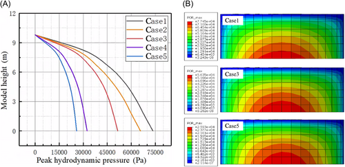
To confirm these findings once again, in the next section the sidewall acceleration of the AP1000 nuclear island structure will be extracted to validate the aforementioned observations.
4.1.2 Acceleration amplification curve
This section focuses on analyzing the impact of different soil conditions on the seismic response of the system, particularly when considering the coupling effects of FSI and SSI. The dynamic response of the AP1000 containment vessel under seismic excitation was calculated based on the homogeneous foundation parameters discussed in Section 2.2: This study covers the effects of different water level conditions and different parameter foundations on the seismic response of the system and provides a detailed analysis of the dynamic characteristics, dynamic water pressures, and relevant experimental phenomena of the model.
By comparing the accelerations of the AP1000 nuclear power plant under different homogeneous soil conditions in Table 6, it was evident that under high-water-level conditions, different foundation parameters significantly affected the relative accelerations at the bottom and top of the structure. In particular, in the case of hard rock conditions, whether at the bottom or top of the structure, the relative accelerations were higher than those under soft soil conditions. Hard rock sites are more likely to transmit high-frequency components, whereas soft soil tends to filter these high frequencies, retaining and amplifying only low-frequency components. High-frequency seismic waves can cause more intense instantaneous dynamic effects, which may be one of the reasons for the higher dynamic water pressures and accelerations observed at hard-rock sites. Conversely, under soft soil conditions, the foundation flexibility is higher, enabling it to absorb more seismic energy and leading to a relatively weakened structural response.
| Cases | N1 (m/s2) | N2 (m/s2) | N3 (m/s2) | N4 (m/s2) | N5 (m/s2) | N6 (m/s2) | |
|---|---|---|---|---|---|---|---|
| Case 1 | high | 3.2599 | 4.52932 | 4.75447 | 8.22543 | 8.58836 | 11.4431 |
| low | 3.25587 | 4.5495 | 5.10433 | 8.34618 | 8.74816 | 10.8222 | |
| Case 2 | high | 3.74508 | 4.20197 | 5.22272 | 8.72021 | 8.62459 | 11.5248 |
| low | 3.72827 | 4.1998 | 5.51019 | 8.79656 | 8.82823 | 11.5918 | |
| Case 3 | high | 3.29697 | 3.63722 | 4.65683 | 7.20603 | 7.3548 | 9.0046 |
| low | 3.25751 | 3.66885 | 4.78486 | 7.12949 | 7.33924 | 8.74568 | |
| Case 4 | high | 2.49783 | 2.79171 | 3.63717 | 4.94258 | 5.19034 | 5.92894 |
| low | 2.49273 | 2.86347 | 3.68649 | 4.93309 | 5.1884 | 5.87945 | |
| Case 5 | high | 2.03609 | 2.03063 | 2.58895 | 3.50467 | 3.6963 | 4.25476 |
| low | 2.02823 | 2.08261 | 2.62285 | 3.51574 | 3.71257 | 4.24395 |
The small differences in acceleration values in Table 6 are due to the fact that, although the presence of water introduces some coupling effects under high and low water level conditions, the structural acceleration response is primarily influenced by soil conditions. The differences between hard rock and soft soil more significantly affect the amplitude and frequency components of the acceleration. In comparison, while changes in water levels alter the mass and dynamic pressure distribution within the water storage tank, they are not sufficient to significantly change the overall acceleration response of the system. This aligns with existing research findings, which indicate that soil conditions play a dominant role in the dynamic response of nuclear power plant structures, while the impact of water level changes is relatively minor.
In addition, the patterns observed in Table 7 are consistent with those in Table 8. First, the model is established based on the actual parameters of the AP1000, in which the rigidity of the tank walls is relatively high and can be regarded as rigid walls. Studies have shown that the hydrodynamic pressure on rigid walls is significantly lower than that on flexible walls.36 Therefore, the FSI has a limited impact on the overall dynamic response of the model. Second, under different site conditions, soil stiffness plays a dominant role in the dynamic response of the structure, particularly in the transmission of high- and low-frequency components. In hard rock sites, the high soil stiffness facilitates the transmission of high-frequency components, leading to similar relative acceleration patterns at different parts of the structure, such as the top and bottom. In contrast, in soft soil sites, the amplification effect of low-frequency components is more pronounced, and similar response patterns are observed between different parts of the structure as well.37 These factors together limit the influence of FSI on the overall dynamic response.
| Cases | N2-N1 (m/s2) | N3-N1 (m/s2) | N4-N1 (m/s2) | N5-N1 (m/s2) | N6-N1 (m/s2) |
|---|---|---|---|---|---|
| Case 1 | 1.269 | 1.495 | 4.966 | 5.328 | 8.183 |
| Case 2 | 0.457 | 1.478 | 4.975 | 4.880 | 7.780 |
| Case 3 | 0.340 | 1.360 | 3.909 | 4.058 | 5.708 |
| Case 4 | 0.294 | 1.139 | 2.445 | 2.693 | 3.431 |
| Case 5 | −0.005 | 0.553 | 1.469 | 1.660 | 2.219 |
| Cases | N2-N1 (m/s2) | N3-N1 (m/s2) | N4-N1 (m/s2) | N5-N1 (m/s2) | N6-N1 (m/s2) |
|---|---|---|---|---|---|
| Case 1 | 1.294 | 1.848 | 5.090 | 5.492 | 7.566 |
| Case 2 | 0.472 | 1.782 | 5.068 | 5.100 | 7.864 |
| Case 3 | 0.411 | 1.527 | 3.872 | 4.082 | 5.488 |
| Case 4 | 0.371 | 1.194 | 2.440 | 2.696 | 3.387 |
| Case 5 | 0.054 | 0.595 | 1.488 | 1.684 | 2.216 |
When designing and assessing nuclear power plant structures, the influence of foundation conditions on seismic response must be thoroughly considered. This not only helps improve the seismic performance of structures but is also a crucial factor in ensuring the safe operation of nuclear power plants during extreme seismic events.
Figure 9 illustrates the impact of different monitoring point heights on the peak acceleration response under full water-level conditions, showing a trend of attenuation in the response peak values as height decreases. In particular, under the layered foundation condition of Case 1, the peak acceleration responses measured at the monitoring points were generally the highest, and these peaks occurred at the highest frequency. To gain a deeper understanding of the influences of different foundation conditions on the peak acceleration responses at the upper part of the structure, a normalization method based on the acceleration measured at the bottom observation point was adopted. The results show that regardless of whether it is under high or low water level conditions, the same pattern is followed. As the foundation parameters transition from hard rock to soft soil, the response at the same monitoring point under hard rock conditions is significantly higher than that under soft soil conditions. This phenomenon reflects the improved energy absorption capability of the softer foundations for seismic waves. Therefore, under seismic excitation, the acceleration response of the structural parts located on softer foundations is relatively small.
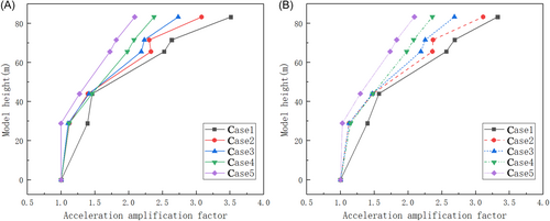
Further analysis of the results in Figure 9 reveals that water level conditions have a significant impact on the seismic response of the structure, particularly under harder soil conditions. At higher water levels, the inertia of the water mass increases, intensifying the dynamic forces acting on the structure during seismic loading. As a result, the higher the water level, the more pronounced the fluid-structure interaction (FSI) effect, leading to a substantial increase in the acceleration response of the AP1000 structure. This finding highlights the necessity of fully accounting for the potential amplification effects of water level variations on seismic responses when designing critical infrastructure, such as nuclear power plants with large water storage tanks.
This finding underscores the importance of considering foundation conditions in the design and seismic assessment of nuclear power plants. Understanding the dynamic characteristics of foundation materials and their impact on structural response is crucial for structures located under different geological conditions. This not only aids in predicting and assessing potential seismic impacts but also guides structural design and improvement measures in specific geological environments, thereby enhancing structural performance and safety when facing earthquakes.
Differences were observed in the peak acceleration responses measured at monitoring points N5 and N6 under seismic excitation. This finding indicates that at these specific locations, the structural response to seismic motion may vary owing to factors such as the local geometric characteristics of the structure, leading to significant differences in the acceleration response.
4.2 Dynamic response analysis of layer soil
This section discusses the impact of different layered foundation conditions on the seismic response of the system, considering the coupled effects of FSI and SSI. Building on the detailed analysis of the homogeneous foundation conditions outlined in Section 2.2, this study further explores the dynamic response patterns of layered foundations and based on this analysis, derives the dynamic response characteristics of the AP1000 containment structure.
4.2.1 Comparison of dynamic water pressure on layer soil foundations
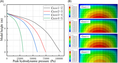
This section discusses the influence of different layer foundations on the dynamic water pressure. Figure 10 shows the results obtained by extracting the peak dynamic water pressure from the sidewall of the AP1000 safety tank. When the foundation is composed of hard and firm rock, the peak dynamic water pressure on the tank wall is higher than that when the foundation consists of upper-bound soft-to-medium soil and medium-to-soft soil. This indicates that soft soil sites tend to amplify seismic waves, particularly at low frequencies. However, this amplification primarily affects the amplitude of the seismic waves rather than the absolute value of the hydrodynamic pressure. Owing to their rigidity and low damping, Case 1-2 generally does not significantly amplify seismic waves but can maintain higher energy levels, resulting in higher hydrodynamic pressures.
4.2.2 Acceleration amplification curve
These analyses underscore the importance of considering the foundation conditions in seismic design, particularly for critical facilities such as nuclear power plants. Consideration of the dynamic characteristics of a foundation is crucial for ensuring the performance and safety of structures during seismic events. It also highlights the need to adopt appropriate designs and reinforcement measures tailored to specific geological conditions for nuclear power plants located in diverse geological settings to meet the ded safety standards (Table 9).
| Cases | N1 (m/s2) | N2 (m/s2) | N3 (m/s2) | N4 (m/s2) | N5 (m/s2) | N6 (m/s2) | |
|---|---|---|---|---|---|---|---|
| Case 1-2 | high | 4.26511 | 5.24221 | 6.36054 | 11.0301 | 10.8899 | 15.3842 |
| low | 3.90722 | 4.689 | 5.64535 | 10.2472 | 10.4652 | 13.871 | |
| Case 2-3 | high | 3.76059 | 3.86042 | 5.30562 | 8.88897 | 8.92735 | 11.3412 |
| low | 3.69308 | 3.95326 | 5.52868 | 8.8185 | 8.98505 | 11.0237 | |
| Case 3-4 | high | 3.27952 | 3.69488 | 5.18879 | 7.69645 | 8.01779 | 9.52132 |
| low | 3.26867 | 3.85907 | 5.29044 | 7.63085 | 7.99105 | 9.33373 | |
| Case 4-5 | high | 2.14033 | 2.5885 | 3.44262 | 5.04681 | 5.33192 | 6.30323 |
| low | 2.12694 | 2.66571 | 3.52077 | 5.06396 | 5.36939 | 6.27488 |
Under seismic loading, a comparative analysis of the acceleration responses of the AP1000 nuclear power plant under several homogeneous soil conditions revealed a significant influence of foundation conditions on the structural response in Tables 10 and 11. From the comparison of the relative accelerations between different structural monitoring points and the bottom of the structure under low water level conditions, Table 8 shows that for hard rock conditions, the relative accelerations at both the bottom and top of the structure are relatively high. This indicates that compared to soft soil conditions, seismic waves dissipate less energy in hard rock foundations.
| Cases | N2-N1 (m/s2) | N3-N1 (m/s2) | N4-N1 (m/s2) | N5-N1 (m/s2) | N6-N1 (m/s2) |
|---|---|---|---|---|---|
| Case 1-2 | 0.9771 | 2.09543 | 6.76499 | 6.62479 | 11.1191 |
| Case 2-3 | 0.09983 | 1.54503 | 5.12838 | 5.16676 | 7.58061 |
| Case 3-4 | 0.41536 | 1.90927 | 4.41693 | 4.73827 | 6.2418 |
| Case 4-5 | 0.44817 | 1.30229 | 2.90648 | 3.19159 | 4.1629 |
| Cases | N2-N1 (m/s2) | N3-N1 (m/s2) | N4-N1 (m/s2) | N5-N1 (m/s2) | N6-N1 (m/s2) |
|---|---|---|---|---|---|
| Case 1-2 | 0.78178 | 1.73813 | 6.33998 | 6.55798 | 9.96378 |
| Case 2-3 | 0.26018 | 1.8356 | 5.12542 | 5.29197 | 7.33062 |
| Case 3-4 | 0.5904 | 2.02177 | 4.36218 | 4.72238 | 6.06506 |
| Case 4-5 | 0.53877 | 1.39383 | 2.93702 | 3.24245 | 4.14794 |
From the analysis in Figure 11, under high water level conditions, there was a trend of attenuation in the peak acceleration response measured as the elevation of the monitoring points decreased. In particular, when the foundation stratification condition is Case 1–2, the peak acceleration responses at different monitoring points were generally the highest, with the corresponding peak frequencies also often being the highest. To gain a deeper understanding of the influences of different foundation conditions on the peak acceleration response of the upper structure, a normalization method using the acceleration response at the bottom monitoring point as a reference was used. The analysis results indicated a consistent pattern under both high and low water level conditions, as the strength of the interlayer foundation parameters decreased from high to low, and the response of hard rock foundations at the same monitoring point was significantly more pronounced than that of soft soil foundations. This phenomenon suggests that softer foundations possess superior seismic wave absorption capabilities, thereby reducing the acceleration response of the upper structure. Hard rock sites typically have higher wave speeds (including shear and compressional wave speeds) compared to soft soil sites. This implies that seismic waves propagate faster through hard rocks with relatively lower energy attenuation. Consequently, higher accelerations were observed at the surfaces of hard-rock sites.
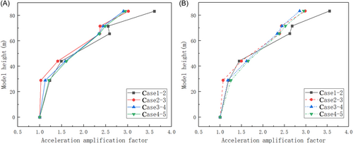
Figure 12 compares the acceleration responses of the AP1000 at homogeneous and layered sites to clarify the differences in the dynamic responses. The acceleration response at the layered sites was significantly greater than that at the homogeneous sites, and the results for the layered sites were closer to those for the softer homogeneous sites. As shown in Figure 12A, the impact of the layered sites on the peak acceleration at the top of AP1000 was twice that of the homogeneous sites. This result indicates that the soil properties of stratified sites play a significant role in amplifying seismic responses. Specifically, the large variations in stiffness between different soil layers lead to complex reflections, refractions, and interference effects as seismic waves propagate through the soil. These interactions result in more pronounced local acceleration amplification. The soft soil layers within the stratified site behave similarly to homogeneous soft sites by attenuating high-frequency components and amplifying low-frequency responses. Consequently, the acceleration response of stratified sites closely resembles that of homogeneous soft sites.
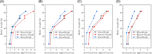
In addition, the acceleration amplification effect of stratified sites is not only prominent at the top but also exhibits a similar trend at other locations within the structure. This can be attributed to local resonance effects caused by differences in the dynamic properties of each soil layer. Notably, at the interfaces between soft and hard soil layers, the significant differences in seismic wave transmission characteristics facilitate localized energy accumulation, resulting in a more pronounced acceleration amplification effect.
FSI is not a dominant factor in the overall dynamic analysis. To further explore the impact of different water level conditions on the nuclear island structure, the results indicate that on stratified hard rock foundations, the effect of high water levels in the tank on the nuclear island structure is more significant. In contrast, on stratified soft soil foundations, the influence of high water levels is relatively minor. The impact of water level variations on the nuclear island structure under different foundation conditions is mainly determined by differences in foundation stiffness, foundation-structure interaction, and water inertia effects. On hard rock foundations, the high stiffness allows more seismic energy to be transmitted to the structure, making the additional mass effect of high water levels more pronounced. Conversely, on soft soil foundations, the energy dissipation and buffering effect of the foundation mitigates this influence.
Future studies could further investigate the relationship between water level variations and seismic wave characteristics to optimize design strategies and enhance the seismic performance of the structure.
5 CONCLUSIONS
- 1.
The feasibility of simulating a complex liquid-structure-foundation model was tested by comparing the hydrodynamic pressure results with those of other authors and validating the reasonableness of the seismic inputs. The differences highlighted in this comparison indicate that the model exhibited good sensitivity.
- 2.
Based on the proposed complex holistic model, detailed analyses were conducted for all five categories of homogeneous nuclear power plant sites, as required by nuclear regulations. The differences between the calculation results for homogeneous and layered sites also reflect the high sensitivity of the model.
- 3.
By comparing the homogeneous and layered site conditions, it is evident that the peak acceleration at the top under the layered conditions is nearly twice as high as that under the homogeneous conditions. This finding indicates that changes in the seismic input wave field owing to layered site conditions significantly affect the dynamic water pressure in the upper safety tanks, highlighting the importance of establishing a comprehensive, refined model.
These analytical findings have significant implications for understanding and improving the seismic safety design of nuclear power plant structures under complex geological conditions, particularly for the design and assessment of nuclear power plants in high-risk earthquake zones.
The simulation platform provides a systematic means for kilometer–level seismic wave field analysis of nuclear structures, considering cluster, geology, and terrain effects.
ACKNOWLEDGMENTS
This research was supported by Grant 52178460 from the National Natural Science Foundation of China, and Grant 52209157 from the Project Supported by National Natural Science Foundation of China. The support is gratefully acknowledged.
CONFLICTS OF INTEREST
The authors declare no conflicts of interest.


