Tantalum Capacitor Separation from Waste Printed Circuit Boards with Molten Salt or Metal
Abstract
Tantalum is the crucial metal of surface-mounted (SMD) tantalum capacitors. Some 50 % of the tantalum mined is consumed in its manufacture, making waste printed circuit boards (WPCBs) an excellent source of secondary tantalum. Yet, its recycling rate is less than 1 %. This paper proposes liberating SMD capacitors from WPCBs by treating them with molten metal or salt. For both processes, the epoxy encapsulation of the capacitors did not disengage from the tantalum core. Furthermore, the molten metal process appears superior to the molten salt one. The tantalum capacitors exit the pyrolysis chamber without salt adhering to them.
1 Introduction
Tantalum, a critical metal 1, is the key raw material of tantalum capacitors used in mobile devices, automobile electronics, medical devices, and other applications due to their small size and better performance compared to different types of capacitors 2. About 50 % of the tantalum mined is used to manufacture tantalum capacitors 3. Because of this, waste printed circuit boards (WPCBs) could be an excellent source of secondary tantalum. Yet, despite tantalum being designated a critical material, its recycling rate is less than 1 % 4.
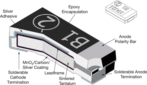
Three different types of tantalum capacitors are used: 1) surface mounted design (SMD), 2) stick-through pearl or film type, and 3) stick-through axial capacitors. In industrial practice, over 90 % of all tantalum capacitors are SMD type 5. Therefore, SMD capacitors were used for this study. SMD capacitors only require minimum space, allowing greater packing densities 2. These capacitors are composed of a tantalum wire, around which a sintered core composed of tantalum, tantalum pentoxide, and manganese oxide is pressed, as shown in Fig. 1. A conductive layer of graphite surrounds the core, with silver as the outside layer. The outer termination of the capacitor is lead, tin, or another solderable material 2. An epoxy resin mould encases the SMD capacitors 2.
Several methods to remove the mould resin surrounding the tantalum core of SMD capacitors are described in the literature. Niu et al. 6 used supercritical water to decompose the mould resin, but the process conditions of 400 °C, 25 MPa, and a residence time of 90 min may result in an expensive process. Reactive, molten salts may also be used. Wajima 7 used molten caustic (NaOH), reasoning that caustic reacts with any halogenated compounds, e.g., HBr generated by the pyrolysis of brominated flame retardants, which may be present in older printed circuit boards (PCBs) 8. A particular difficulty of operating with molten caustic is its corrosiveness. Only nickel, an expensive and challenging to weld material, appears to be suitable to withstand the corrosive nature of molten caustic 9, potentially making a full-scale plant challenging to implement. Matsuoka et al. 10 oxidized tantalum capacitors at 880 °C for 30 min, turning the resin into a powder composed mainly of SiO2. In contrast, the sintered tantalum core remained intact to be separated and recycled by others. But the high operating temperatures required for oxidation appear excessive only to remove the resin. On the other hand, Niu et al. 11 pyrolyzed tantalum capacitors at 400 °C, 50 Pa, and 60 min into gas and pyrolysis oil. The tantalum-containing core remained intact, to be crushed in a follow-on operation to allow the recycling of tantalum. In summary, pyrolysis could be a suitable process to remove the resin surrounding the tantalum core of tantalum capacitors.
A prerequisite for recycling tantalum from WPCBs is that the SMD tantalum capacitors must be separated from the WPCBs 10. But separating the capacitors from the WPSBs is challenging economically as an automated process to remove tantalum capacitors from WPCBs does not exist 12. It is possible to remove tantalum capacitors from WPCBs manually, but this requires significant labor and may, therefore, commercially not be viable 13.
The recycling of metals such as copper and steel from waste printed circuit boards in molten salts was shown by earlier experiments 14. This paper extends those experiments to the recycling of SMD tantalum capacitors. First, it proposes liberating SMD tantalum capacitors from WPCBs by treating them in molten salt or on molten metal. Second, the liberated tantalum capacitors are collected, increasing the tantalum concentration and allowing tantalum recovery. In the following, evidence is provided that the process works as intended.
2 Material and Methods
2.1 Methods
2.1.1 Experiment No. 1 – Liberation of SMD Tantalum Capacitors from WPCBs in Molten Salt
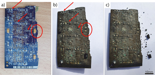
Ten WPCBs populated with large numbers of SMD tantalum capacitors of various sizes (see Figs. 4a and 5a for examples) were, if necessary, marked for identification purposes and photographed. Other electronic components, such as resistors, transistors, and integrated circuits, may also be of SMD type, i.e., mounted directly onto the surface of a PCB. The WPCBs used in this study also contained SMD resistors. However, SMD-type transistors or integrated circuit boards were not present. Instead, if present, those components were of stick-through design (see Fig. 5a for an example).
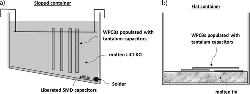
The WPCBs were placed inside a 316L stainless steel sloped container and secured by a steel wire in a vertical position, as shown in Fig. 2a. The container's bottom was sloped by 30 degrees, generating a low point at which the solder and other materials which fall off the WPCBs should collect. The container was filled with eutectic LiCl-KCl salt, which, if molten, resulted in a liquid level of about 10 cm depth, as indicated in Figs. 2a and 3. The LiCl-KCl salt is a heat transfer medium only and is in direct heat contact with the WPCBs ensuring rapid heat transfer. This sloped container was placed inside a reactor.
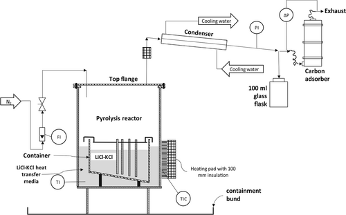
The reactor (Fig. 3) was manufactured from a 6” (125 mm) ANSI schedule 10, 316L stainless steel pipe. A 3-mm thick 316L stainless steel plate was welded onto the pipe as the bottom wall of the reactor. By unbolting the top flange, the reactor could be opened. The pyrolysis vapors were condensed by a water-cooled heat exchanger and collected in a 100-mL glass flask. The formation of an explosive atmosphere within the pyrolysis reactor vapor space and downstream equipment was prevented by initially nitrogen-inerting the equipment and continuously sweeping the pyrolysis reactor with a nitrogen flow of ca 0.1  . The operating pressure was slightly above atmospheric (10–20 mbar), preventing air ingress. The space between the reactor walls and the container was also filled with eutectic LiCl-KCl salt, acting as heat transfer medium between the reactor walls and the inner container.
The reactor was heated by three ceramic electrical heating pads and was insulated with 100 mm glass wool. An Ashcroft temperature gauge (range of 0 to 500 °C, with a 1 % ASME B40.3, Grade A accuracy inserted into a thermowell manufactured from 316L stainless steel) was used to measure, but not to control, the operating temperature. A control system maintained the operating temperature to an estimated ±5 °C (Stork Copperheat 50 KVA Heat Treatment Module, Model no. 16050). The temperature feedback to the heat treatment module control system was provided by a thermocouple between the reactor's outer wall and one of the heating pads (denoted as TIC in Fig. 3). More detailed information on the experimental setup is provided in 14.
The operating temperature was set at 420 °C, as was already done in 14. Such an operating temperature is higher than the resin decomposition temperature of 380 °C 11 and high enough to melt any solders 8. The operating temperature was further increased by 50 °C to ensure the reaction would be completed reasonably fast 14.
Once the operating temperature of 420 °C was reached, it was maintained for 60 min to ensure the pyrolysis reaction was completed. The heat supply was turned off and the chamber was naturally cooled to ambient. Once cooled down, the nitrogen flow was switched off. Finally, the reactor was opened and the container was removed. Hot tap water (70 °C) was used to remove (dissolve) the salt gaining access to the treated WPCBs and the material collected at the low point.
The temperature gauge (TI in Fig. 3) indicates the operating temperature, but it does not measure the temperature of the material within the container. Therefore, this temperature reading needed to be calibrated to the operating temperature inside the container. As the heating was from the outside, a large temperature gradient within the reactor was likely till an equilibrium was reached. Therefore, during the commissioning of the experiment, heat-sensitive paint was used to calibrate the temperature gauge with the actual temperature inside the container 15.
The force required to remove the tantalum capacitors was measured with a handheld mechanical force measurement instrument. The instrument was secured in a holder and individual SMD capacitors were removed from the WPCBs by pressing them against the force transducer till the capacitor was removed. At least ten measurements were made for each case, and the average maximum force was calculated. The instrument was a FA 50 force gauge (Kern + Sohn GmbH, Germany) for measuring push and pull with a peak hold function; measurement range to 50 N, precision 1 %.
2.1.2 Experiment No. 2 – Liberation of SMD Tantalum Capacitors from WPCBs with Molten Metal
The WPCB molten metal experiments are analog to the experiments with molten salt described above, except that the container had a flat bottom and contained molten tin (ca. 1 cm depth). Due to the higher density of tin than salt, the WPCBs would float on the molten tin, as schematically shown in Fig. 2b. Seven WPCBs of various sizes and different components were added to the reactor at any time. About one third of the WPCBs were placed so that the components faced the molten metal, one third was facing the other direction, and one third was placed as a second or third layer. The experiment was repeated, resulting in 14 treated WPCBs. In contrast to the molten salt experiments where the solder and other materials which also disengaged from the WPCBs may collect at the low point, in this experiment, the solder would alloy with the molten metal should it drip off the WPCBs. Moreover, any component that disengages from the WPCBs would float on the molten metal.
2.2 Materials
Renewi, a Belgian waste collecting and recycling company, provided the WPCBs. The salt was a eutectic mixture of technical grade lithium chloride (LiCl) and potassium chloride (KCl) salts (41.8 mol % KCl and 58.2 mol % LiCl (LiCl-KCl)) having the relevant physical properties given in Tab. 1 in its molten state at 450 °C. LiCl-KCl salt was chosen for these experiments as it is stable, nontoxic, and inert at the operating temperatures 16. Additionally, 316L stainless steel is a suitable material of construction for molten LiCl-KCl 17. LiCl was supplied by Leverton Clarke, Basingstoke, UK. KCl was provided by Scientific & Chemical Supplies Ltd, Cork, Ireland. The tin was 99.95 % pure, presented in small lumps, and purchased from Amazon. 316L stainless steel is a suitable material of construction for molten tin 18 and molten LiCl-KCl 9. The nitrogen was certified 99.999 % pure.
|
Compound (at the operating temperature of 400 °C) |
LiCl-KCl (molten) |
|---|---|
|
Density [kg m−3] |
∼1600 |
|
Surface tension [N m−1] |
∼0.13 |
|
Viscosity [Pa s] |
0.00146 |
|
Melting point [°C] |
355 |
|
Vapor pressure [Pa] |
133 at 800 °C |
3 Results and Discussion
The purpose of the molten salt and molten metal WPCB trials was to demonstrate that SMD capacitors can be liberated from WPCBs, separated, and collected for recycling.
3.1 Experimental Results WPCBs in Salt
After salt removal, a visual inspection of the treated WPCBs reveals that solder is no longer present on the WPCBs (Fig. 4). Moreover, the solder collected at the low point of the sloped container (Fig. 2a). Most of the capacitors, however, remained on the WPCBs. Only about 10 % dropped off and collected at the low point. The force needed to remove these remaining capacitors from the WPBs was about 100 times lower than the force required to remove them from the untreated WPCBs (see Tab. 2).
|
SMD capacitor |
Original WPCBs |
Molten tin WPCBs |
Molten salt WPCBs |
|---|---|---|---|
|
Small type |
33–46 |
0.2–0.3 |
0.1–0.2 |
|
Large type |
42–55 |
0.2–0.4 |
0.1–0.2 |
3.2 Experimental Results WPCBs on Molten Metal
In the molten salt process, the WPCBs were vertically and held in place by a wire, allowing molten solder to drip off. But in the molten metal reactor, the WPCBs had to be placed horizontally as the WPCBs cannot sink in the molten tin and on top of each other, as shown in Fig. 2b. Because of that, the solder connecting the SMD capacitors to the WPCBs could only spread out rather than drain off (Fig. 5). Likewise, even the solder of WPCBs facing the molten tin only spread out instead of draining off. Nevertheless, the connections of the SMD capacitors to the WPCBs weakened nearly as substantially as in the molten salt process. As a result, the measured force to remove the capacitors from WPCBs treated by the molten metal process is marginally higher than in the molten salt process (Tab. 2).
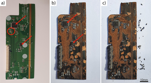
Although molten tin alloys with copper, gold, and other metals 19, no evidence from any PCBs treated shows that PCB metals dissolved in the molten tin. This failure appears to be because the metallic PCB compounds did not come into contact with the molten tin as a layer of carbon or glass fiber prevented contact.
3.3 Discussion
Notably, the force needed to remove the SMD capacitors is low enough that a low-force mechanical wiping action would remove the capacitors from the WPCBs while leaving the other components, such as stick-through integrated circuits, behind on the WPCBs. Therefore, a mechanical separation process can separate and collect the tantalum capacitors from the treated WPCBs.
For both processes – molten salt or metal – the epoxy encapsulation of the tantalum capacitors did not disintegrate into a powder nor disengage from the tantalum-containing core. However, deep cracks in the epoxy encapsulation are visible in Figs. 6a and 6b. This result agrees with the findings of Wajima 7, who also did not observe the collapse of the capacitor casing even at pyrolysis temperatures of 550 °C in molten caustic. This is, however, an advantage as larger particles, i.e., entire capacitors, are easier to recover than smaller particles. Furthermore, the non-collapse of the tantalum-sintered compact makes the separation step of the capacitor from the WPCBs more straightforward, as collapse would make the recovery of the tantalum from the recovered material more difficult due to the decreasing particle sizes. Another significant result is that the tantalum sintered compact can be separated easily from the pyrolyzed carbon resin material – again in agreement with Wajima 7.

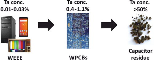
The SMD capacitor recycling process can be described as a tantalum up-concentration process, as shown in Fig. 7. According to Ueberschaar 12, WPCBs from notebooks have the highest tantalum content of about 8 g kg−1 of PCBs. In contrast, WPCBs from smartphones and PC motherboards have tantalum concentrations of just 1.5 g kg−1, which may be too low for commercial recycling of tantalum. Therefore, pre-sorting the WPCBs for high concentrations of SMD capacitors would be necessary for a commercially viable operation.
It is left to future work to design a commercial-scale operation using either molten metal or salt to recycle tantalum capacitors. This includes a possible integration of the process into the existing WPCBs recycling infrastructure and establishing the economics of the process. This paper, however, appears to indicate that a simple mechanical separation process should be able to separate the SMD capacitors from the treated WPCBs.
4 Conclusion
This paper shows that a molten metal or salt pyrolysis process can separate SMD tantalum capacitors from WPCBs. The general recycling procedure for SMD tantalum capacitors would consist of four steps: 1) pre-sorting the WPCBs for high concentrations of SMD capacitors; 2) treating in molten salt or molten metal; 3) separating and collecting the recovered tantalum capacitors for recycling; 4) finally, recycling the tantalum and silver metals.
Acknowledgements
This project is co-funded in Ireland by the Geological Survey Ireland & the Environmental Protection Agency under the ERAMIN2 funding programme supported by the European Commission (Grant No. 2018-ERAMIN2-003). Open access funding provided by IReL.
Abbreviations
-
- FI
-
N2 flow meter
-
- PCB
-
printed circuit board
-
- PI
-
pressure indicator
-
- SMD
-
surface mounted design
-
- TI
-
temperature indicator
-
- TIC
-
temperature indicator control to the heating system
-
- WEEE
-
waste electrical and electronic equipment
-
- WPCB
-
waste printed circuit board


