Electrochemical Recycling of Photovoltaic Modules to Recover Metals and Silicon Wafers
Abstract
An electrochemical-assisted leaching process using boron-doped diamond (BDD) electrodes was developed to recover valuable metals from photovoltaic modules. With BDD electrodes peroxydisulfate is generated from sulfuric acid to oxidatively dissolve copper, tin and silver from solar cell contacts. Since the oxidant is regenerated in the developed process, no additional hazardous and volatile chemicals are required, and the process can be operated solely by electricity. In addition, the dissolved metals can be electrochemically recovered at the cathode of the same cell.
1 Introduction
Since 2000, the installed number of photovoltaic (PV) modules has experienced a steady increase. However, with an estimated lifetime of 25–30 years many of the first installed modules of solar parks are currently reaching their end of life 1. Therefore, the amount of waste will increase sharply in the coming years. According to the Waste Electrical and Electronic Equipment (WEEE) directive of the European Union 2, the panel producers are obliged to dispose of and recycle their modules returned at end of life. The modules contain several valuable materials that can be recovered and reused in the production of new photovoltaics.
The composition of PV modules is displayed in Fig. 1a, the major components are the aluminum frame that stabilizes the module and the solar glass that protects the actual photovoltaic cell. The silicon wafer is encapsulated in an ethylene vinyl acetate (EVA) layer, which is additionally protected from moisture by a polyvinylidene difluoride (PVDF) backfoil. The solar cells are coated with silver stripes for improved conductivity, which are furthermore contacted with solder coated copper busbars that interconnect the single cells within the module.

With regard to the recovery of these materials, several methods for the recycling of waste panels have been described in recent years. The outcome of the respective processes shows a great variety including a simple procedure of crushing the panels 3-6 and reusing the impure remnants as a material feedstock for the industry. More advanced procedures utilize more careful techniques for the separation of the individual layers with organic solvents 7-9 or thermal methods 10-12. Moreover, copper and silver can be recovered by hydrometallurgic processes, mainly with nitric acid 10, 13, 14. If all metal impurities are removed successfully, solar grade Si can be obtained, which has a much higher value compared to metallurgical grade Si and additionally reduces the environmental impact of PV production. However, the widespread use of HNO3 is disadvantageous regarding the generation of large quantities of harmful nitrogen oxides (NOx). Additionally, HNO3 is consumed in the process and has to be added continuously.
Alternatively, oxidizing species can be generated electrochemically. For this task boron-doped diamond (BDD) is an excellent electrode material due to its high overpotential for oxygen evolution. Thus, BDD electrodes have been employed in the generation of strong oxidizers such as hydroxyl radicals 15, persulfate 16, ferrate (VI) 17, 18, periodate 19 or ozone 20 that are mainly put to use in wastewater treatment to degrade organic pollutants 21. Beside this application, BDD electrodes were used in the electrochemically assisted leaching of metals from ashes and slag 22, 23.
 (1)
(1) (2)
(2) (3)
(3) (4)
(4) (5)
(5)In combination with the electrowinning step, we designed a cyclic process for the recovery of metals (Fig. 2a) that is based on electric energy and does not require the continuous addition of chemicals.

2 Materials and Methods
2.1 Materials and Chemicals
All chemicals were obtained by standard suppliers in analytical grade and used without further purification. For leaching experiments with copper and silver, metal foils with a single-side surface area of 1 cm2 and a thickness of 0.2 mm for copper and 0.1 mm for silver have been used. In the case of tin, wires with a diameter of 0.8 mm and a length of 1 cm were used. Plating experiments were conducted with Ag2SO4 (VWR), CuSO4 (Merck) and SnSO4 (Acros Organics). PV modules were obtained from Phaesun (310164) and disassembled by removing the aluminum frame and scraping the backfoil. The EVA lamination foil was removed by swelling and softening it in toluene at 80 °C for several hours. Afterwards busbars can be retrieved from the mass.
2.2 Electrochemical Procedures
Cyclic voltammetry (CV) was performed using a glassy carbon working electrode, a platinum counter electrode and a Hg/HgSO4 reference electrode (Sensortechnik Meinsberg Xylem Analytics).
Electrochemically assisted leaching experiments were conducted in an H-cell (Fig. 2b) with a volume of 100 mL per half-cell that has been described previously 29. As anode, a boron-doped diamond electrode (CONDIAS) with a geometric surface area of 2.5 cm2 was used. A glassy carbon plate (SIGRADUR, HTW Hochtemperatur-Werkstoffe) with a geometric surface area of 8 cm2 was used as cathode. The current was controlled either by a power supply (CTL-3003, QUATPower) or a potentiostat (GAMRY-3000, GAMRY Instruments). The same setup was used for metal plating experiments except for potentiostatic experiments, in which case a Hg/HgSO4 reference electrode (Sensortechnik Meinsberg Xylem Analytics) was placed in the cathode compartment. The half-cells were separated by a cation exchange membrane (F-930rfd, FUMATECH BWT) if not noted otherwise. Alternatively, porous PTFE membranes (Bohlender, BOHLN1690-64) with a pore diameter of 5 µm were used to separate the half-cells as a porous non-selective membrane material.
2.3 Analytical Procedures
The leaching progress was monitored by removing the metal from the solution, washing with deionized water, drying it in an air stream and weighing it. Concentrations of Ag, Cu, Pb and Sn were determined by periodically retrieving aliquots from the solution for analysis by atomic absorption spectroscopy (Varian AAS 240FS) at 328.1 nm for Ag, 324.8 nm for Cu, 235.5 nm for Sn and 217 nm for Pb.
3 Results and Discussion
3.1 Metal Leaching
To evaluate the potential of electrochemically assisted leaching of the relevant metals contained in PV modules the dissolution of pure Ag, Cu and Sn samples were investigated. First, Cu as a moderately noble metal was examined in an H-Cell setup comprising of a three-electrode setup with a membrane as separator. A metal foil with a surface area of 1 cm2 was placed in the anode compartment and its mass weighed periodically during the leaching process with a constant current. As electrolyte solution, several acids were applied to identify an effective leaching medium, but only sulfuric acid (1 M) as well as hydrochloric acid (1 M) gave good leaching results (Fig. S1 and S2 in the Supporting Information, SI). In comparison, the fastest process is accomplished with HCl, however, this goes along with a notable formation and release of chlorine. This is on the one hand an environmental problem and on the other hand a loss of the leaching reagent that will quickly decrease the activity of the solution. Furthermore, the concentration of chloride is further decreased by the previously described formation of perchlorate 30, 31. Therefore, HCl was disregarded and sulfuric acid was chosen as leaching reagent for further investigation.
The dissolution process is influenced mainly by the applied current. A higher current is leading to a faster increase of the peroxydisulfate concentration and thus a faster dissolution (Fig. 3a). Since the initial concentrations of peroxydisulfate are rather low, the dissolution proceeds at much higher rate at the end. The applied current determines the S2O82− concentration and thus the etching rate as shown in Fig. 3a. For comparison, etching times tm were determined at a specific residual mass percentage m, comparable to a half-life period. For a current density of 100 mA cm−2 and 5 M H2SO4 the dissolution of 50 % of a 1 × 1 × 0.2 cm3 copper foil requires a time t50 of 3.1 h, while at 200 mA cm−2 this value is reached in 1.8 h and at 300 mA cm−2 only 1.3 h are necessary. The same trend is observed for the nearly completed dissolution at t20. A further increase in current has a less significant effect as the maximum concentration of S2O82− is limited by decomposition according to Eq. 4 and (5). With higher current, this concentration is reached quicker and thus the dissolution rate increases. For copper, however, a higher concentration of H2SO4 does not improve the dissolution rate as depicted in Fig. 3b.
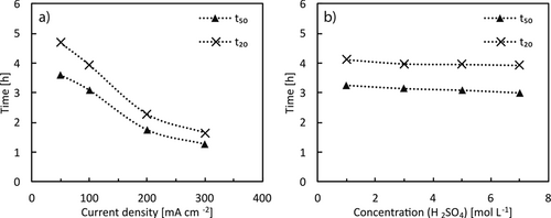
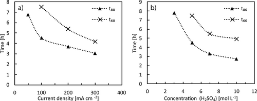
The dissolution of silver is less facile, hence, in 3 M H2SO4 less than 10 % of a 0.1 mm thick silver foil are dissolved within 5 h. Thus, other acids such as hydrochloric acid, perchloric and methanesulfonic acid were tested, though, without success. Using HCl even leads to a mass increase by the formation of a AgCl layer. An increase in the H2SO4 concentration leads to a faster dissolution so that in 7 M H2SO4 40 % of the silver is dissolved within 5.5 h. Higher H2SO4 concentrations did not result in significantly higher dissolution, e.g., in 10 M H2SO4 t60 is 4.9 h. This can be attributed to the limited stability of peroxydisulfate in strongly acidic solution according to Eq. 4 and (5) as discussed above. Thus, maximum accessible concentrations are limited.
Therefore, 5 M H2SO4 has been chosen to investigate the dissolution of Ag by applying different current densities. As expected, the dissolution rate increases with the current (Fig. 4a). As seen for Cu, with increasing current the effect becomes less pronounced. Nevertheless, even at lower current densities an efficient leaching of silver is possible under these conditions.
The dissolution of elemental tin proceeds quickly due to the metal's unnoble nature. As for copper and silver, the rate is dependent on the applied current as shown in Fig. 5a. With increasing current density from 50 mA cm−2 (125 mA) to 300 mA cm−2 (750 mA) the time for a dissolution of 50 % t50 of the material decreases from 2.1 h to 0.9 h in 1 M H2SO4. Again, as described for Cu, the higher the applied current, the lower the relative increase. For t20 the same trend is observed, which confirms that a fast dissolution can be achieved under the investigated conditions.
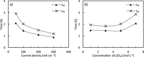
Regarding the acid concentration, an opposite trend is observed compared to silver. For 1 M to 5 M H2SO4 no significant change of the dissolution rate was observed, however, in 7 M H2SO4 the dissolution slows down significantly. This counter-intuitive behavior can be rationalized by the reported low solubility of tin sulfate in concentrated sulfuric acid solution 32, 33. Thus, only medium-concentrated H2SO4 is well-suited for tin leaching from PV modules.
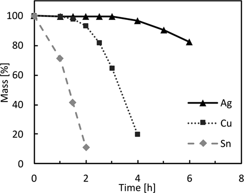
The results from these experiments indicate that 5 M sulfuric acid is best suited to extract Ag, Cu and Sn from spent photovoltaic modules. Subsequently, the three metals were dissolved simultaneously, which resulted in a stepwise process depicted in Fig. 6. It can be seen that Sn is dissolved first, followed by Cu and finally the dissolution process of Ag begins. This behavior is easily rationalized by the degree of nobility of the metals.
3.2 Metal Recovery
The plating of dissolved metals was also investigated to demonstrate the viability of metal recovery. In order to electrochemically isolate the metals, their redox potentials need to be well-separated, thus, cyclic voltammograms (CV) of the relevant metal salts were recorded and are displayed in Fig. 7a.

The peak potentials for the reduction of silver, copper and tin are observed at 0.97, 0.35 and 0.11 V vs. standard hydrogen electrode (SHE), respectively. Therefore, the separation of these metals is feasible. A CV of a solution obtained from dissolving a PV busbar is depicted in Fig. 7b showing the copper reduction wave at about 0.4 V. It is overlayed at higher potentials by a strong reduction wave of peroxydisulfate, which is present in much higher concentration. Thus, the reduction wave of tin is superimposed as well as its oxidation wave, contrary to the copper oxidation, which can be clearly observed at 0.8 V.
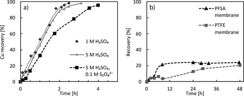
The recovery of the metals was demonstrated by subjecting solutions containing the dissolved metals to a cathodically polarized electrode while monitoring the metal salt concentration. The corresponding concentrations for Cu are displayed in Fig. 8a and show initially a linear increase that approaches 100 % after 2 h. This means a coulombic efficiency of close 100 % is achieved as a charge of 1800 C is transferred, which equals the reduction of 9.3 mM Cu2+. The remaining copper is plated more slowly, as at lower concentration the process becomes limited by mass transport. From 1 M to 5 M H2SO4 no significant difference was observed. However, when S2O82− is present at 0.1 M concentration in the Cu2+ solution the plating was slowed down significantly. This is caused by the reduction of S2O82− in a competing reaction to metal plating, as well as the reoxidation of plated Cu by S2O82−. Thus, very high concentrations of S2O82− should be avoided in the cathode half-cell. If the Cu2+ solution is not placed directly in the cathode compartment, but the ions rather have to migrate through the dividing proton exchange membrane the plating rate is decreased substantially (Fig. 8b). This is a result of the low permeability for metal ions of the utilized proton exchange membranes and the competing migration of protons, which are present at a 10 to 50 times higher concentration. The use of a PTFE membrane with 5 µm pores results in a faster migration of Cu ions that is, nevertheless, much slower compared to the process without membrane.
The recovery of Ag was investigated utilizing lower concentrations of 0.01 M Ag+ as it is less abundant in photovoltaic waste. As displayed in Fig. 9a, the plating takes place quickly as most of the solutions silver content is recovered within 30 min. However, this denotes a coulombic efficiency of only 20 %, which is caused by the employed low concentration. As expected, the presence of S2O82− does not influence the recovery rate since the potential of the Ag/Ag+ couple is far from the reduction potential observed for S2O82−.
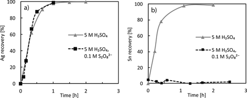
The recovery of tin from a 0.01 M solution in 5 M H2SO4 was also investigated and is comparable to the recovery of Ag. This means the current efficiency is higher as two electrons are required per reduced Sn2+ ion. In the presence of S2O82− no recovery of tin was achieved, even if enough charge was passed to the solution to completely reduce S2O82−. The reason for this might be an oxidation of Sn(II) to Sn(IV), which can precipitate as a dispersed complex form of SnO2. This is confirmed by the absence of a Sn(II)/Sn reduction wave in CV measurements (Fig. S9 in the SI).
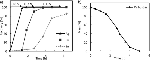
The electrochemical separation of the three metals was demonstrated by applying a potential to a solution 0.1 M in Cu and 0.01 M in both Sn and Ag that was stepwise decreased starting at 0.8 V for the recovery of Ag followed by 0.2 V for Cu and finally 0.0 V vs. SHE for Sn. The concentration profiles for this process are represented in Fig. 10a and show that the plating occurs stepwise and the metals can be separated with the proposed method.
3.3 Metal Extraction and Recovery from PV Waste
The composition of the investigated photovoltaic busbars was determined by fully dissolving them in HNO3. The anticipated main component is copper with 80 wt % that is coated with solder consisting of Sn and Pb in equal amounts of 10 % of the total mass. Such a busbar was dissolved in 5 M H2SO4 while applying a current of 250 mA (100 mA cm−2). The course of the dissolution is displayed in Fig. 10b and a similar trend as for the pure metals is observed. A decrease in the rate is observed at 1.5 h, which occurs when most of the solder coating is dissolved and the dissolution of copper commences, which is slower, as described above. A small amount of about 5 mg of a gray residue remained that was identified as lead. Due to the extremely low solubility of PbSO4 in sulfuric acid no dissolution was achieved. Nevertheless, the powder can be easily separated to be recovered and to avoid contamination of the environment.
Subsequently, the obtained solution was placed in the cathodic compartment of the cell, where a potential was applied and stepwise decreased to separate the metals. Following this procedure, over 99 % of the copper could be recovered. For tin, no recovery was possible due to the presence of S2O82− as described above. The silver coating of PV Si wafers was also leached. From 7.1 g of wafer fragments 112 mg of Ag were leached, which is slightly more than the previously reported Ag content of 0.7–1.4 wt % on wafers 34, 35. The obtained solution had a concentration of 10 mmol L−1 and was subjected to plating conditions with a current of 250 mA (100 mA cm−2). By this, 59 % of the silver content was recovered after 2.5 h of electrolysis.
After 24 h the recovery rate increased to 88 %. The slow recovery is a result of the relatively low silver content compared to the high amount of generated S2O82− present in the solution that causes a competitive leaching reaction as well as competitive H2 evolution. This problem is overcome by leaching larger amounts of PV waste to obtain higher silver concentration to make its recovery more feasible.
4 Outlook and Conclusion
If multiple metals are to be recovered in pure form it is necessary to scrape the first deposited metal from the cathode before continuing with the next as described in this study. Alternatively, separate electrodes for each metal to be deposited at a certain potential could be placed in the cell to consecutively plate the metals one after each other following the electrochemical series on different electrodes, which may be a more viable setup for an application.
This process leaves silicon wafers that can either be further processed to remove the antireflective coating or directly reused for the manufacturing of new wafers. But even damaged wafers can be reused as raw material. An approach in which the wafers are converted into ferrosilicon using iron oxide-rich substances (e.g., red mud) is the subject of current investigations at the TU Bergakademie Freiberg. The aim is to use a silicothermic process to produce Fe-Si alloys that can be used as deoxidizing agents in steel production. For this purpose, the metals investigated in this study must first be removed from the surface of the wafer to prevent contamination of the alloy and thus meet industrial requirements. In summary, boron-doped diamond electrodes can be used to generate peroxydisulfate to etch metal coatings from spend photovoltaic modules. The generation of peroxydisulfate from sulfuric acid as oxidant renders this method a cyclic process, as no reagent is required except for electricity. Silver, copper and tin could be dissolved with this process and silver as well as copper could be electrochemically recovered within the same cell. To further optimize the process, a flow cell setup for faster leaching and recovery is currently under investigation.
Supporting Information
Supporting Information for this article can be found under DOI: https://doi.org/10.1002/cite.202100105.
Acknowledgements
The IGF-project no. 20966 BG/2 was funded by the German Federation of Industrial Research Associations as part of the program for industrial collective research (IGF) by the Federal Ministry of Economic Affairs and Energy. Open access funding enabled and organized by Projekt DEAL.
Symbols used
-
- tm [h]
-
etching time until m % residual mass
-
- m [wt %]
-
residual mass percentage of a sample
Abbreviations
-
- BDD
-
boron-doped diamond
-
- CV
-
cyclic voltammetry
-
- EVA
-
ethylene-vinyl acetate
-
- PV
-
photovoltaic
-
- PVDF
-
polyvinylidene difluoride
-
- SHE
-
standard hydrogen electrode


