CFD Modeling of Reactor Concepts to Avoid Carbon Deposition in Pyrolysis Reactions
Abstract
Methane pyrolysis in an externally heated tubular reactor inevitably ends with clogging of the reactor. Thin molten metal wall films protect the walls from carbon depositions. A falling film reactor and a rotating film reactor are investigated by CFD simulation. The results show the considerable advantages of a rotating film reactor compared to the vertical film reactor. An alternative route for carbon production from methane is the implementation of an exothermic chlorination reaction. The tubular reactor concept involves the inflow of inert gas at the reactant inlet and through porous walls to ensure that the reaction takes place in the center, thus, largely reducing carbon deposits.
1 Introduction
The global hydrogen demand has doubled in the last 30 years from about 35 Mt (1990) to more than 70 Mt (2018). A further increase in demand is expected, as hydrogen has the potential to decarbonise a number of sectors (industry, transport, construction or energy) 1. This is necessary to meet the objectives of the Paris agreement and to prevent climate change in the long term 2. The most common process for hydrogen production is steam methane reforming (SMR), which can meet about half of the global demand for hydrogen. By combining the endothermic reforming reaction with the energy-supplying water-gas shift reaction, stoichiometric amounts of CO2 are produced. Considering the entire process, approx. 10 t CO2 t−1 H2 are produced 3. To lower climate gas emissions, alternative processes need to be developed.
 ()
()If the energy for the reaction is provided by renewable energies, methane pyrolysis can produce CO2-free hydrogen 4.
Various studies on the economic efficiency of methane pyrolysis have shown that small to medium-sized plants in particular are competitive with SMR and water electrolysis. Large plants will only become economically viable if taxes on CO2 emissions are introduced and the carbon can be sold at a sufficient profit. 3, 5
Abánades et al. investigated the thermal decomposition of methane in a tubular reactor. They found out that the pyrolysis reaction inevitably ends with the clogging of the reactor 6. Various concepts have therefore been developed to prevent carbon deposition. Muradov et al. identified a fluidized bed reactor as a promising concept 7. Already in 1961 Jahnig et al. published a patent for an electrically heated moving bed reactor 8. Munera-Parra et al. then showed theoretically that countercurrent operation is an efficient method of heat input 9. The carbon deposits appear at the hottest points in the reactor, so that in the fluidized bed and in the moving bed the carbon deposits are most likely to occur at the walls or electrodes where they would inhibit further energy input and cause clogging of the reactor.
Steinberg and Serban et al. were the first to mention the use of molten metal bubble columns. The separation of the solid carbon by floating on the molten metal offers a decisive advantage 10, 11. Martynov and Gulevich also proposed the use of molten heavy metals such as lead and bismuth as heat carriers for methane pyrolysis 12. Plevan et al. 13 found that most of the methane conversion in bubble column reactor takes place above the molten metal. Geißler et al. investigated bubble column reactors with quartz glass packings to shift the reaction further into the bubble column region 14. The reactor did not clog during operation, but the authors reported carbon deposits on the wall of the bubble column reactor.
Further molten metal concepts were investigated by Schultz and Agar as well as Munera-Parra et al. Bubbles of the reaction gas are passed through a capillary reactor. A wall film in the slug-flow regime should protect the reactor wall from the carbon deposits. The advantage over the bubble column reactors is the control of the residence time. However, wetting problems between capillary and molten metal led to carbon deposits, which finally caused clogging of the reactor. 15, 16
 ()
() ()
()The aim of this work is to evaluate new reactor concepts with regard to their suitability for preventing carbon deposits. For this purpose, three different concepts were developed and examined by means of computational fluid dynamics (CFD) simulations. Two liquid metal film reactor concepts proposed by Munera-Parra et al. 16 are compared simulatively. In addition, a porous wall reactor for methane chlorination is to be investigated.
2 Reactor Concepts and Modeling
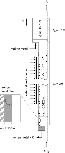
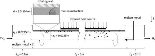
Three promising reactor concepts for the decomposition of methane into hydrogen and carbon have been identified and modeled with the software ANSYS Fluent R19.3. The different reactor concepts are shown in Fig. 1, 2 and 6.
2.1 Falling Film Reactor
In methane pyrolysis, the liquid film serves only as a protective barrier and heat carrier. The concept is shown in Fig. 1. Methane enters the reactor at the bottom, while liquid metal is introduced at the top of the reactor. The countercurrent flow allows using the film to preheat the incoming gas and to cool the reaction product. Another advantageous effect is the separation of the products. Hydrogen escapes at the top of the reactor, while solid carbon is transported via the falling film to the bottom.
For the model of the falling film reactor rotational symmetry is assumed and the inlet and outlet pipes are neglected. The reactor consists of the falling film region with outer radius ra of 0.0125 m and a length LF of 1 m. Above the film region, a box with radius rB of 0.0225 m and a length LB of 0.1 m is located.
A mixture of methane and hydrogen with TG0 = 600 K and a molar ratio of 9:1 is fed to the reactor with a volume flow  of 1 L min−1. Due to low gas volume flow and ambient pressure, the gas flow is simulated laminar and incompressible.
 of 1 L min−1 at a reference temperature of 600 K. This leads to a mass flow
  of 0.12 kg s−1 and a minimum volume flow per wetted unit of perimeter of 0.76 m3m−1h−1, which is between 0.5–1.5 m3m−1h−1 where complete wetting of the wall is achieved 19. The film Reynolds number for the given conditions is Re > 400 so that a turbulent film regime can be expected 20. The Reynolds number is given by
 ()
() , outer radius ra and dynamic viscosity ηL. The thermophysical properties of liquid tin could be calculated by Eqs. 5–8
21-23.
 ()
() ()
() ()
() ()
()The inlet temperature of the molten tin varies between TL0 = 600 K for furnace operation with a furnace temperature Tfur = 1300 K as shown in Fig. 1 and TL0 = 1300 K for heating with the hot film.
 ()
() ()
()with maximum laminar film velocity wmax,lam in cylindrical coordinates given by Eq. 19.
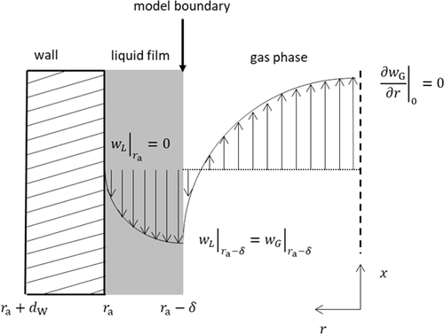
 ()
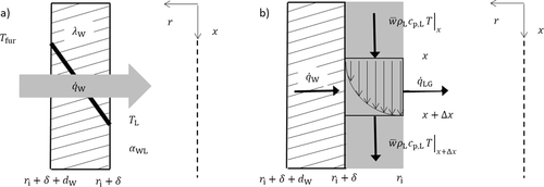
() describes the specific heat loss due to the heating of the cold gas where
  characterizes the specific heat flow through the wall. The equation for
  can be set up according to Fig. 4a and is given by
 ()
()Here λL represents the thermal conductivity, dW the wall thickness and αWL the heat transfer coefficient between wall and liquid.
 ()
() ()
() ()
() ()
() ()
() ()
()During the pyrolysis process, particles of different sizes are formed. These range from primary particles (d = 5 · 10−8 m) to carbon agglomerates (d = 1.28 · 10−6 m) 27. Depending on the residence time in the reactor and the temperature, the primary particles grow and carbon agglomerates will form. The growth process is not represented by the model at first. Initially, the model is only intended to check how efficiently particles of different sizes can be separated by the reactor concepts. Therefore, six different particle sizes are injected from each given particle size range.

2.2 Rotating Film Reactor
The basic concept of the rotating reactor does not differ much from the falling film reactor. The gas and liquid flow are fed into the reactor at different ends as shown in Fig. 2. The film is formed by rotating the tube that connects two static vessels on the left and right ends.
Similar to the falling film reactor, rotational symmetry is assumed. Volume flows of gas and liquid as well as inlet temperatures and composition of the operating media are identical to the falling film reactor model. Since the rotation of the gas flow creates turbulence, the k-ω-SST model is used to describe the gas flow.
The complete wetting of the wall in a rotating film reactor depends on the rotational frequency. The most uniform form of wetting is achieved within annular flow regime. Using a correlation of Chatterjee et al. 28 a rotational frequency rpm of 2000 min−1 has been calculated to guarantee annular flow for the given conditions.
 ()
() ()
() ()
() ()
() ()
()Heat transfer, pyrolysis reaction and particle model are identical to the falling film reactor.
2.3 Porous Wall Reactor
The reactor concept shown in Fig. 6 is based on a patent to produce carbon black and chlorinated hydrocarbons 18. The exothermic energy from the chlorination reaction is used for the pyrolysis reactions of the chlorinated hydrocarbons to generate the solid carbon, thus requiring no heat introduction via the walls. A protective layer is built up near the reactor walls by using the product gas hydrogen chloride. After the area of radial inflow, there is an additional pipe section in which no radial inflow is introduced.

For the concept of this porous wall reactor, the length and width ratios were adjusted to those of the patent and scaled up. The zone where the reaction takes place has a diameter of 100 mm and a length of 500 mm, of which 300 mm correspond to the porous wall.
As gas phase components methane, chlorine, chloromethane, hydrogen chloride and gaseous carbon are considered. The reaction is divided into two reaction steps: the chlorination of methane to methyl chloride and hydrogen chloride as well as the reaction of methyl chloride with chlorine to carbon and hydrogen chloride. The complex mechanism of the chlorination, pyrolysis and carbon generation kinetics were simplified to the two-step reaction, as the generation of carbon out of the gas phase is not part of the simulation. The patent states for inlet volume flow rate ratio of CH4:Cl2:HCl ≈ 0.9:2:6, while 90 % of the HCl gas enters the reactor via the sidewalls, there is no carbon accumulation on the reactor walls 18. This ratio was adjusted to a total volume flow rate of 534 L min−1, with all gases having an inlet temperature of 773 K and atmospheric pressure.
The solid carbon is implemented by injection of particles. To estimate the mass of the carbon, a complete conversion of the methane is assumed, with the mass distributed into different particle sizes ranging from 0.001 to 0.201 mm. The particles are mainly injected into the mixing zone of the reactor in a shape of a hollow cone.
3 Results
First, the results from the falling film reactor are compared with those from the rotating film reactor. The focus is mainly on the comparison of the film velocites, temperature profiles, the reaction rates and the separation of the particles. After that porous wall reactor results are discussed.
3.1 Falling Film and Rotating Film Reactor
In order to be able to compare the results of falling film and rotating film reactor, the operating parameters and the geometries have to be chosen similarly as described in Sect. 2. Tab. 1 compares the characteristic film parameters of the film flow for the falling film and the rotating film reactor.
|
|
Falling film reactor |
Rotating film reactor |
||
|---|---|---|---|---|
|
TL |
600 K |
1300 K |
600 K |
1300 K |
|
Re |
1005 |
2044 |
1005 |
2044 |
|
Rerot |
– |
– |
155 050 |
294 446 |
|
δ |
2.87 · 10−4 |
2.74 · 10−4 |
1.74 · 10−3 |
1.44 · 10−3 |
|
wmax,lam |
1.12 |
1.26 |
0.201 |
0.256 |
|
wmax,turb |
0.995 |
1.01 |
– |
– |
The comparison of film thickness δ and maximum velocities w reveals the biggest difference between the two reactors. Since the film thickness is an order of magnitude greater, the maximum film speed in the rotating film reactor is only a quarter of the speed in the falling film. This leads to less backmixing in the gas phase due to countercurrent flow. Due to the thin film and the high film velocity in the falling film reactor a possible detachment of the film might create non-wetted zones. This might result in carbon deposition, which needs to be avoided. Higher mass flows could solve this problem leading to even higher film speeds.
3.1.1 Heat Input by Furnace
For a maximum furnace temperature of 1300 K, the heat input into the reactor is investigated. For this purpose, the dimensionless axial temperature profiles of the furnace, the wall film and the reactor center and the reaction rates in the film region and the reactor center are shown in Fig. 7.

Regarding the temperature profiles for both reactors, furnace and film temperature are equal. The advantage of the rotating film reactor becomes apparent when looking at the temperature in the center of the reactor. Due to the high velocities in the falling film, the gas velocity in the center of the reactor increases. Therefore, the maximum temperature is located at x* = 0.65 whereas the maximum film temperature can be found at x* = 0.25. In comparison, the slower film and gas velocity in the rotating film reactor are advantageous for the heat input. The maximum temperature in the center of the rotating film reactor is higher than in the falling film reactor. This could also be seen by the higher reaction rate in the reactor center although the difference seems to be very small for this temperature level. Furthermore, the reaction gas cools down much faster in the rotating film reactor. This prevents methane from reacting in the outlet area where no protective film is present.
3.1.2 Heat Input by the Hot Film
Alternatively, the heat can also be carried into the reactor by a previously heated film flow at 1300 K. For this purpose, 80 % of the reactor is insulated starting from the film inlet. The other 20 % are used for film cooling with a wall temperature of 600 K. The dimensionless temperatures and reaction rates for falling and rotating film reactor are shown in Fig. 8.

The center of the falling film reactor is heated more slowly than that of the rotating film reactor. This is again due to the slower gas velocities. Furthermore, in the insulated area (x* > 0.2) almost a constant temperature level is reached. Within the rotating film reactor, the heat can be quickly removed at the end of the film zone, which allows a clear reaction zone to be defined. With regard to the reaction rate, it is noticeable that it is higher at x* = 0.2 in the rotating film reactor than in the falling film reactor. Due to the lower film speed, less product is mixed back, which increases the reactant concentration locally ensuring a higher reaction rate. The demonstrated reaction rates lead to the following conversions: 17 % for the falling film reactor and 19 % for the rotating film reactor. The difference does not seem very large, but it should be noted that in the falling film reactor the gas flow could not be cooled down so that a part of the reaction takes place in the volume above the film zone. With the rotating film reactor, no reaction takes place in this zone.
3.1.3 Particle Separation
As shown in Fig. 5, particles are injected at 153 locations. Each particle is tracked to find the location where it escapes. The mass flow of the particle injection is coupled via Eq. 14 to the reaction rate. Thus, more particles are produced in the zones of high temperatures than in cold zones. The growth of particles from primary particles to carbon agglomerates is not considered. Therefore, six different particle sizes are injected. Based on the different particle sizes, a final assessment can be made as to whether all types of particles can be separated. Fig. 9 shows which particles have left the reactor via each boundary. For the falling film reactor at least a third of the particles leave the reactor via the outlet. These are the particles injected near the reactor center (Fig. 9a).

In the rotating film reactor (Fig. 9b), more than 90 % of the particles of each size leave the reactor via the wall film. Due to the rotation, even the smallest particles with a diameter of 50 nm are pushed out of the reactor center towards the wall film.
3.2 Porous Wall Reactor
This concept includes the addition of multiple gas inlets in a tubular reactor. On the one hand, the addition of inert gas in the inlet area of the reactants methane and chlorine prevents them from directly contacting on another, avoiding the carbon deposition at the inlet mixing zone. On the other hand, the introduction of the inert gas through porous walls along the reactor ensures that the chlorination reaction mainly takes place at the center of the tube.
The reaction takes place immediately behind the inlet of the axial HCl inlet. Only small amounts of methane and methane chloride are found at the outlet (Tab. 2).
|
|
Inlet |
Outlet |
|---|---|---|
|
yCH4 |
0.13 |
2.67 · 10−4 |
|
yCl2 |
0.29 |
0.022 |
|
yHCl |
0.58 |
0.873 |
|
yCH3Cl |
– |
1.13 · 10−3 |
|
yC |
– |
0.104 |
Since no heat loss via the walls is assumed in the reactor, the average temperature at the outlet is 1735 K. The maximum temperature of around 2000 K is reached locally at the outlet near the center. The HCl coats the complete wall until the outlet, even in the region with no radial inlet, resulting in an outlet temperature at the walls of around 800 K.
Fig. 10 shows the trajectory of the particles in the reactor. For this purpose, 2000 particles were injected into the mixing area. Particles touching the sidewalls are marked as trapped. Particles flowing through the axial exit surface are marked as escaped. The trajectory of the particles shows that the particles are pushed into the center of the reactor and thus remain away from the wall. In the simulation, less than 1 % of the particles remained trapped in the reactor. Heat generation accelerates the flow in the center of the reactor, resulting in a flow channel. The simulation confirms the results of the claims in the patent that the particles are carried out of the reactor.

4 Summary
Three different reactor models were simulated with the software ANSYS Fluent R19.3. The film reactor concepts were compared with regard to film velocity, heat input (externally by using a furnace and with hot liquid as heat carrier), conversion rates and particle separation. In the case of heat input using a furnace, it was found that due to the overall lower liquid and gas velocity in the rotating film reactor, the reactor center can be heated up and cooled down faster than in the falling film reactor. Also when heat was introduced via the hot film, the center of the rotating film reactor became hotter than in the falling film reactor.
Coupled to the reaction rate, particles between 50 nm and 1.28 µm were injected at three radial points distributed over the reactor. Both reactors were able to separate a large percentage of the particles via their films. With the falling film reactor, particles occurring in the center of the reactor could not be separated and leave the reactor via the outlet. The rotating film reactor on the other hand removes over 90 % of all particle sizes via the wetted wall.
The concept of the porous wall reactor to avoid carbon deposits could be validated under the proposed assumptions, as less than 1 % of the particles remained trapped in the reactor. A protective wall of hydrogen chloride can be formed via the radial inlet, the porous wall, which shifts the reaction to the center of the reactor minimizing the deposits.
Acknowledgements
Open access funding enabled and organized by Projekt DEAL.
Symbols used
-
- c [mol m−3]
-
concentration
-
- cp [J kg−1K−1]
-
specific heat capacity
-
- d [m]
-
wall thickness
-
- EA [J mol−1]
-
activation energy
-
- ΔrG [J mol−1]
-
specific Gibbs enthalpy
-
- g [m s−2]
-
gravitational factor
-
- h [J mol−1]
-
specific enthalpy
-
- KC [mol m−3]
-
equilibrium constant
-
- k0 [s−1mol1−nm−3(1−n)]
-
kinetic constant
-
- L [m]
-
length
-
- M [kg mol−1]
-
molar mass
-
 [kg m−3]
 -
mass flow rate
-
- n [–]
-
reaction parameter
-
- p [Pa]
-
pressure
-
 [W m−3]
 -
heat flux
-
- R [J K−1mol−1]
-
universal gas constant
-
- r [m]
-
radius
-
- rpm [min−1]
-
rotation frequency
-
- T [K]
-
temperature
-
- V [m3]
-
volume
-
 [m3s−1]
 -
volume flow rate
-
- w [m s−1]
-
axial velocity
-
- x [m]
-
axial coordinate
-
- x* [–]
-
dimensionless coordinate
-
- y [–]
-
mole fraction
Greek letters
-
- α [W m−2K−1]
-
heat transfer coefficient
-
- β [–]
-
temperature exponent
-
- δ [m]
-
film thickness
-
- η [Pa s]
-
dynamic viscosity
-
- λ [W m−1K−1]
-
thermal conductivity
-
- ν [m2s−1]
-
kinematic viscosity
-
- ρ [kg m−3]
-
density
-
- Φ [molnmn−3]
-
concentration dependent reaction law
-
- ω&[rad s−1]
-
angular velocity
Sub- and Superscripts
-
- 0
-
initial condition
-
- a
-
outer
-
- ax
-
axial
-
- B
-
box
-
- bot
-
bottom
-
- E
-
environment
-
- F
-
film
-
- fur
-
furnace
-
- G
-
gas
-
- i
-
inner
-
- L
-
liquid
-
- lam
-
laminar
-
- max
-
maximum
-
- R
-
reaction
-
- rot
-
rotation
-
- turb
-
turbulent
-
- W
-
wall
Abbreviations
-
- CFD
-
Computational fluid dynamics
-
- SMR
-
Steam methane reforming
-
- FFR
-
Falling film reactor
-
- RFR
-
Rotating film reactor


