Characterization of an Automated Spinning-Band Column as a Module for Laboratory Distillation
Abstract
Modularization is a promising technology to respond to short product life cycles. Not only in production but also in the laboratory, the concept of modularization can help to quickly explore new products or processes. A modular continuously operated spinning-band distillation column for small product amounts is presented and characterized regarding operating window and separation efficiency. The column can be used either for first product amounts within a small-scale production or as feasibility studies for distillation in a scale-up context with small amounts of resources, energy, and time. By introducing the modular automation concept and a certain degree of automation structures, this column can be operated almost fully automatically and integrated quickly to higher automation structures such as a process orchestration layer.
1 Introduction
Modularization is a promising technology to react to increasingly dynamic markets in the process industry 1, 2. Particularly during process development, but also for small-scale and special products, modular plants (MPs) can be rearranged from one day to another for different production processes 3, 4. Since process equipment assemblies (PEAs) are getting smarter 5 and react more independently to process changes, a way has to be found to connect several automated modules to an MP, which can be controlled by a single distributed control system. In the NE 148 6, a manufacturer-independent standardized interface – the module type package (MTP) – is suggested and now defined in the VDI/VDE/NAMUR 2658 1-4 7-10. The MTP technology enables the fast and flexible connection of different PEAs to a single control system.
Further standardizations, for example for alarm management, safety guidelines or communication aspects are planned to be published in the next years. First demonstrator plants are already shown such as the ACHEMA demonstrator or several use cases from ZVEI and NAMUR 11, 12. Meanwhile, many companies started to provide and implement MTP to their (modular) plants or products 13-15. In the ENPRO-ORCA project funded by the German Ministry of Economy and Energy BMWi, further equipment demonstrators are currently built to check the guidelines for applicability and consistency 16. Besides the automation part of an MP, the process and operation windows have to be well known and characterized to enable the flexible use of a PEA. Hence, a PEA should be prepared also for different component systems and tasks.
In this article, a spinning-band column (SBC) for small-scale continuous distillation is presented as an example for a PEA and characterized with different solvent mixtures. With an adjustable position of the feed inlet, the SBC PEA can be adapted to different process conditions and feed compositions. With this apparatus, the investigation of unknown component systems and first feasibility studies could also be carried out with little material input and energy. Finally, a short comparison with regular laboratory packings is done.
2 State of the Art
2.1 Modularization
Beginning with the F3 Factory project 17, modularization and its benefits has been demonstrated. In the process industry, the demand for standardized modules has increased but the companies developed own and different standards for their environment and use cases. With the guidelines VDI 2776 and VDI/VDE/NAMUR 2658, first manufacturer-independent standards were published and now used from both, module manufacturers as well as owner and operators. According to VDI 2776 18 a PEA is a nearly self-sufficient modular process unit regarding automation and safety regulation. The PEA is a unit that fulfills a single procedural step, equal to a unit operation. The PEA consists of one or more functional equipment assembly (FEA) and can be adapted to several processes by modification or exchanging the FEAs.
As mentioned before, it is from high interest to develop PEAs, which are able to run nearly autonomously and react to certain process disturbances, e.g., different flow rates or inlet concentrations within the logic of the PEA service. Implementation of the PEA is ensured by the standardized manufacturer-independent MTP, which is described in VDI/VDE/NAMUR 2658. The earlier described procedural step fulfilled by a PEA is mapped to one or more services, which is used for the orchestration of an MP. This standardized architecture on both sides, automation and process engineering, provides standardized PEAs that are self-sufficient, exchangeable, and ready to use for MPs.
2.2 Spinning-Band Columns
From the 1930s on, SBCs varied a lot with their designs and material of the internals. Beginning with rotating metal parts attached to a metal shaft, Lesesne and Lochte 19 first published this idea of rotating internals instead of the packed or tray columns. Furthermore, Baker et al. 20 described the advantages of SBCs against the other mentioned columns with very low pressure drop, low holdup, and yet high separation efficiency. Particularly for small amounts or analytic purposes, this type of fractionating columns is pointed out as an efficient tool.
-
Bands which stir only the vapor phase without hindering the vapor flow to the top.
-
Bands which stir only the vapor phase and also hinder the vapor flow to the top.
-
Bands which stir both, the vapor and the liquid phase, without hindering the vapor flow to the top.
-
Bands which stir both, the vapor and the liquid phase, and hinder the vapor flow to the top.
Additionally, it is mentioned that categories 1 and 3 are not well suited for vacuum applications. However, the results of Nerheim et al. indicated that a fixed band along the internal gives best results. Furthermore, it is not very important to stir the liquid phase, but to constantly renew the liquid film and the liquid distribution to avoid concentration gradients in circumferential direction. The mentioned SBCs were all operated batch-wise and without any process control in all cases. Further literature on SBCs can be found in 23-32.
After 1970, nearly no publications are known in the subject of SBCs, since their application range was limited to analytic purposes in the laboratory, where gas chromatography and spectrometry got more popular and efficient. However, in this publication a new approach for an SBC is made with a continuously operated column. Additionally, a certain degree of automation technology was implemented so that an almost fully automatic operation of the column is possible.
With regard to rotating internals, the rotating packed beds or HiGee applications for distillation and absorption should also be mentioned at this point. The behavior of hydrodynamics and mass transfer under the aspect of the rotation speed is similar to the behavior of SBCs in some places. However, their field of application is a different one, hence, they are only referenced here briefly 33, 34.
3 Materials and Methods
3.1 Experimental Setup and Control
The experimental setup for the investigated SBC in the laboratory contains four PEAs as illustrated in Fig. 1: a dosing PEA, the distillation PEA, two tempering units, and vessels for bottom and top product. This sectioning is done like this to ensure maximum flexibility with other PEAs and to change, e.g., the tempering or feed PEA for other use cases. In fact, the storage vessels are only glass bottles, which are not seen as own PEAs. The thermostats for operating the condensers and the feed preheater in the distillate PEA are treated as own PEAs, since they have their own embedded controllers with OPC-UA server, services, and MTP interface, similarly to the feeding PEA, which is shortly described in the following.
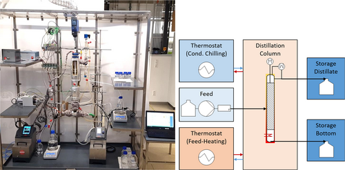
The dosing unit consists of a storage vessel with level sensor, a pump, a Coriolis flow meter, a check valve, and a solenoid valve. This dosing PEA offers the service “dosing” for internal or external operation. In combination of the pump and the Coriolis flow meter, it is possible to dose either per volume or a mass flow rate. Beside these periphery PEAs, the distillation column is a PEA as well, offering the service “distilling”, where the service parameters for the power of the heating rod, the speed of the spinning band, the reflux ratio, and the level set point are offered. There are also different procedures enabling a completely automated start-up and continuous operation of the plant. However, this should not be described in this contribution and was partly presented in 35, 36. In the following, the basic setup, automation, and control for operating the column is described, without going into detail regarding the service architecture.
The whole column and periphery PEAs are installed within a mobile fume hood of 180 cm width, 80 cm depth, and 200 cm height connected to a ventilation system. The feed is fed into the column via a gear pump and a feed preheater at a fixed position in the middle of the active separation height. The liquid flowing down is accumulating in the bottom of the column, where it is heated up by an electric heating rod with a power of 0–250 W. The bottom liquid level is controlled to achieve a constant level. For this, a riser pipe is installed parallel to the bottom in the outlet of the column with a blue sphere inside. The blue floating sphere is always at the same height as the liquid surface inside of the column and is observed by a PixyCAM®, which detects the vertical position of the blue area (see the Supporting Information). A solenoid valve in the outlet of the bottom directly behind the riser pipe keeps the liquid level at a constant set point.
The electrical heating rod partly evaporates the liquid in the bottom, and vapor flows upwards through the active distillation part with the spinning band as internal. At the top of the column the vapor is led to a vapor divider, which either guides the vapor to a product distillate or a reflux condenser, where the vapor is completely condensed. The switching frequency of the vapor divider guiding the vapor between distillate and reflux condenser sets a defined reflux ratio for the column.
When the liquid or the gas load inside of the column is too high, it will lead to flooding equally to common columns 37. Especially with increasing speed of the spinning band, the down-coming liquid phase is retained, and a higher load occurs. Just below the feeding stage the liquid load is at a maximum. This is also the point, where flooding visibly first takes place. Because of the accumulated liquid, the uprising gas is not able to pass, hence, the pressure drop between bottom and head is drastically increasing. In case of flooding, a control mechanism intervenes. The spinning band speed is reduced to a value of 50 rpm to allow the accumulated liquid to flow down in a proper way.
As soon as the pressure drop relaxes to a normal operating value, the spinning band speed is regulated back to 80 % of the last value where flooding occurred. This procedure is implemented as an algorithm in the logic of the programmable logic controller (PLC) and runs fully automatic. The reason of going down to a spinning band speed of 50 rpm after the column was flooded is the sensitivity of mass transport to the spinning band speed. When shutting off the rotation of the band, the separation performance drops, which can be also seen in the head temperature. This is also described in Fig. 6. With this regulation of the spinning band speed, the column is able to deal with flooding itself without any interaction or manual control.
3.2 Spinning Band Geometry
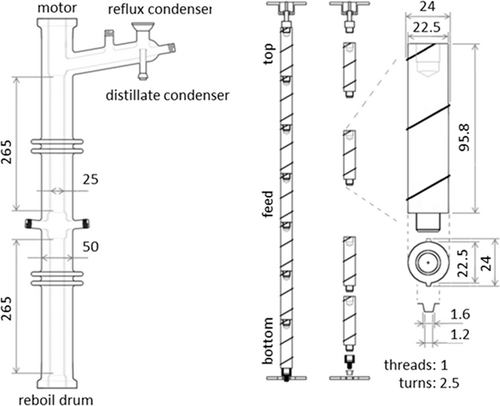
The band design of the investigated column from NORMAG (now Pfaudler Group, Ilmenau, Germany) is chosen to have a good film distribution on the column wall and the band itself. In relation to King and Yates spinning band categories, this spinning band geometry can be classified in category 3. Both phases, liquid and vapor, are stirred, but are not actively hindered in their flow. The helical band, which provides the actual point of contact to the column wall, serves on the one hand for renewing the liquid film on the wall and on the other hand slightly increases the residence time of the liquid. The residence time is increased due to the upwards force similar to an Archimedean screw. Hence, the liquid load related to a certain height is also increased by higher rotation and causes flooding at a certain point. In summary, the optimal operation point regarding the rotation speed of the spinning band is always a tradeoff between throughput and separation efficiency. The exact behavior can be seen later in Sect. 4.
The geometry and design of the band used in this work are displayed in Fig. 2. Even though the column diameter is 25 mm, the cross-sectional area that is flowed through by the fluid is only the 1.25-mm gap between band and column wall (Fig. 2). Due to the high thermal expansion coefficient of PTFE of 130 × 10−6 K−1 38, the diameter and length of the spinning band are increasing during warm-up. The 24-mm diameter of the band increases by 0.25 mm when the temperature rises to 100 °C, e.g., for boiling water. This and the fact of imperfect roundness of the glass column over the whole length are the reason for still leaving an initial small gap of 0.5 mm between the spinning band and the column wall. However, during experiments, a short cut flow of the liquid between the band and column wall was not observed at different positions. The increase in height of the spinning band by 7 mm at 100 °C can be solved by vertical bearings on the shaft between the column and the motor. The resulting cross-sectional area, which is actually flown through in the active section is 93 mm2. With the assumption that the liquid is distributed on both, the glass wall and the spinning band, the resulting specific area is 1600 m2m−3.
4 Results and Discussion
4.1 Hydrodynamics
 (1)
(1) (2)
(2)The velocity is calculated indirectly by the volume flow rate of the vaporized components and the gas density at the respective pressure and temperature.
The operation window of the column is restricted by the gas load and the liquid load equally to conventional columns with structured packings as internals. Additionally, the spinning band speed is dramatically affecting the flooding behavior of the column due to the fact that the liquid accumulates and has a higher residence time for flowing down from top to bottom. This is affecting the liquid holdup and, hence, the pressure drop in the column. This behavior is depicted exemplarily for the n-heptane/methylcyclohexane test system at 100 rpm in Fig. 3.
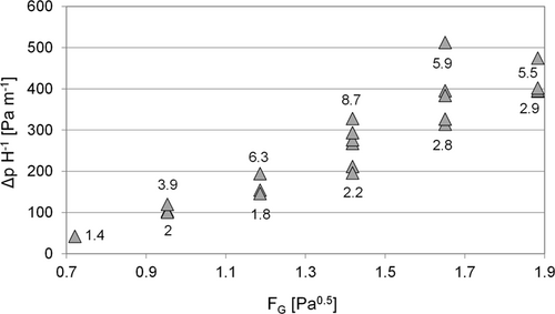
The numbers near the points represent the liquid load at this point. Hence, the lower boundary is the line with nearly the same and lowest possible liquid load, while the upper line is at higher liquid loads. These points were measured by only varying the reflux ratio and boil-up rate for varying the F-factor and liquid load. A feed stream is not introduced to have equal liquid loads and gas factors over the whole column. When a certain gas load and liquid load is reached, the column cannot be operated anymore due to flooding. Equal to common literature, the pressure drop at the flooding point is drastically increasing.
Contrary to common packed columns, a loading point cannot be observed, as the hydrodynamics in the column are very sensitive to the liquid load and spinning band speed. Therefore, if there is a loading point for the column, it is so unstable that either flooding occurs or a normal state linear to the previous pressure drops occurs. To avoid flooding but operating the column near to the flooding point, where mass transfer is intensified, the column is operated at 80 % of the flooding band speed, in order to get best separation results. As mentioned before, the operation window is reduced for higher spinning band speeds. This can be observed well in the following Fig. 4. With higher spinning band speed, the column is flooded earlier for smaller gas factor and lower liquid loads. For achieving the best separation performance, a tradeoff between throughput and separation efficiency must be made at this point.
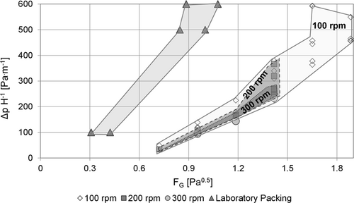
The experiments were conducted with n-heptane/methylcyclohexane, which is a very nonpolar system compared to water or methanol/ethanol. As observed, the spinning band column tends to higher pressure loss for polar systems at same gas factors. Due to the total reflux without introducing feed, the range of liquid load in the smaller gas factor area is limited to the maximum possible reflux flow resulting from the heating power. The trend of decreasing possible gas factors also continues above 300 rpm. For moderate conditions of gas factors below 1 and low liquid loadings, band speeds up to 700 rpm are theoretically possible. However, as described later, no increase of separation efficiency was observed which makes these high band speeds irrelevant.
Compared to a Sulzer laboratory packing type EX 39, the pressure loss of the spinning band column is much lower. Due to visibility reasons, the area of the Sulzer packing is cut off at 600 Pa m−1, but nearly linearly following the visible trend. The small pressure loss of the SBC compared to common packings is reasoned by the nearly unhindered flow of the vapor through the column without changing the flow directions as it is the case for packings. This low pressure loss makes the column very suitable for vacuum applications, which will be presented in further works.
4.2 Mass Transfer
For measuring mass transfer, experiments with infinite reflux and continuous experiments with a distillate product stream were conducted. However, to figure out the steady state in the column, temperatures of bottom and head were observed. Additionally, samples of the bottoms and distillate product streams were taken every 20 min and analyzed to confirm the temperature profile. The starting point t0 is selected in a way that the pressure drop after warming up is at a constant value (Fig. 5).
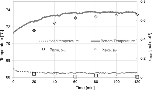
 = 140^W;
  = 3 g min−1; U = 200 min−1.
Due to the small bottom volume of 150 mL, the time until steady state is only 60–80 min for this experiment. After this time, only very small deviations in temperature and concentration occurs, which origins from taking the samples directly out of the bottom disturbing the column operation, although it cannot be generalized from this experiment. However, for all further experiments, temperature and concentration are carefully monitored to ensure that the column has reached the steady state for the mass transfer experiments.
The separation efficiency depends on the rotation speed of the spinning band (Fig. 6a). Increasing the band speed leads to higher separation of the chemicals until a certain critical band speed is reached. Beyond the critical band speed UCrit, the separation efficiency is not getting better, but as observed, it does not decrease. Due to the fact that flooding takes place at a certain band speed and liquid loading, the best operating point for high separation is at around 80 % of the flooding band speed. Additionally, the number of theoretical stages nth was measured to represent the bottom concentration as well (Fig. 6b). For different boiling rates, the same desired trend for higher band speeds can be observed.
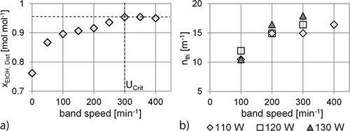
As mentioned above, the concentrations of the distillate product for the MeOH/EtOH system are already reaching over 90 mol %, making this system unsuitable for mass transfer characterization experiments with infinite reflux. It is highly recommended using a test system, where concentrations of bottom and distillate product do not reach higher concentrations than 90 %, because uncertainties in analytics are getting larger for high purities. Additionally, these inaccuracies lead to high uncertainties in the determination of theoretical number of stages, i.e., the McCabe-Thiele method becomes more susceptible to non-idealities in these areas of concentration. Hence, the achievable height equivalent to theoretical plate (HETP) was measured by using the close boiling system n-heptane/methylcyclohexane with a relative volatility of 1.07.
The theoretical number of stages were measured for different gas factors between 0.7 and 1.5 Pa0.5, which is equal to the heating power of 70–100 W for the n-heptane/methylcyclohexane system. The resulting HETP values are given in Fig. 7.
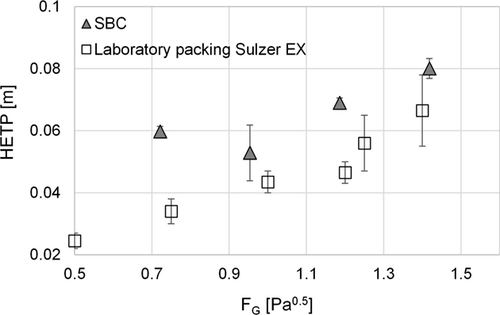
The achieved HETP values are varying from 5 to 8 cm for the different gas factors. It has to be mentioned that the given values especially for the gas factor of 0.95 Pa0.5 are mean values of different band speeds and liquid loadings, for the reason of clarity. Generally, the behavior as shown before still applies, for higher band speeds until a certain critical band speed, the separation efficiency gets better. Additionally, for lower gas factors the separation efficiency increases as well. This can be explained with the boiling rates and is similar to common columns. For higher boiling rates, more of the heavy boiling component is evaporated, which leads to a worse separation. In addition, the higher gas velocities contribute to a shorter contact between gas and liquid film in the SBC.
Compared to common laboratory packings, e.g., the laboratory packing EX of Sulzer 39, 40, the SBC achieves almost similar HETP values in the region above the F-factor 0.9 Pa0.5. Below, the Sulzer packing attains better results, which is due to the fact that this packing is specially designed for low gas and liquid loads. However, the total amount of chemicals necessary for such a distillation column with diameters between 20 and 80 mm is much higher than that of the SBC. Additionally, the spinning band speed as control parameter enables further control strategies that allow this column to adapt itself to variable feed flow rates and compositions. Results regarding this are published in further articles.
5 Conclusion and Outlook
A continuously operated spinning band column was presented and characterized with two chemical systems. Within the framework of modular plants, this column can serve as a nearly autonomous process equipment for distillation due to its automation and service architecture in combination with a module type package. The column was characterized with two test systems, the polar system methanol/ethanol and the nonpolar system n-heptane/methylcyclohexane. The hydrodynamic behavior of the column was examined, and operation windows were pointed out, especially regarding the spinning band speed. In mass transfer experiments, within 60 min steady state was reached and HETP values between 5 and 8 cm can be achieved for different gas factors and liquid loads at total reflux. Due to the low volume of the bottom with only 150 mL, feasibility studies can be done with very low material input, but still in continuous operating mode.
In further investigations, feasibility studies for unknown component systems should be better pointed out by distilling chemical systems with uncertain thermophysical data to generate knowledge about the separation. Additionally, interoperability with further process equipment assemblies will be investigated by connecting the distillation to other downstream or analyzing units such as an extraction column or a Raman spectrometer. These combinations are feasible by using the module type package concept and proving the service architecture for the distillation column. Furthermore, the spinning band column with its low pressure drop is well suited for vacuum distillation, opening a new operation window and application field. Hence, the implementation of a vacuum unit is targeted. Besides this, the geometry and design of the spinning band is further investigated, such as the angle of the spiral and a flexible feeding system to the column.
Supporting Information
Supporting Information for this article can be found under DOI: 10.1002/ceat.202000602. This section includes additional references to primary literature relevant for this research 41-45.
Acknowledgements
The BMWi is acknowledged for funding this research as part of the ENPRO2.0 initiative (Support code: 03ET1517B). Open access funding enabled and organized by Projekt DEAL.
The authors have declared no conflict of interest.
Symbols used
-
- AQ [m2]
-
cross section
-
- FG [Pa0.5]
-
F-factor/gas factor
-
- h [m]
-
height
-
- ΔhLV [kJ kg−1]
-
evaporation enthalpy
-
 [g min−1]
 -
mass flow of feed
-
- nth [m−1]
-
theoretical number of stages
-
- Δp [Pa]
-
pressure drop
-
 [W]
[W] -
electric heating
-
 [W]
[W] -
heat loss
-
- U [min−1, rpm]
-
spinning band speed
-
- uL [m3m−2h−1]
-
liquid load
-
- wi [kg kg−1]
-
weight fraction of component i
-
- wG [m s−1]
-
gas velocity
-
- xi [mol mol−1]
-
mole fraction of component i
Greek letter
-
- ρG [kg m−3]
-
density of the gas phase
Abbreviations
-
- EtOH
-
ethanol
-
- FEA
-
functional equipment assembly
-
- HETP
-
height equivalent of a theoretical plate
-
- MP
-
modular plant
-
- MTP
-
module type package
-
- OPC-UA
-
open platform communication unified architecture
-
- PEA
-
process equipment assembly
-
- PLC
-
programmable logic controller
-
- POL
-
process orchestration layer
-
- PTFE
-
polytetrafluoroethylene
-
- SBC
-
spinning-band column


