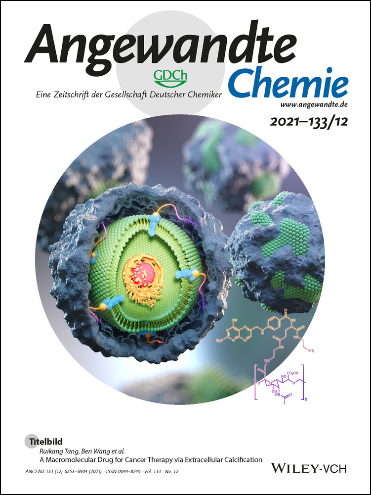
Embedment of Quantum Dots and Biomolecules in a Dipeptide Hydrogel Formed In Situ Using Microfluidics
Abstract
As low-molecular-weight hydrogelators, dipeptide hydrogel materials are suited for embedding multiple organic molecules and inorganic nanoparticles. Herein, a simple but precisely controllable method is presented that enables the fabrication of dipeptide-based hydrogels by supramolecular assembly inside microfluidic channels. Water-soluble quantum dots (QDs) as well as premixed porphyrins and a dipeptide in dimethyl sulfoxide (DMSO) were injected into a Y-shaped microfluidic junction. At the DMSO/water interface, the confined fabrication of a dipeptide-based hydrogel was initiated. Thereafter, the as-formed hydrogel flowed along a meandering microchannel in a continuous fashion, gradually completing gelation and QD entrapment. In contrast to hydrogelation in conventional test tubes, microfluidically controlled hydrogelation led to a tailored dipeptide hydrogel regarding material morphology and nanoparticle distribution.
Introduction
Dipeptides are widely used as smart building blocks in supramolecular assemblies in nanoscience due to their structural simplicity, flexibility, and variety of accessible structures depending on the assembly conditions.1 Dynamic assembly determines key material properties, such as shear-thinning,2 self-healing,1b structure modulation,3 and controlled organization,4 desirable for applications in nanotechnology,5 photoelectricity,6 and biomedicine.5a, 7 Still, a fundamental challenge in dipeptide assembly as well as in supramolecular chemistry in general, is how to precisely control the self-assembly process and embedding active compounds like quantum dots (QDs) or biomolecules at the same time.8
In conventional macroscopic flasks or vials, supramolecular assembly spontaneously occurs under equilibrium due to mixing in bulk solution.9 Focusing on the molecular level, the assembly process under these circumstances usually proceeds randomly in time and space, resulting in an average macroscopic state with local structural defects.9 However, since assembly processes can be accompanied by phase separation, and spatiotemporal inhomogeneities of the chemical environments, precise control of the assembly pathway is crucial to avoid ill-controlled physical and chemistry properties and thus subpar material performance.10 This is especially true for dipeptide materials in nanotechnology, yet it is still an unmet challenge to achieve control over their growth and the distribution of functional groups and compounds within the self-assembled supramolecular structure.3a
Exemplarily, the dipeptide N-fluorenylmethoxycarbonyl diphenylalanine (Fmoc-FF) predissolved in DMSO can spontaneously self-assemble into a fibril-based hydrogel after solvent exchange with water.3b, 11 As a low-molecular-weight gelator (LMWG), Fmoc-FF nanofibers allow for loading multiple organic molecules, enzymes or inorganic particles by simply embedding them in the gel without permanent covalent bonds.12 Especially, the unique biocompatibility, biodegradation, self-healing, and shear-thinning properties of Fmoc-FF-based hydrogels path the way for applications in biomedicine as injectable carriers.2, 13 However, Fmoc-FF-based assembly combined with the entrapment of multiple functional molecules has, to date, almost exclusively been completed on macroscopic scale and investigated by varying concentrations or solvents in a quiescent sate. To exert precise control over self-assembled structure formation, microfluidics is the method of choice.3a, 14
Here, we use continuous-flow microfluidics to form a Fmoc-FF-based hydrogel entrapping hydrophilic cadmium telluride quantum dots (CdTe QDs) and organic porphyrins in one system. As typical inorganic particles, QDs are selected to investigate the process of dynamic entrapment inside microchannels15 due to the remarkable photoluminescent properties, and their size-dependent fluorescent intensity.16 Besides, porphyrins have been employed as typical light-harvested pigments being widely used as biocompatible photosensitizers, e.g., in photodynamic therapy.17 We expect that inorganic QDs can cooperate with organic porphyrins in one integrated system to achieve energy transfer.16a, 18 As a result, we find Fmoc-FF-induced self-assembly and hydrogel formation, respectively, can occur at a dynamic DMSO–water interface owing to π–π interactions, aiding QDs and the porphyrin to be integrated in one hydrogel. Microflow control enables porphyrin monomers to interact continuously with as-formed Fmoc-FF nanofibers at the co-flowing solvent interface, and QD nanoparticles to be entrapped by the Fmoc-FF/porphyrin nanofibers. The Fmoc-FF assembly process is supported by a meandering microchannel connected to the Y-shaped junction that not only exhibits curved, but also narrow channel sections19 to more efficiently mix the hydrogel precursors for optimized hydrogelation. Owing to the shear-thinning property of Fmoc-FF hydrogels,2 the hydrogel continuously formed under laminar flow conditions is homogenous regarding the entrapment of QD nanoparticles, compared to conventional mixing of the same precursors at macroscopic scale. As the hydrogel precursor concentrations are chosen such that the as-formed hydrogels do not clog the microchannels of our microfluidic device, it can be continuously collected from the outflow port for further analysis and potential application, e.g., as a basis for injectable biomedicine.13 The overall microfluidics layout is optimized for complete mixing and particularly suitable to also study as-formed hydrogels at different positions inside the microfluidic device. Thus, hydrogels with a variety of morphologies on the nanoscale can be obtained depending on initial precursor concentrations at different collection positions inside the microchannel. Moreover, by stopping the hydrogel flow, a static hydrogel structure with the dimensions of the microchannel network remains on the surface of the microchannel substrate. By analyzing the nanoscale morphology of the microchannel-shaped, Fmoc-FF-based hydrogel at different positions of the microfluidic device, we capture the dynamic assembly and QDs entrapment processes by a series of scanning electron microscope (SEM) images. The microfluidic platform thus provides insight into the dipeptide assembly mechanism and can be utilized for screening the structure formation and material properties of dynamically formed nanomaterials, which is crucial for tailored material platforms and specialized applications in light harvesting,8a, 20 energy transfer,6, 21 and bio-nanotechnology.8a, 22
Results and Discussion
First, two different porphyrins, 5,10,15,20-(tetra-4-carboxyphenyl)porphyrin (TCPP) and 5,10,15,20-(tetra-4-aminophenyl)porphyrin (TAPP), which exhibit different polarities due to either carboxyl or amino groups are employed to investigate whether these differences have an impact on the morphology of formed nanofibers (Figure 1 a). As inorganic nanoparticle basis for investigating their embedment in Fmoc-FF hydrogels,16a, 23 we use four types of water-soluble CdTe QDs exhibiting fluorescent colors from green (520 nm), yellow (570 nm), orange (610 nm) to red (710 nm) with increasing diameters from less than 10 nm to 20 and up to 30 nm.
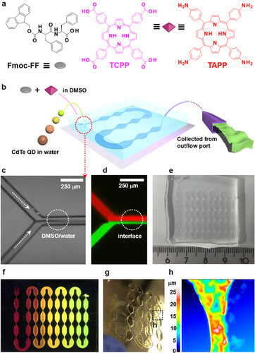
a) Chemical structures of Fmoc-FF, TCPP and TAPP. b) Continuous fabrication of a supramolecularly assembled hydrogel by microfluidics. c) Optical microscopy and d) fluorescence images of the dynamic DMSO/water interface (TCPP and Fmoc-FF were predissolved in DMSO, QD-520 were dispersed in water). Red indicates TCPP, green indicates QD-520. e) Photograph of the microdevice employed in this study. f) Fluorescence microscopy image of the Fmoc-FF/QD-520/QD-570/QD-610/QD-710 hydrogel formed in a microdevice and illuminated at 365 nm. g) Hydrogel remaining on the glass substrate after removal of the PDMS cover. h) Selected surface topography image of the Fmoc-FF/TCPP/QD-520 hydrogel shown in (g).
To form the hydrogel, Fmoc-FF and one type of porphyrin (TCPP or TAPP) are predissolved in DMSO with concentrations of Fmoc-FF at 10 mg mL−1 constituting the organic phase. Single-type QDs are presuspended in water at a concentration of 5 mg mL−1 and diluted when necessary. In a typical experiment, a Y-shaped microfluidic junction connected to a meander-like outflow channel is employed for continuously generating the desired hybrid hydrogel (Figure 1 b,e and f). Precursor solutions of Fmoc-FF and TCPP (or TAPP) as well as the QDs suspension are injected into opposite branches of the microchannel Y-junction with controlled volumetric flow rates adjusted by high-precision syringe pumps (Figure 1 b). After co-injecting the aqueous and organic phase, a dynamic co-flowing interface forms between DMSO and water (Figure 1 c and d), at which hydrogel assembly occurs through noncovalent interactions spontaneously due to diffusion-based mixing. The hydrogelation process proceeds inside a consecutive meander-like microchannel, whose length is optimized to ensure quantitative conversion of both precursor phases at the outflow port of the flow cell (Figure 1 b right).24 Alternatively, instead of collecting the shear-thinning QD-doped Fmoc-FF-porphyrin hydrogel, the hydrogel filling out the volume of the meander-shaped microchannel can remain inside the microfluidic device for three days to ensure complete hydrogelation throughout the flow cell. Upon removal of the poly(dimethylsiloxane) (PDMS) cover of the microfluidic device, the hydrogel structure remains on the glass substrate (Figure 1 g and h), e.g., Fmoc-FF/TCPP/QDs, which can be used for further characterization of optical properties and structures.
Next, we compare the interactions of two porphyrins (TCPP and TAPP) and Fmoc-FF premixed in bulk and dynamically mixed inside microfluidic channels. Without QDs dispersed in water, we examine the optical properties of hydrogel precursor solutions and their assembly into hydrogels using absorption and fluorescence spectroscopy (Figure 2 b to d, Figure S1). As shown in Figure 2 b and c, both TCPP and TAPP fully dissolve in DMSO, exhibiting intense Soret bands at approx. 420 nm, and typical Q bands in a range from 500 to 700 nm. After transfer into water, a broader spectral bandwidth as well as a slight red or blue shift is observed because of H-/J-aggregate formation. The change of microenvironment polarity around the porphyrin from DMSO to water during hydrogel formation leads to a significant color change (images inserted in Figure 2 b and c).25 The Fmoc-FF/TAPP hydrogel exhibits a strong red shift not only compared to TAPP solutions, but also aggregates, indicating its potential application in near infrared-dependent photosensitized therapy, for instance.17b, 26 Corresponding fluorescence spectra of porphyrin monomers, porphyrin aggregates, and Fmoc-FF/porphyrin hydrogels are shown in Figure 2 d, indicating that the porphyrin TCPP maintains their original fluorescent wavelength. In porphyrin aggregates, there is a dramatically quenched fluorescence signal due to π–π stacking of TCPP or TAPP. However, this quenching effect is weakened by increasing the Fmoc-FF concentration in the supramolecular hydrogel, indicating that porphyrins and dipeptide likewise participate in self-assembly on molecular level.17a Herein, a plausible assembly model is shown in Figure 2 a to explain molecular interactions in nanofiber. The stability of the co-assembled nanofibers mainly originated from the Fmoc-FF-based self-assembly through hydrophobic interactions and π-stacking. In addition, multiple interactions contribute to the stability of such system, e.g., due to π-stacking among porphyrins, π-stacking between Fmoc-FF and porphyrins, hydrophobic effects, and electrostatic interactions between Fmoc-FF and TAPP.27
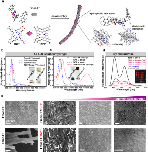
a) Co-assembly of the dipeptide and porphyrins. b, c) UV/Vis spectra of the Fmoc-FF hydrogel, the porphyrins dissolved in DMSO (as the monomer), the porphyrins in water (as aggregates), and the Fmoc-FF/porphyrin hydrogels (images of TCPP in DMSO solution, TCPP/Fmoc-FF co-assembled hydrogel, TAPP in DMSO solution, and TAPP/Fmoc-FF co-assembled hydrogel are shown as inserts). d) Emission spectra of Fmoc-FF hydrogel, TCPP dissolved in DMSO (as the monomer), TCPP in water (as aggregates), and Fmoc-FF/porphyrin co-assembled hydrogels with different concentrations of Fmoc-FF (fluorescence microscopy image of Fmoc-FF/TCPP co-assembled hydrogel fabricated by microfluidics after removing the PDMS cover is shown as an insert). e) SEM images of Fmoc-FF hydrogels at different magnifications, and Fmoc-FF/TCPP and Fmoc-FF/TAPP hydrogels with increasing concentrations of TCPP and TAPP of 32, 632, and 1897 mM (from left to right). All scale bars denote 200 nm.
Next, we investigate the morphology of all Fmoc-FF/porphyrin hydrogels prepared in bulk by a series of SEM images of Fmoc-FF/TCPP and Fmoc-FF/TAPP (Figure 2 e). Coinciding with reports for simple Fmoc-FF hydrogels, our Fmoc-FF/porphyrin hydrogels consist of nanofibers intertwined with each other.3b In addition, the Fourier transform infrared (FTIR) spectrum of Fmoc-FF hydrogels with and without porphyrins exhibit a peak at 1660 cm−1 (Figure S2), which is consistent with a β-sheet structure and possibly an antiparallel arrangement.3b The lowest concentrations (32 mM) of Fmoc-FF/TCPP and Fmoc-FF/TAPP show no significant difference regarding their micro- and nanoscale morphology, as studied by SEM imaging. By analyzing the fiber width of Fmoc-FF/TCPP and Fmoc-FF/TAPP by atomic force microscopy (AFM), only minor deviations in their nanofiber width are found (Figure S3). However, with increasing concentration of porphyrins in the hydrogel precursor mixture, a mixed morphology of nanofibers and stratified aggregates is observed. Additional fluorescence intensity statistics of TCPP show (Figure S4) that higher concentrations of porphyrin in the hydrogel formulation cause an extra stacking of TCPP. Considering that TCPP can also self-assemble into nanostructures or irregular aggregates on its own, a very high concentration of TCPP may lead to self-assembly independent of nanofiber formation in our experiments. Despite the remarkable capability of Fmoc-FF to integrate organic porphyrins during Fmoc-FF/porphyrin hydrogel formation indicated by any leakage of porphyrin detected in the supernatant water in bulk experiments, a stable hydrogel cannot be formed neither in bulk nor in microfluidic channels at high concentrations of QDs, e.g., 5 mg mL−1 (Figure S5). Beyond that, once the Fmoc-FF/porphyrin hydrogel forms, nearly no leakage of porphyrin can be detected in water, indicating the remarkable capability of Fmoc-FF binding organic porphyrins.
A series of water-soluble CdTe QDs coated with carboxyl groups is chosen as fluorescent inorganic model for entrapment investigations (Figure S6a). Since the fluorescence intensity of the TCPP hydrogel is much higher than for TAPP when integrated into a Fmoc-FF hydrogel, the following entrapments are all based on the Fmoc-FF/TCPP system. To investigate the encapsulation of QDs with different sizes in the Fmoc-FF/TCPP hydrogels, we select four different fluorescent colors of QDs: green (520 nm), yellow (570 nm), orange (610 nm), and red (710 nm) with increasing QD diameters from less than 10 nm to 20–30 nm.23 Being predispersed in water, QDs are injected into microfluidic devices, and entrapped by Fmoc-FF in the hydrogel formation process under continuous flow. All types of QDs employed can be entrapped in hydrogels during microfluidic processing by successively feeding in different QDs (Figure S6b and 1f). The normalized fluorescent emission spectra of QDs compared to QDs encapsulated in Fmoc-FF/TCPP hydrogels are shown in Figure 3 f. The maxima of the emission spectra after QD encapsulation are red-shifted (approximately 2 nm for QD520 and QD570, 10 nm for QD610, and 14 nm for QD710) compared to free QDs in water. The red-shifts in the emission spectra of encapsulated QDs occur due to the aggregation of QDs. The QDs are not embedded inside the dipeptide fibril assembly, but instead, become merely passively entrapped in the interspace of the Fmoc-FF/TCPP fibril network or remain on the surface of the nanofibers (Figure 3 a–e).23
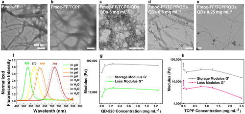
a–e) TEM images of Fmoc-FF hydrogel (a), Fmoc-FF/TCPP hydrogel (b), and Fmoc-FF/TCPP/QD-520 hydrogels with different concentrations of QD-520 in water as fabricated by microfluidics (c–e). f) Fluorescence spectra of Fmoc-FF/TCPP/QDs bulk hydrogels and QDs dispersed in water. g, h) Rheological characterization of Fmoc-FF/TCPP/QD-520 bulk hydrogels with different concentrations of QD-520 (g), and Fmoc-FF/TCPP bulk hydrogels with different concentrations of TCPP (h). All scale bars denote 100 nm.
Focusing on the entrapment of CdTe QDs with a maximum emission at 520 nm (QD-520) in Fmoc-FF/TCPP hydrogels, distinct fluorescent colors can be detected under UV-light irradiation ranging from green to orange depending to the concentration ratio between QD-520 and TCPP (Figure S7), indicating that organic TCPP and inorganic QDs both exist in the hydrogel and exhibit an overlay color.28 Notably, especially when being repeatedly swollen in water, almost no QDs are detected by UV spectroscopy in the supernatant of the hydrogel, which further confirms their containment by the Fmoc-FF hydrogel.
Next, to detail on the distribution of QDs in the Fmoc-FF/TCPP hydrogels made by continuous-flow microfluidics, we investigate the supramolecular organization between QDs and Fmoc-FF/TCPP fibrils. We find that QDs attach and distribute along the naked Fmoc-FF/TCPP fibrils (Figure 3 b), even at the relatively high QD concentration studied herein (5 mg mL−1 in water). To explore the influence of TCPP and QDs on the mechanical properties of the supramolecularly assembled Fmoc-FF gels, we conduct rheology measurements on a series of hydrogels prepared from Fmoc-FF in bulk with different concentrations of TCPP or QDs. As shown in Figure 3 g,h, and S8, the stiffness decreases with increasing concentrations of TCPP in the co-assembled hydrogel. However, the stiffness of the co-assembled hydrogel increases with the addition of QDs and reaches a plateau after an initial steep rise.13 TCPP is incorporated into the nanofibers with Fmoc-FF, resulting in a weakening of interactions between fibrils inside the co-assembled hydrogel. This leads to a reduction of the shear modulus with increasing TCPP concentration. On the contrary, a reasonable explanation for the different behavior with increasing concentrations of QDs may be that the QDs cause a hydrogel stiffening by forming multiple contacts between the fibers.
Beyond investigating the general interactions of QDs being loaded into the Fmoc-FF/porphyrin-based hydrogel system in bulk, we further investigate the dynamic entrapment of QD inside microfluidically prepared hydrogels. For that, Fmoc-FF/TCPP in DMSO and QDs in water are co-injected from the inflow ports 1, 2 (Figure 4 a). Then, diffusion-based mixing and hydrogelation occurs in the meander-like outflow channel, whose repeated tapering also enables us to study the influence of flow orientation on fiber formation (Figure 4 a–c). Remarkably, the parallel alignment of Fmoc-FF-based nanofibers improves due to increased flow rates in these microchannel sections.19 Quantitative mixing of both precursor streams is achieved inside the microfluidic device by tailoring the outflow channel length based on the analysis of hydrogels collected at different microchannel positions. The number of repeated constrictions, broad sections, and turns of the meander-shaped outflow channel is optimized to guarantee a good mixing. As shown in Figure 4 b, employing equal flow rates for both phases from 30 μL h−1 to 1000 μL h−1, the two phases show sufficient mixing after passing through approximately 20 narrow constrictions (Figure 4 c) and 5 bends (Figure 4 d and e). As shown in Figure 4 c, the supramolecular assemblies particularly align in the microchannel flow constrictions. We attribute this to the increased shear stress provided by the flow in this region. Especially in curved sections (Figure 4 d and e), a unique organization of Fmoc-FF appears composed of both conventional twisted nanofibers and straight nanofibers. We attribute this complex morphology to the unique three-dimensional mixing profile in these microchannel sections29 (Figure 4 f).
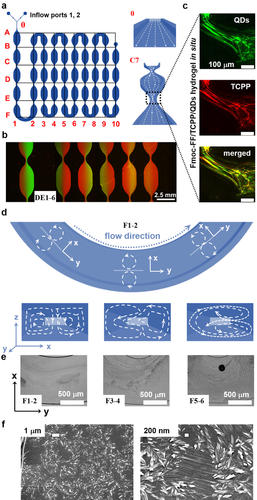
a) 2D geometric architecture of microchannels. Right: Illustration of flow direction in the microfluidic device. b) Fluorescence microscopy images of region DE1-6 labeled in (a); green corresponds to QD-520 in water, and red to TCPP in DMSO. c) After 3 days and removal of the PDMS cover, CLSM images were recorded of the Fmoc-FF/TCPP/QD-520 hydrogel at the narrow position in region C7. d) Illustration of region F1-2 in (a). Below: Flow direction in microchannels corresponding to positions above.29a e) Optical microscopy images of different positions shown in (a), showing dynamic flow and mixing of water and DMSO. f) SEM images of Fmoc-FF formed in situ in region F1-2 in (a).
Next, we remove the microchannel-bearing PDMS part of the microfluidic device and characterize the morphology of the Fmoc-FF/TCPP/QD hydrogels at different locations inside the flow cell to investigate the QD entrapment process during nanofiber formation. To label specific locations corresponding to time steps in the entrapment process, we overlay the microchannel-shaped hydrogel with a two-dimensional coordinate system (Figure 5 a). In position D1, nanofibers are not detected because of yet insufficient mixing, while in F7, nanofibers form with predominant orientation along the flow axis compared to D2, E7, and C9. As shown in segment D2, E7, C9 and the hydrogel collected from the device's outflow port, QDs gradually attach to the nanofiber surface and are eventually uniformly entrapped into the hydrogel networks. In contrast to hydrogel formation in macroscopic reaction vessels, employing co-flow microfluidics prevents the assembly of QDs into aggregates due to a defined mixing profile across the outflow microchannel.
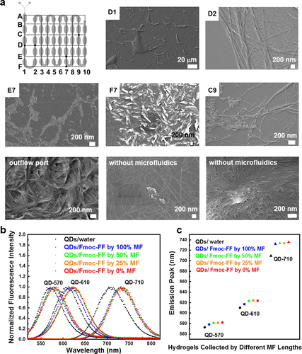
a) SEM images of Fmoc-FF/TCPP/QDs assembled in different regions of the microfluidic device. b) Normalized emission spectra of QDs dispersed in water, Fmoc-FF/QDs hydrogel fabricated by microfluidics (MF), and Fmoc-FF/QDs hydrogels fabricated without microfluidics from the same reaction volume of 100 μL. c) Emission peaks from fitting curves in (b). To collect hydrogel samples at 100, 50, and 25 % of the total length of the outflow channel, tubing was inserted into the flow cell at position B10, B5, or B3 labeled in (a).
We also add additional collection ports into the microchannel-bearing PDMS part of the flow cell at different positions of the outflow channel to characterize the Fmoc-FF/TCPP/QD regarding different flow histories and mixing states and thus different gelation times. As shown in Figure 5 b and c, Fmoc-FF/TCPP/QDs hydrogels that completely pass through the flow cell upon characterization exhibit less red shift in the emission spectrum compared to those collected at outflow ports closer to the Y-junction or those obtained by conventional mixing without microfluidics of the same volume (red spot in Figure 5 c).23 As the QDs emission wavelength depends on the particle size, and a red shift of QDs suspensions indicates aggregate formation, it confirms that by using microfluidics QDs are more uniformly distributed in the hydrogel matrix,16a, 30 which may exemplarily contribute to the challenge of uniformly loading injectable, supramolecular hydrogels in the area of biomedicine.6, 13 Although, uniform QD distribution in bulk hydrogels can also be achieved in macroscopic test tubes by vigorous vortexing, microfluidics with its tailored microchannel architecture and flow pattern formation provides superior reproducible experimental conditions.
To investigate the functional interactions between porphyrins and QDs in our hybrid hydrogels, we utilize Förster resonance energy transfer (FRET) to investigate the interaction of organic and inorganic parts of our hydrogel system.31 These measurements also provide insights in the supramolecular organization of Fmoc-FF/TCPP/QDs hydrogels fabricated by microfluidics.31, 32 The spectral overlap between QD emission and porphyrin absorption (Figure 6 b) are a prerequisite for the energy transfer from QDs (donor) to porphyrins (acceptor) (Figure 6 a). Herein, the fluorescence signals of Fmoc-FF hydrogels with varying concentration ratios of TCPP and QDs are compared. As shown in Figure S4, an excess of TCPP (over 100 μM) deposited in the form of aggregates outside of the nanofibers (Figure 2 e, right) causes a decrease in fluorescence intensity by self-aggregation-induced quenching. To avoid fluorescence quenching at high concentrations of TCPP, all further FRET experiments are performed at concentrations below 100 μM. We then record the absorption spectra and FRET efficiency of four differently colored QDs, as shown in Figure 6 e. For fixed concentrations of Fmoc-FF and QDs, signals corresponding to QDs at their maximum emission wavelength decrease when excited at 270 nm with increasing concentrations of TCPP. A series of gradually varying fluorescence emission curves for an increasing amount of TCPP is shown in Figure 6 c using QD-570 as a representative example. On the other hand, for fixed concentrations of Fmoc-FF and TCPP, the emission peaks of TCPP at 660 nm and 720 nm increase when excited at 270 nm with increasing concentrations of QDs due to higher energy input (Figure 6 d). A typical confocal microscopy image confirming the FRET effect in our hydrogel system is depicted in Figure 6 f. After being bleached by illumination, the acceptor TCPP exhibits a decreased fluorescent signal, while an increased green signal of donor QDs emerges due to inhibited energy transfer from QDs to TCPP (cf. Figure 6 f). However, for concentrations of QDs of more than 1 mg mL−1 (Figure S9), additional QDs do not lead to a further increase of TCPP fluorescence and FRET. The results shown in Figure 3 c–e may provide a reason for this observation. Once the surface of nanofibers is fully occupied by QDs (Figure 3 c), excess QDs can only be entrapped in the solvent swelling the hydrogel and interact with the Fmoc-FF nanofibers at extremely small distances (normally less than 10 nm).26, 28 As the typical FRET effect is strongly dependent on the distance between donor and acceptor, QDs in the solvent cannot contribute to energy conversion. Therefore, tuning concentration ratios among different components of our hydrogel system is crucial to enhance the observed FRET effect, which can be easily controlled by the inflow velocity of hydrogel precursor solutions.
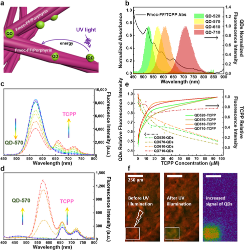
a) Energy transfer in Fmoc-FF/porphyrin/QDs hydrogels. b) Absorbance spectra of Fmoc-FF/TCPP hydrogel and emission spectra of quantum dots. c) Emission spectra of Fmoc-FF/TCPP/QD-570 hydrogel excited at 270 nm with a fixed concentration of Fmoc-FF and QD-570 while increasing the concentration of TCPP. d) Emission spectra of Fmoc-FF/TCPP/QD-570 hydrogel excited at 270 nm with a fixed concentration of Fmoc-FF and TCPP while increasing the concentration of QD-570. e) Fluorescence signal of QD-520, QD-570, QD-610, and QD-710 against concentrations of TCPP in hybrid hydrogels. f) CLSM images of the Fmoc-FF/TCPP/QD-570 hydrogel collected from the microfluidic device. Images were merged by the red signal of TCPP (acceptor) and the green signal of QD-570 (donor). By bleaching the acceptor, an increase in the green signal is observed.
Conclusion
Summarizing, we have exploited a new approach for the continuous fabrication of dipeptide-based hydrogels and hydrogel/QD-hybrid materials by continuous-flow microfluidics. In the microchannels of our microfluidic system, inorganic QDs with different sizes and organic porphyrins could be entrapped with a uniform organization in the Fmoc-FF-based hydrogel formed by supramolecular assembly. Rheological analysis revealed that the organic porphyrin TCPP was co-assembled into nanofibers with Fmoc-FF, while inorganic nanoparticles were entrapped and adsorbed on the surface of the nanofibers. The dynamic assembly could be monitored inside the microfluidic channels in situ, showing that QDs were gradually entrapped and eventually formed a hybrid hydrogel exhibiting uniform entrapment of QDs. Thus, by combining “bottom-up” self-assembly and “top-down” microfluidic control, the co-assembly of multiple components could be precisely controlled avoiding heterogeneities that are typically encountered in macroscopic hybrid gel formation. Furthermore, energy transfer by FRET was confirmed in our supramolecular hybrid system, exhibiting energy transfer from inorganic QDs to the organic TCPP, further illustrating the extreme small distance between them and the superiority of low-molecular-weight dipeptide hydrogelator to efficiently entrap and integrate QDs. Moreover, by tuning the mixing ratios of the organic and aqueous phases in the microfluidic platform, hydrogels with gradually tunable properties within one material were obtained, indicating the feasibility of microfluidics-based continuous hydrogel formation. Accordingly, the formation of dipeptide-based multicomponent hydrogels opens up new possibilities for applications in biomedical devices, photodynamic therapy, or continuous bioprinting of these hybrid gels.
Acknowledgements
J.T. thanks the Federal Ministry of Education and Research (BMBF, Biotechnologie2020+ Strukturvorhaben: Leibniz Research Cluster, 031A360C) and the German Research Foundation (DFG, Research Training Group 1865 “Hydrogel-based Microsystems”). J.T. also receives funding from the European Research Council (ERC) under the European Union's Horizon 2020 research and innovation program (Grant agreement No. 852065), and he acknowledges the Young Investigator Program of the Technische Universität Dresden. J.L. acknowledges financial support from the National Nature Science Foundation of China (No. 21961142022). Y.L. is supported by the Alexander von Humboldt Foundation as a postdoctoral researcher. We thank Dr. Petr Formánek and Uta Reuter for TEM measurements, Birgit Urban for FTIR measurement, and Andreas Janke for AFM characterization and calculation of hydrogel nanofiber dimensions (all Leibniz IPF Dresden). Open access funding enabled and organized by Projekt DEAL.
Conflict of interest
The authors declare no conflict of interest.


