Hydrodynamic Trapping of Particles in an Expansion-Contraction Microfluidic Device
Abstract
Manipulation and sorting of particles utilizing microfluidic phenomena have been a hot spot in recent years. Here, we present numerical investigations on particle trapping techniques by using intrinsic hydrodynamic effects in an expansion-contraction microfluidic device. One emphasis is on the underlying fluid dynamical mechanisms causing cross-streamlines migration of the particles in shear and vortical flows. The results show us that the expansion-contraction geometric structure is beneficial to particle trapping according to its size. Particle Reynolds number and aspect ratio of the channel will influence the trapping efficiency greatly because the force balance between inertial lift and vortex drag forces is the intrinsic reason. Especially, obvious inline particles contribution presented when the particle Reynolds number being unit. In addition, we selected three particle sizes (2, 7, and 15 μm) to examine the trapping efficiency.
1. Introduction
Microfluidics has greatly interested many researchers in recent years, and has been widely used in the areas of nanomaterials preparation, pharmaceutical analysis, protein engineering, and so on [1–4]. Manipulation and sorting particles suspended in microflow are often applied to biomedical area. Separating targeted particles from the detect solution is an important process. Not a few techniques such as membrane filtration, fluorescence, or magnetic particle sorting were developed in recent years, and they have a wide range of applications [5–7]. However, microfluidic-based devices introduce several advantages, such as higher efficiency, lower sample buffer consumption, fine spatial resolution, and lower cost [8]. In addition, microfluidic-based device can trap particles based on their intrinsic physical characteristics. Hydrodynamic manipulation of particles in an expansion-contraction microfluidic device is a passive method by harnessing microchannel geometrical effects and nonlinear hydrodynamic forces and needs not any application of external force leading to a complicated device structure.
Passive methods used to trapping particles by exerting hydrodynamic force are arising in microfluidic devices. The main approaches are the cross-stream migration of suspended particles in confined flows and microvortical flow. The microvortex generated in sudden expansion is of great importance for particle manipulation. Researchers have gained some beneficial research results [9–11] in the theoretical analysis and experimental investigations on the formation of vortices in different microchannel configurations. Jiang et al. [9] numerically investigated the flow field under various inlet flow rates and cavity structures and then systematically studied the flow features of the vortex and Dean flow in this channel by LBM. Bălan et al. [10] investigated the dynamics of the vortices generated in the vicinity of Y- and T-microbifurcations with one occluded branch. The velocity distribution and streamlines were obtained through the experiments and numerical simulations. Karimi et al. [11] concentrated their study on the dynamical mechanisms of cross stream migration particles in shear and vortical flows. Tsai et al. [12–14] found that Reynolds number and aspect ratio are both influential factors for flow patterns in a suddenly expansion microchannel. Park et al. [15] developed a kind of microfluidic method for focusing on microparticles through the combined use of inertial lift forces and turbulent secondary flows in a patterned microchannel. Furthermore, some particles trapping applications of the microvortices in an expansion-contraction microchannel have been presented in recent years [16, 17]. According to their research work, in the contraction part, particles flow under the balance of shear-gradient lift force and wall effect lift force. When the particles move into the expansion part, wall effect lift force disappears and the shear-gradient lift force leads particles to the vortex formed in the orifice. Lee’s group [18, 19] demonstrated a blood plasma separation scheme by employing the unilateral contraction-expansion array microchannel with a low aspect ratio. Small particles are driven predominantly by Dean drag force while the larger ones are lifted by the inertial force and stay close to their previous positions, leading to the isolation of different size particles. The inlet flow rate should be appropriately controlled to avoid particles migration into the vortex in the orificial under a high flow rate.
In the present research, microvortex in the expansion-contraction microchannel is numerically studied in order to understand the particle migration mechanism. The particles distribution and equilibrium position will vary with the change of inlet flow rate and geometry dimensions. Moreover, the research object is also to gain an insight into what condition being beneficial to the particle trapping efficiency for varying particle sizes and to supply the design foundations of such a microfluidic device.
2. Problem Description
2.1. Geometric Model and Parameter Settings
The microdevice under investigation is presented in Figure 1. There are 3 orifices in order to separate the varying particle size distinctly. The distance from inlet to the first orifice is 2000 μm, and the width of channel and orifice is 200 and 800 μm (with another being 400), respectively. The spacing distance between 2 orifices is 500 μm. The depth of the entire device is set to be 200 μm. The dimension of the orifice is 800 × 800 μm. Inlet is injected with deionized water with polystyrene microspheres being at the size of 2, 7, and 15 μm (corresponding to the size of platelet, red blood cell and white blood cell). The outlet for drainage is long enough off the last orifice, so we are able to obtain distinct separation in terms of particle size. Full-developed velocity profile is set at inlet, while the outflow is set at the outlet. The reference atmospheric pressure is given at the inlet, and the no-slip condition is used at the walls.
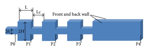
The settings of carried fluid properties: the viscosity, density, specific heat, and thermal conductivity of continuous phase are 1.003 g/m·s, 0.9982 g/cm3, 4180 J/kg·K, and 0.6 W/m·K, respectively. Density and specific heat of polystyrene microspheres are 1.055 g/cm3 and 1300 J/kg·K.
2.2. Numerical Model
2.3. Method Validation
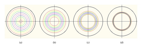
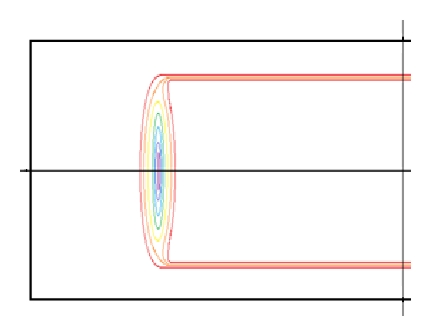
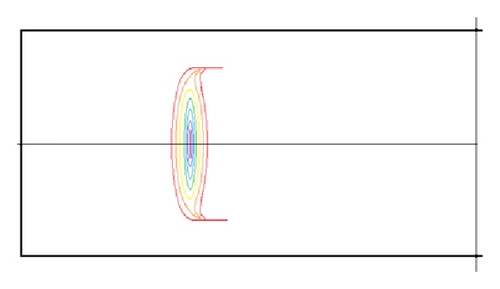
In order to verify the availability of the numerical model, we simulated numerically the flow with particles in a circular capillary. The particles distributions are shown in Figure 2. The equilibrium position is about 0.6 radius, being in good agreement with the theoretical results. We confirm the availability of our numerical model for the particle-laden microflow.
3. Results and Discussion
3.1. Particle Trapping Mechanism
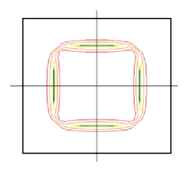
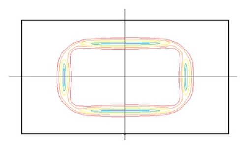
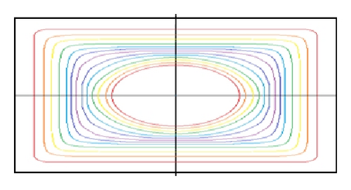
When particles are suspended in the carried fluid, the particle behavior is affected by the inertial and viscous forces occurring in the interaction with fluid. According to a number of theoretical analyses, the inertial migration phenomenon can be explained by a shear-gradient-induced lift force that causes particles to migrate away from the axis of pipe and a wall-effect-induced lift force that repels particles away from a pipe wall [22, 23]. This was proved to be right by our simulation results in Figure 2. In the case of square ducts, particles were concentrated near four walls (top, bottom, left, and right) [24]. We also simulated manifold geometries with varying aspect ratio (AR), and the results were shown in Figure 3. Numerical results show us that the particles distribution in almost in two lines when the aspect ratio is larger than 3 (see Figures 3(c) and 3(d)). This is the basis of hydrodynamic manipulation of particles in an expansion-contraction microfluidic device.
3.2. Numerical Results and Discussions
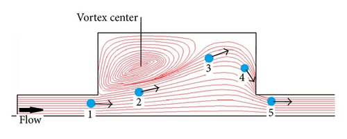
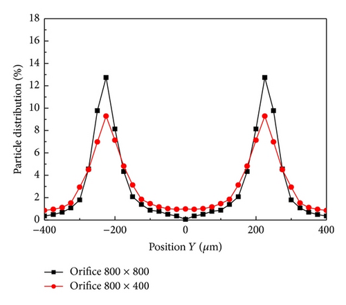
The channel geometry influences the particle trapping efficiency obviously. The main influence factors are aspect ratio, orifice number, and orifice structure. Figure 3 showed us that the aspect ratio affects the particle distribution obviously. Fortunately, the AR value of normal microfluidic device made of PDMS (polydimethylsiloxane) is bigger than 3. However, orifice number will also influence the trapping efficiency. Figure 5 shows us the contour lines of particle concentration in varying position of our device. Figure 5(a) is near the inlet but well developed, most of the particles were not trapped, and the particles distribution is almost identical over the entire section. At the end of first, second, and third orifices, the width of particle distribution decreases obviously in turn, and the particles near front and back wall fast disappeared. Near the channel end (outlet), the particles distribution appears to be two narrow lines. We also numerically simulated two orifice structures, and the comparison of their particle distributions (defined as the local population of particles to the total population of particles) was illustrated in Figure 6. Obviously the particles distribution lines in 800 × 400 μm orifice are not so narrow as those in 800 × 800 μm orifice. The reason should be that the particles trajectory will not be influenced by the microvortex in 800 × 400 μm orifice so greatly as that in 800 × 800 μm orifice. We can see in Figure 4 that the streamlines should be flat near the region from expansion to contraction when the orifice width decreased, and the particle movement at position 3 will not be so steep that the outward migration velocity is decreased.
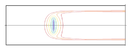
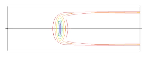
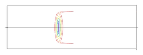
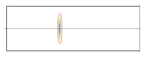
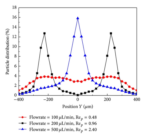
Equation (5) indicated that the flow rate is of great importance to the particle trapping. Our simulations were carried out for various flow rates ranging from 50 to 1000 μL/min, with relevant Reynolds number being about 8–160. To the particle size of 2, 7, and 15 μm, particle Reynolds numbers are calculated to be 0.02–0.41, 0.24–4.82, and 1.13–20.1, respectively. Figure 7 shows us the particle contributions in flow rates being 100, 200, and 500 μL/min, respectively, and the particle size is 7 μm. We can see that the trapping efficiency was better under the flow rate being 200 μL/min than that of 100 μL/min flow rate, and (5) indicated also that the lateral migration velocity (meaning of trapping efficiency) increased with the increasing of the flow velocity. However, almost all the particles concentrated near the center line of the channel, and the trapping efficiency closed to zero when the flow rate is very great. This can be explained as follows: when the flow velocity is great enough, the vortex center drifted right (see in Figure 4) and occupied almost the entire orifice, and therefore the streamlines in main channel will close to straight lines and the lateral migration of particles transverse to fluid streamlines decreased. In fact, Rep can express the trapping efficiency, because we know that when Rep is bigger than one, the inertial force becomes a dominant parameter for driving the lateral migration of particle transverse to fluid streamlines. In contrast, in the case of Rep less than one, the particle behavior is strongly promoted to follow the flow pattern by a viscous drag force acting on the particle surface.
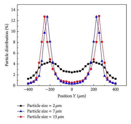
Particle size is another important factor to influence particle trapping efficiency. We simulated 3 sizes of particles 2, 7, and 15 μm, and the particle concentrations are 100, 25, and 5 × 10³/μL, respectively. In order to acquire relatively better trapping efficiency, the corresponding flow rate is 1000, 200, and 50 μL/min. The particle Reynolds numbers can be calculated using (6), and they are 0.41, 0.98, and 1.13, respectively. Although the particle Reynolds number is only 0.41 to particle size 2 μm, the flow rate is somewhat greater (1000 μL/min). The numerical results are shown in Figure 8. The particle distribution for particle sizes 7 and 15 μm showed us good trapping efficiency. Notice that the distribution center of particles with size of 7 μm is about 230 μm and that of particle with size of 15 μm is a little bigger (240 μm). However, the distribution center of particle with size of 2 μm is less than 210 μm. This result agrees with many published results. In addition, the numerical results verified once again that particle Reynolds number can predict the particle trapping efficiency.
4. Conclusions
- (1)
multiorifices structure is beneficial to particle trapping.
- (2)
Aspect ratio of square channel influences the particle distribution greatly. When aspect ratio is bigger than 3, particle distribution appears to be two-lines structure, and loop line structure for less than 2 aspect ratios.
- (3)
Particle Reynolds number is of great importance to particle trapping. When Rep is bigger than one, the inertial force is dominant and enhanced the lateral migration of particle transverse to fluid streamlines. In contrast, in the case of Rep less than one, the particle is to follow the flow pattern by a viscous drag force on the particle surface.
Conflict of Interests
The author declares that there is no conflict of interests regarding the publication of this paper.
Acknowledgment
The author acknowledges the support from the Natural Science Foundation of Zhejiang Province China (LY12A02007).


