Design of T-Shaped Micropump Based on Induced Charge Electroosmotic
Abstract
The fluid-driven efficiency of the micropump based on induced charge electroosmotic was studied by numerical simulation method. In this paper, we propose to make some improvement against the T-shaped piping design of micropump, and we embed a janus cylinder in the junction of the T-shaped pipe for the micropump design. We offer different voltage to the inlet of the pipe and carry out the numerical study of the fluid field induced by the cylinder, and the comparison of the velocity and flux of the outlet in different voltage as carried out. It is found that there are two symmetrical circulations around the polarizable side of the cylinder. And the comparison results show that the flow and the velocity of the outlet were increased with the increasing voltage of the entrance.
1. Introduction
The development of microfluidic system raises the fundamental question of how to achieve good microfluid transmission and drive results [1]. However, the phenomena of flow in microfluidic system are very different from that in the macroscopic system, which is caused by the scale effect of flow, the electric field force at the liquid/solid interface, and the coupled physics field of electric field-flow field-temperature field-ion movement field in the pipeline at the micron level [2]. The regular volume force (such as gravity and inertial force) is not generally important, and the electric field force becomes the leading driver of the liquid flow in microfluidic system. And the electroosmotic flow has become one of the most important ways of fluid transmission in the microfluidic chip, which does not require the machinery unit and provide the piston flow cross section.
However, there are some shortcomings for electroosmosi. For example, (1) strong electric field must be applied to the whole system to achieve the necessary field strength, generating Joule heating and raising the solution temperature, and temperature field will make feedback effect on electric field and flow field [3–5]. (2) Ac fields, which can reduce undesirable Faradaic reactions and Joule heating, produce zero time-averaged flow. Fortunately, these drawbacks do not apply to inducedcharge electroosmosis (Ramose et al. and Ajdari). Different from electroosmosis (EOF), ICEOF results from the interaction of the applied electric field and its own induced diffuse charge around immobile polarizable surfaces. The prototypical scenario involves a perfectly conducting ion-impermeable cylinder which is placed in an electrolyte solution. When an external electric field is applied, Faraday currents charge the region adjacent to its surface, thereby generating a polarized Debye layer. Simultaneously, the particle itself polarizes. The electric field exerts Lorentz body forces on its self-induced Debye cloud, thereby generating a velocity field [6].
In comparison with EOF, the velocity of ICEOF may be higher because of its nonlinear dependence on the applied electric field. Those unique characteristics may lead to new applications in microfluidics and nanofluidics. Recent research includes using ICEOF for mixing [7, 8] and flow regulating [9, 10] and promoting stirring and chaotic advection [11], the particles in Brownian motion [12], particle-wall interaction [13] and particle-particle interaction [14], non-spherical particles [15], and suspension dynamics [16].
In general, the induced charge electroosmosis (ICEOF) could be used for the design of micro-pump in microfluidic system. The impetus of this paper is to advance the understanding of induced charge electroosmosis (ICEOF) around a Janus cylinder in a confined T-shaped microchannel, and it is mostly concerned with the design of a super efficient T-shaped micro-pump. The relationship between fluid field and extra electric field is also studied in this research.
2. Mathematical Model and Boundary Conditions
2.1. Mathematical Model
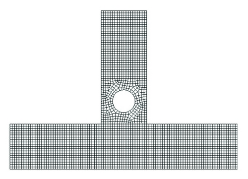
The design of the T-shaped micro-pump with a Janus cylinder is shown in Figure 1, and the black side of the cylinder is nonpolarizable and the white side is polarizable, and Figure 2 is the mesh of the computational domain.
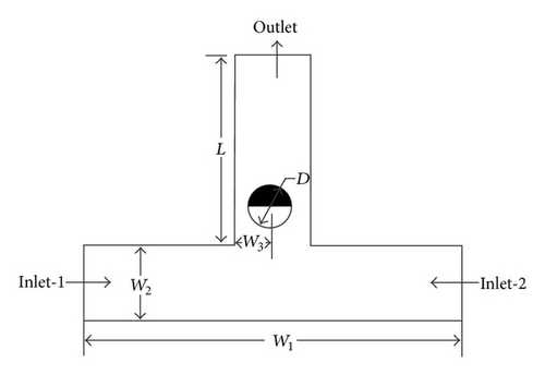
For the design of the T-shaped micro-pump, we study the ICEOF around the Janus cylinder, and the model parameters are shown in Table 1.
| Parameter | Value | Description |
|---|---|---|
| W1 | 100 μm | The distance between inlet-1 and inlet-2 |
| W2 | 20 μm | The width of the microchannel. |
| W3 | 10 μm | The distance between cylinder center and side wall. |
| L | 50 μm | The length of vertical pipe of T-shaped microchannel. |
| D | 10 μm | The diameter of the Janus cylinder. |
2.2. Boundary Conditions
For fluid flow, atmospheric pressure is specified at the inlet and outlet, and there is no slip boundary condition on the wall. For external potential, a constant value for potential is specified at the inlet and outlet, and its normal-differential value on the wall is zero. For EDL potential, its normal-differential value on the inlet and outlet is zero. Now, we will discuss the surface electric potential in detail.
We choose the control-volume-based method to solve the equations, and a specific discrete method is used to get the second-order accuracy. Firstly, we solve (7) and (4) to get the zeta potential and the external electric potential distribution in microchannel. Then, we solve (6) to get the flow field situation. In addition, in numerical situation, we should certificate the grid-independent to ensure the statistical independence of the calculations. As shown in Figure 2, the difference caused by the further mesh optimization above this number of grid is less than 1%.
2.3. Validation
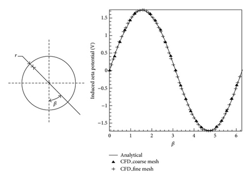
3. Results and Discussion
The present simulation assumes that the T-shaped microchannel is made of silica glass. And it is assumed that water-liquid is used as the working fluid and its physical properties are given by ε = 80, ε0 = 8.85e − 12 CV−1m−1, µ = 1.003e − 3 kgm−1s−1, ρ = 998.2 kg/m3. All the numerical solutions presented in the following have been carefully studied such that grid-independent solutions are obtained.
In this investigation, the microchannel has an external electric potential of ϕout = 0 V, while ϕin is changeable from 10 V to 50 V; accordingly, the electric field strength varies from E = 2e5 V/m to E = 1e6 V/m. The zeta potential at the microchannel wall is zero, and that of the conductive surface can be obtained from (3).
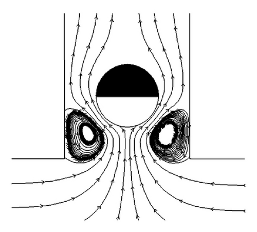
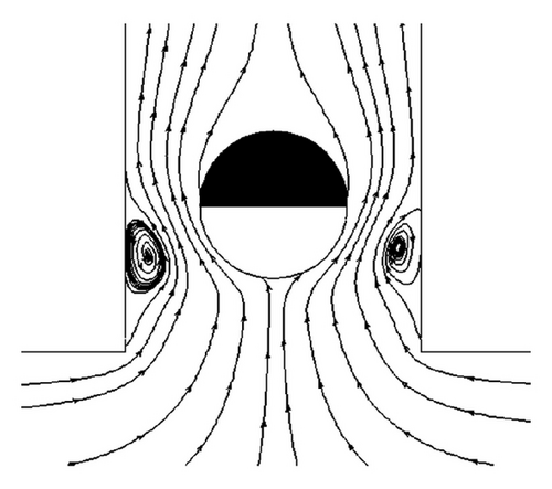
As previously stated, when the conducting cylinders are immersed in the electric field, a nonuniform distribution of zeta potential will be induced on the conducting surfaces, causing a varying driving force of the electroosmotic flow. Consequently, the slipping velocity on the conducting surfaces changes with position, resulting in a nonuniform flow field. Due to the oppositely charged surfaces, flow circulations are generated near the conductive side of the embedded cylinder.
Here, we offer the flow diagram around the Janus cylinder when E = 2e5 V/m and E = 1e6 V/m, as shown in Figures 4 and 5, respectively. We can see that consistent with the theoretical analysis, there exist 2 symmetrical flow circulations around the conductive side of the cylinder. In addition, we can find that the flow circulations will become smaller significantly and approach to the pipe wall but still be symmetrical.
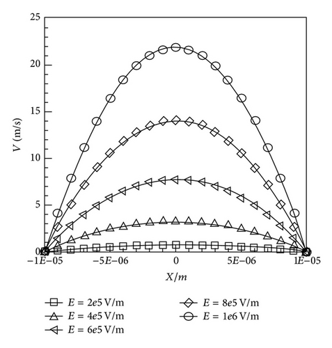
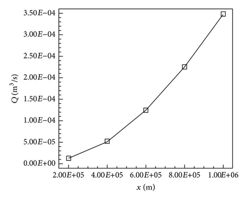
For better study of the relationship between external electric field strength and the T-shaped pump driven efficacy, we make numerical simulation when ϕin = 10 V, 20 V, 30 V, 40 V, and 50 V, respectively. As shown in Figure 6, at the outlet of the microchannel, the velocity gradient increases with the increasing of the electrical field strength, which means that the driven efficacy of the T-shaped micro-pump increases with the increasing of the electrical field. For better description of the driven efficiency, we figure out the average velocity magnitude at the outlet and offer the corresponding flux . As shown in Figure 7, we can quantitatively see that the variation range of the T-shaped micro-pump flux is from 12.41 mL/s to 348 mL/s.
In summary, the T-shaped micro pump embedded a Janus cylinder, and we propose in this paper that good fluid-driven efficiency can be obtained under small external electric potential, which is of practical value.
4. Conclusions
In this paper, we offer a design of T-shaped micro-pump that embedded a Janus cylinder. We carry out the numerical study of the fluid field induced by the cylinder and make comparison between the velocity magnitude and flux of the outlet in different voltage. It is found that there are two symmetrical flow circulations around the polarizable side of the Janus cylinder, and they can be used to improve the driven efficiency of the pump. The dependence of the driven efficiency on the electric field is also predicted. The conclusions above can be utilized for the optimization of the design of microfluidic devices.
Acknowledgments
The authors are extremely grateful to the editor and the anonymous reviewers for their constructive and valuable comments, which have contributed much to the improvement of this paper. Also, the authors gratefully acknowledge the financial support from the National Natural Science Foundation of China with Grant no. 10902105 and the Natural Science Foundation of Zhejiang Province with Grant no. Y6090406/2010R10014.


