Accelerated dual-venc 4D flow MRI with variable high-venc spatial resolution for neurovascular applications
Funding information: National Institutes of Health, Grant/Award Numbers: F30 HL137279; F30 HL140910; R01 HL149787; R21 NS106696; T32 GM815229
Click here for author-reader discussions
Abstract
Purpose
Dual-velocity encoded (dual-venc or DV) 4D flow MRI achieves wide velocity dynamic range and velocity-to-noise ratio (VNR), enabling accurate neurovascular flow characterization. To reduce scan time, we present interleaved dual-venc 4D Flow with independently prescribed, prospectively undersampled spatial resolution of the high-venc (HV) acquisition: Variable Spatial Resolution Dual Venc (VSRDV).
Methods
A prototype VSRDV sequence was developed based on a Cartesian acquisition with eight-point phase encoding, combining PEAK-GRAPPA acceleration with zero-filling in phase and partition directions for HV. The VSRDV approach was optimized by varying z, the zero-filling fraction of HV relative to low-venc, between 0%–80% in vitro (realistic neurovascular model with pulsatile flow) and in vivo (n = 10 volunteers). Antialiasing precision, mean and peak velocity quantification accuracy, and test–retest reproducibility were assessed relative to reference images with equal-resolution HV and low venc (z = 0%).
Results
In vitro results for all z demonstrated an antialiasing true positive rate at least 95% for = 2 and 5, with no linear relationship to z (p = 0.62 and 0.13, respectively). Bland–Altman analysis for z = 20%, 40%, 60%, or 80% versus z = 0% in vitro and in vivo demonstrated no bias >1% of venc in mean or peak velocity values at any . In vitro mean and peak velocity, and in vivo peak velocity, had limits of agreement within 15%.
Conclusion
VSRDV allows up to 34.8% scan time reduction compared to PEAK-GRAPPA accelerated DV 4D Flow MRI, enabling large spatial coverage and dynamic range while maintaining VNR and velocity measurement accuracy.
1 INTRODUCTION
4D flow MRI has been used to characterize the hemodynamics of neurovascular arterial and venous processes including aneurysms,1-4 atherosclerotic disease,5-7 pulsatile tinnitus,8 intracranial arteriovenous malformations,9-12 and fistulae13 among others.14-16 However, neurovascular vessels are anatomically variable and small relative to the total intracranial volume, and velocities may vary by an order of magnitude between arteries and veins.12 Thus, single-velocity encoded 4D flow does not accurately capture the full range of intracranial blood flow velocities, and conventional anti-aliasing is difficult due to small numbers of voxels within vessel cross-sections.
Dual-velocity encoded (dual-venc or DV) 4D flow MRI addresses this by acquiring interleaved low-venc (LV) and high-venc (HV) images,17 achieving wide velocity dynamic range while maintaining a high velocity-to-noise ratio (VNR).18 DV is well-suited for 4D flow measurement in neurovascular applications.6, 19-21
However, the challenge of balancing spatiotemporal resolution remains. Previous work has shown that isotropic spatial resolution of (0.8–1.0 mm)3 is needed for accurate quantification of intracranial flow22 and for advanced quantification methods including pressure estimation.23 The ability to reduce scan time by compromising temporal resolution is further limited under k-t acceleration approaches such as PEAK-GRAPPA24 and by the already decreased maximum temporal resolution of DV. Rather than reducing DV spatiotemporal resolution, an alternative method of time savings is to reduce resolution in the HV acquisition only, while preserving temporal and spatial resolution in the LV data.
This principle was applied in a five-point balanced flow encoding scheme, where the fifth flow encoding, used to correct velocity aliasing, was acquired at reduced spatial and temporal resolution and enabled a factor of 1.6 VNR gain with few aliasing artifacts.25 This approach was systematically investigated using radial PC-VIPR, which achieved a factor of 2.88 VNR gain with separately acquired, retrospectively undersampled HV used to correct LV aliasing.26 As predecessors to the current work, HV undersampling combined with elliptical k-space sampling has been previously implemented without advanced acceleration in 2D27 and 3D28 phase-contrast sequences with interleaved eight-point DV encoding, with HV undersampling accomplished by zero-filling in the phase encoding direction.
By contrast, the goal of this study was to develop and test an interleaved, three-directional DV sequence with independently prescribed LV and HV spatial resolution that preserves the dynamic range and VNR advantages of dual venc. The resulting Variable Spatial Resolution Dual Venc (VSRDV) sequence is an interleaved eight-point DV 4D Flow MRI sequence with integrated PEAK-GRAPPA acceleration and independently prescribed, prospectively undersampled spatial resolution of the HV acquisition. The hypotheses of this study are that DV scans with low-resolution HV data (with up to 80% zero-filling of HV k-space) will enable phase unwrapping of at least 95% of aliased voxels compared to a reference acquisition where the HV and LV spatial resolution is identical; and that such acquisitions will result in mean and peak velocity measurements within 15% of the corresponding values from reference acquisitions without undersampling (based on previously reported reproducibility of DV).22 These hypotheses were investigated in complex neurovascular geometries in vitro and in vivo.
2 METHODS
2.1 Pulse sequence and dual-venc velocity encoding
The prototype VSRDV sequence is based on an eight-point dual-venc 4D flow MRI acquisition scheme with Cartesian sampling, where four 3D k-spaces (phase reference and phase encoding in three orthogonal directions) are acquired in each cardiac timeframe for both LV and HV images, and a cardiac timeframe (8 × TR) defines the temporal resolution. An eight-point encoding scheme was chosen to maintain constant temporal resolution throughout the acquisition, using a previously published TE-minimizing strategy.29
The sequence incorporates acceleration using PEAK-GRAPPA, an extension of GRAPPA parallel imaging to the time domain24, 30 applied to both LV and HV. Undersampling due to PEAK-GRAPPA with = 2 and 5 is shown schematically by light gray points in Figure 1A,B, respectively. In each case, k-space outside the central autocalibration signal (ACS) region is undersampled in a “cut-corner” elliptical k-space sampling approach.31 This approach has been extensively described for both an idealized phantom and for Cartesian gradient echo sampling,32 and previously implemented in combination with GRAPPA acceleration for single-venc 4D Flow MRI in the context of neurovascular applications.5 This sampling approach preferentially zero-fills k-space positions with high-frequency information, which is most likely to be redundant with the LV acquisition.
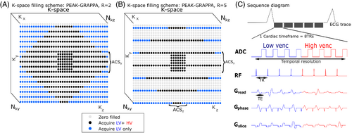
In the VSRDV sequence, variable spatial resolution of the HV acquisition was implemented by additional zero-filling at the outer corners of k-space (blue points in Figure 1A,B). As per the sequence diagram (Figure 1C), at the center of k-space a reference and three orthogonal phase encodings are collected for both LV and HV within one cardiac time frame. At the peripheral corners of k-space, two different LV k-space lines (similar to segmented k-space sampling) are acquired per flow encoding direction and cardiac time frame while the corresponding HV lines are zero-filled. This reduces the total number of heartbeats required to fill k-space but preserves the temporal resolution of the reference with equal LV and HV resolution.
2.2 In vitro experimental setup
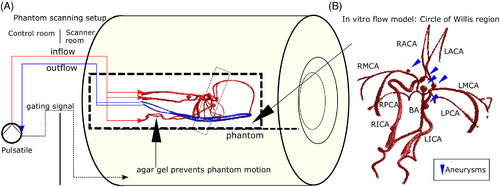
Variable Spatial Resolution Dual Venc 4D Flow MRI was tested in vitro in a realistic neurovascular anatomical replica phantom with pulsatile flow (Figure 2A,B), consisting of a silicone model of the Circle of Willis with multiple aneurysms (COW01V03: United Biologics, CA, USA) integrated into a flow circuit with a pulsatile blood pump (model 1421, Harvard Apparatus: Holliston, MA, USA). A branched arrangement of inlet tubing supplied the left and right internal carotid arteries (ICAs) and vertebral arteries (VAs) of the phantom; branched outlet tubing collected outflow from the left and right sides of the phantom. Vessels include basilar (BA); right and left internal carotid (RICA, LICA); right and left middle cerebral (RMCA, LMCA); right and left anterior cerebral (RACA, LACA); right and left posterior cerebral (RPCA, LPCA); right and left proximal posterior cerebral (RPPCA, LPPCA); right and left posterior communicating (RPCOM, LPCOM) arteries. The silicone model was suspended in 0.5% agar gel to prevent motion, maintain a realistic spatial orientation, and provide static tissue for phase offset correction. Gadobutrol (Gadavist: Bayer AG, Germany) was added to 0.2% by volume in circulating water (T1 = 100 ms, T2 = 70 ms) and 0.1% in agar gel (T1 = 200 ms, T2 = 141 ms)33 to increase signal magnitude. The flow circuit was operated with approximately 1170 ms pulse interval and stroke volume 20 ml.
2.3 In vivo cohort
Ten healthy volunteers (age 30 ± 4 y, four female) were recruited in a prospective, institutional review board-approved study. Of these, eight subjects (age 30 ± 4 y, three female) were scanned in two sessions each, 6–46 days apart, and two subjects were scanned in one session. Blood pressure was measured at each scan session to ensure the validity of test–retest reproducibility analysis.
2.4 In vitro image acquisition
In vitro imaging was performed at 1.5T (MAGNETOM Aera, Siemens Healthcare, Erlangen, Germany) with TE = 3.7 ms, TR = 6.7 ms, flip angle 15°, venclow = 55 cm/s, venchigh = 110 cm/s in all directions, and LV spatial resolution (0.8 × 0.8 × 0.8) mm3, = 160, = 30, and = 8. For each of = 2 and 5, an acquisition with z = 0 (HV resolution equal to LV) was used as a reference for aliasing identification and velocity quantification. Other tested values of z, as well as the resulting and time savings are tabulated in Table 1 according to Equation (10) above.
| Time savings versus z = 0% | |||||
|---|---|---|---|---|---|
| Reference acquisition | Experiment | Zero-filling fraction n (%) | Time (min) | Percentage | |
| = 2, scan time 21.6 min | Reference: z = 0% | 0 | 1.9 | 0 | 0 |
| Zero-Filled: z > 0% | 20 | 2.1 | 2.1 | 9.8 | |
| 40 | 2.4 | 4.2 | 19.6 | ||
| 60 | 2.6 | 6.2 | 28.6 | ||
| 80 | 2.9 | 7.5 | 34.8 | ||
| = 5, scan time 10.1 min | Reference: z = 0% | 0 | 4.1 | 0 | 0 |
| Zero-Filled: z > 0% | 20 | 4.4 | 0.8 | 8.3 | |
| 40 | 4.9 | 1.7 | 16.6 | ||
| 60 | 5.4 | 2.4 | 24.2 | ||
| 80 | 5.7 | 3.0 | 29.5 | ||
- Note: Scan time savings are calculated based on the 1020 ms pulse duration of the pump.
2.5 In vivo image acquisition
In vivo imaging was performed at 3T (MAGNETOM Prisma, Siemens Healthcare, Erlangen, Germany) with flip angle 15°, venclow = 55 cm/s, venchigh = 110 cm/s in all directions, and = 5 to keep all acquisitions within 15 minutes. LV spatial resolution was set to (1.0 × 1.0 × 1.0) mm3 (TE = 3.8 ms, TR = 6.5 ms) and decreased to (1.1 × 1.1 × 1.1) mm3 (TE = 3.7 ms, TR = 6.3 ms) if needed to accommodate subject head size in the phase encoding (left–right) direction with a consistent matrix size. Each scan session included acquisitions with z = 0%, z = 40% and z = 80% in that order, and with all other parameters, including number of cardiac time points, held constant.
2.6 Dual-venc reconstruction
2.7 In vitro image generation
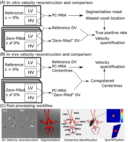
For each value of , two DV images, a “Zero-Filled DV” and a “Reference DV”, are reconstructed as in Figure 3A. The Zero-Filled DV is generated by correcting the LV from a given acquisition with the zero-filled HV data from the same acquisition (same same value of z). The same LV data as in the Zero-Filled DV are separately corrected with the HV data from the reference acquisition (same ) to generate a Reference DV dataset for each acquisition. Each pair of Zero-Filled and Reference DV datasets, therefore, has the same underlying velocity distribution of the LV, so any differences are due to varying effectiveness in antialiasing with HV. This is to enable voxel-by-voxel analysis of antialiasing effectiveness and quantification accuracy in vitro.
2.8 In vivo image generation
For each of the VSRDV acquisitions with reduced spatial resolution HV, in vivo DV images were reconstructed from the LV and DV images from the acquisition with that z value as in Figure 3B.
2.9 In vitro data analysis and statistics
Phase offset correction was performed by subtracting a first-order estimated background phase from uncorrected images, using a published method and an in-house tool.34, 35 As in Figure 3C, a manually segmented angiogram mask based on the pseudo-complex difference phase-contrast MR angiogram36 (PCMRA) was generated from the reference dataset with = 2 and applied to all datasets. In order to avoid spurious results from comparing individual voxels at the boundaries of the PCMRA-based mask, the PCMRA mask was eroded by two voxels. The antialiasing effectiveness of the HV is assessed by the true positive rate (TPR), defined as the percentage of voxels within the eroded PCMRA mask that were categorized as aliased in the Reference DV and correctly identified as aliased in the Zero-Filled DV. To assess the effect of antialiasing differences on hemodynamic quantification, mean and peak velocity measurements across multiple planes in each imaging volume were computed using a previously published semi-automated workflow, including a secondary planewise segmentation6 with the original PCMRA mask used as input. Results of Bland–Altman analysis of plane-by-plane results are visualized as Flow Distribution Network Graphs (FDNGs),22 a schematic representation of the in vitro anatomy. Relationship between z, and cross-sectional area on differences between ZF and Reference in mean and peak velocity (Δmean and Δpeak, respectively) for each plane was analyzed with analysis of variance (ANOVA). Noise is characterized for LV, HV, and DV by the ratio of the average velocity value in static tissue and venc.
2.10 In vivo data analysis and statistics
To account for subject displacement between acquisitions, a rigid registration of the PCMRA masks generated from the LV data of the Reference and Zero-Filled DV was performed as in Figure 3B using FSL FLIRT.37, 38 The resulting transformation was applied to a set of centerlines extracted from the Reference DV, which was then used to calculate cross-sectional analysis planes, perform velocity quantification and extract a resulting FDNG as in Figure 3C. For comparison, the quantification workflow was also performed without registration. An experienced operator (M.A.) reviewed each plane with the image magnitude projected on it, to exclude from analysis any planes that intersected junctions between vessels or where the automated segmentation did not match the magnitude intensity.
Bland–Altman comparison of mean and peak velocity measurements across multiple planes in each imaging volume was performed in vivo. Results for agreement with z = 0% from the same session (for all 18 sessions with z = 40% and 80%) and test–retest reproducibility between sessions (for eight subjects with two sessions each) are visualized as group-level Flow Distribution Network Graphs for each value of z (all with = 5). Relationship between z, cross-sectional area and segmentation registration on Δmean and Δpeak for each vessel and subject was analyzed with ANOVA. Test–retest reproducibility is quantified using the repeatability coefficient.39
3 RESULTS
3.1 In vitro antialiasing performance
VSRDV images were obtained of the anatomical phantom at all combinations of = 2 and 5 and z = 0%, 20%, 40%, 60%, and 80%, resulting in a maximum Rtotal of 5.7. In each case, no aliasing was visually observed in the flow regions for either HV or the Zero-Filled DV (Figure 4A).
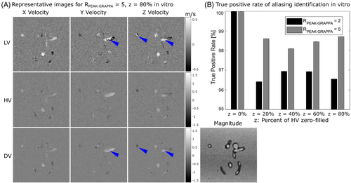
The PCMRA mask contained 52 896 velocity values, of which 625 ± 38 were found to be aliased in the LV for scans with = 2 and 565 ± 20 with = 5. For DV reconstructions at z = 0%, 571 voxels were identified as aliased in the LV for = 2 and 541 for = 5. When the HV from that acquisition was applied to the LV of other acquisitions to generate Reference DV images, the number of voxels identified as aliased increased by an average of 42 ± 38 for = 2 and 21 ± 20 for = 5. There was no relationship between z and the number of additional voxels identified as aliased (p = 0.87 for = 2 and 0.99 for = 5).
In identification of aliased voxels from the Reference DV in the Zero-Filled DV, the TPR ranged from 96.42% to 96.95% for = 2 and from 98.10% to 98.71% for = 5.40 There was no relationship between z and TPR (p = 0.21 and 0.28, respectively, for = 2 and 5).
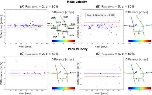
3.2 In vitro hemodynamic quantification
Mean and peak velocities were computed based on each Zero-Filled DV and its corresponding Reference DV for all segmented vessels. Mean and peak velocities through time at a single plane are shown in Supporting Information Figure S1, which is available online. For all values of Rtotal, the results of plane-wise Bland–Altman analysis for time-averaged values of each of the 13 vessels are summarized in the form of an FDNG, as shown in Figure 5A–D for the exemplary cases of z = 80% and = 2 and 5. Over all conditions tested, individual vessel mean velocity bias was 0.04 ± 0.19 cm/s and was highest (1.14 cm/s) in the RMCA at = 2 and z = 80%. Peak velocity bias was 0.09 ± 0.68 cm/s and was highest (3.32 cm/s) in the RICA at = 2 and z = 40%. None of the in vitro model's 13 vessels had statistically significant bias or offset in the Zero Filled DV relative to Reference DV in mean or peak velocity at any value. Across all 13 vessels, Bland–Altman analysis was conducted as shown in Figure 5 for the exemplary cases of z = 80% and = 2 and 5. Results for all conditions tested are tabulated in Table 2. ANOVA analysis shows no statistically significant relationship between R, z, or cross-sectional area and Δpeak. There is a significant relationship between z (p = 0.01) and cross-sectional area (6 × 10⁻⁴) and Δmean; linear modeling shows a significant difference between z = 20% and z = 80% (p = 0.002) but no other z values. The magnitude of the change in Δmean is 0.017 cm/s (0.02% of HV) per mm2.
| Mean velocity | Peak velocity | ||||||||||
|---|---|---|---|---|---|---|---|---|---|---|---|
| Z (%) | Bias (cm/s) | Bias (% venc) | Bias p-value | Limits of agreement (% mean) | Bias (cm/s) | Bias (% venc) | Bias p-value | Limits of agreement (% mean) | |||
| =2 | 20 | 0.12 | 0.11 | 0.003 | −6.8 | 8.4 | 0.07 | 0.063 | 0.521 | −6.7 | 7.0 |
| 40 | 0.06 | 0.055 | 0.108 | −6.5 | 7.2 | −0.07 | −0.063 | 0.739 | −13.3 | 13.0 | |
| 60 | 0.04 | 0.036 | 0.185 | −5.1 | 5.6 | −0.02 | −0.018 | 0.906 | −8.4 | 8.4 | |
| 80 | 0.01 | 0.0091 | 0.721 | −3.7 | 3.8 | 0.15 | 0.013 | 0.093 | −5.2 | 5.8 | |
| =5 | 20 | 0.03 | 0.027 | 0.417 | −7.3 | 7.7 | 0.08 | 0.073 | 0.765 | −16.9 | 17.2 |
| 40 | 0.04 | 0.036 | 0.349 | −7.4 | 7.9 | 0.34 | 0.31 | 0.047 | −10.1 | 11.7 | |
| 60 | 0.04 | 0.036 | 0.405 | −7.9 | 8.4 | 0.04 | 0.036 | 0.857 | −14.7 | 14.9 | |
| 80 | −0.08 | 0.072 | 0.044 | −8.0 | 6.9 | −0.13 | −0.12 | 0.230 | −7.0 | 6.4 | |
- Note: Upper and lower limits of agreement are given as a percentage of the mean reference value.
3.3 In vitro noise characteristics
As shown in Supporting Information Figure S2, LV velocity noise was 10.9% of venc at = 2 and 11.8% at = 5. DV velocity noise was 5.5% and 6.0% of venc at = 2 and 5, respectively, without significant variation with z.
3.4 In vivo hemodynamic quantification
Images with z = 0%, 40% and 80% and = 5 were acquired at all scan sessions. Mean and peak velocities were computed for all segmented vessels based on the DV at each z. Values through time at a single plane are shown in Figure 6. For all values of Rtotal the results of plane-wise Bland–Altman analysis for time-averaged values of mean and peak velocity compared to DV with z = 0% are summarized in the form of an FDNG, as shown in Figure 7. Of the 11 vessels identified in all subjects (not all subjects had RPCOM or LPCOM), bias relative to z = 0% was statistically significant for 2 vessels at z = 40% and 5 at z = 80% in mean velocity, and for 1 vessel at each of z = 40% and 80% for peak velocity. Over all conditions tested, the individual vessel mean velocity bias was 0.61 ± 0.31 cm/s and was highest (1.14 cm/s) in the RPPCA at z = 20%. Peak velocity bias was 0.54 ± 0.74 cm/s and was highest (2.1 cm/s) in the LMCA at z = 40%.
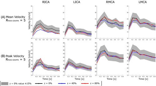
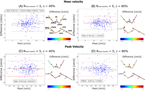
Across all 11 vessels, Bland–Altman analysis demonstrated limits of agreement of 49% and 41% for mean velocity and 26% and 24% for peak velocity at z = 40% and 80%, respectively (Figure 7). This equates to 7.22 and 6.06 cm/s for mean velocity and 11.81 and 10.74 cm/s for peak velocity at z = 40% and 80%, respectively (Table 3A,B).
| A | ||||||||||||||
|---|---|---|---|---|---|---|---|---|---|---|---|---|---|---|
| Mean velocity | Peak velocity | |||||||||||||
| z (%) | Bias (cm/s) | Bias (% venc) | Bias p-value | Offset (cm/s) | Offset p-value | LOA (%) | Bias (cm/s) | Bias (% venc) | Bias p-value | Offset (cm/s) | Offset p-value | LOA (%) | ||
| 40 | 0.53 | 0.48 | 1.00 × 10⁻⁴ | 0.09 | 0.01 | −21.03 | 28.12 | 0.74 | 0.67 | 8.2 × 10⁻⁴ | −0.02 | 0.58 | −11.48 | 14.75 |
| 80 | 0.71 | 0.65 | 1.39 × 10⁻⁹ | 0.04 | 0.24 | −15.84 | 25.48 | 0.34 | 0.31 | 0.08 | −0.05 | 0.05 | −11.17 | 12.68 |
| B | |||||||
|---|---|---|---|---|---|---|---|
| Cross-sectional area | |||||||
| z (%) | Bias (mm2) | Bias (% venc) | Bias p-value | Offset (mm2) | Offset p-value | LOA (%) | |
| 40 | 0.12 | 0.11 | 0.32 | 0.04 | 0.08 | −26.99 | 29.02 |
| 80 | −0.50 | −0.45 | 5.40 × 10⁻⁵ | −0.01 | 0.57 | −32.15 | 23.70 |
| C | ||||||||||||
|---|---|---|---|---|---|---|---|---|---|---|---|---|
| Mean velocity | Peak velocity | |||||||||||
| z (%) | Bias (cm/s) | Bias (% venc) | Bias p-value | Offset (cm/s) | Offset p-value | RPC (%) | Bias (cm/s) | Bias (% venc) | Bias p-value | Offset (cm/s) | Offset p-value | RPC (%) |
| 0 | −1.92 | −1.75 | 1.89 × 10⁻⁹ | −0.20 | 0.02 | 75.25 | −1.35 | −1.23 | 0.01 | −2.1 × 10⁻³ | 0.98 | 43.94 |
| 40 | −1.14 | −1.04 | 1.04 × 10⁻³ | −0.02 | 0.88 | 90.17 | 0.53 | 0.48 | 0.27 | 0.04 | 0.53 | 39.59 |
| 80 | −1.83 | −1.67 | 3.44 × 10⁻⁸ | −0.08 | 0.38 | 83.80 | −1.98 | −1.80 | 8.87 × 10⁻⁴ | 0.10 | 0.21 | 48.08 |
- Note: Lower and upper 95% limits of agreement (LOA) are given as a percentage of the mean reference value.
Bland–Altman analysis of area demonstrated limits of agreement of 56% and 55% at z = 40% and 80%, respectively, which equates to 6.57 and 6.56 mm2 (Supporting Information Figure S3). ANOVA demonstrates no significant relationship between Δpeak and average cross-sectional area of the vessel (p = 0.78), or z (p = 0.15) and likewise for Δmean (p = 0.35 for cross-sectional area and p = 0.28 for z).
3.5 In vivo test–retest analysis
Within the test–retest cohort, there was no significant change between sessions in either mean systolic and diastolic blood pressure (p = 0.11 and 0.60, respectively) or RR interval (p = 0.73). Across all 11 vessels, Bland–Altman analysis between the two scan sessions was conducted as in Supporting Information Figure S4 for z = 0%, 40% and 80%. Reproducibility coefficients, expressed as a percentage of the mean value at the first scan, were 75%, 90%, and 84%, respectively, for mean velocity, and 44%, 40%, and 48%, respectively, for peak velocity. These coefficients equate to 10.37, 12.25, and 10.99 cm/s, respectively, for mean velocity, and 19.38, 17.27, and 20.86 cm/s, respectively, for peak velocity (Table 3C). There is no significant relationship between registration approach and Δpeak (p = 0.38) or Δmean (p = 0.13). Test–retest RPC was higher with registration than without (by at most 11.08% of mean value for peak velocity and at most 10.38% for mean velocity).
4 DISCUSSION
4.1 In vitro: antialiasing performance and quantification
VSRDV was successfully implemented, allowing up to 35.4% reduction of scan time at a given temporal resolution for DV 4D Flow MRI. The TPR of antialiasing was greater than 95% for all values of z tested at both = 2 and 5, and had no linear relationship to z. Timecourses of individual planes demonstrated close agreement in velocity quantification, although overestimation of velocity was noted in some timepoints for Zero-Filled DV. Bland–Altman analysis of mean and peak velocity values in individual vessels demonstrated that none of the in vitro model's 13 vessels had a statistically significant bias in the Zero-Filled DV relative to Reference DV in either measurement at any value tested in vitro, and that the limits of agreement were generally within 15% of the reference value, although some individual vessels exhibited a marked difference from the Reference DV. As illustrated by FDNGs, mean velocity errors are higher in smaller vessels, which is intuitive as the area directly impacts the mean velocity calculation. Meanwhile, the highest observed error in peak velocity is noted in the RICA. This is one of the widest but most tortuous vessels in the phantom, and likely contains complex flow patterns.
4.2 In vivo: quantification and test–retest reproducibility
Timecourses of individual planes demonstrated close agreement in velocity quantification, with some timepoints showing under- or over-estimation of velocity by Zero-Filled DV, as in the RICA (with underestimation being consistent with effects of uncorrected aliasing). VSRDV with z = 40% and 80% resulted in peak velocity values within 15% of the mean value at z = 0%, and mean velocity values within 30%. Higher relative limits of agreement in the mean velocity are likely due in part to variability in segmentation: cross-sectional area could only be computed within about 30% for z = 40% or 80%. These ranges represent a difference of about 6 mm2; i.e., a matter of six to seven voxels. Because mean velocity is directly related to blood flow rate, blood flow measurements based on these data would be similarly affected. Still, limits of agreement were comparable to the retrospectively undersampled approach using PCVIPR (on the order of 17 cm/s for peak velocity in cardiac great vessels).26
Test–retest reproducibility studies suggested repeated measures of mean and peak velocity at z = 0% were likely to fall within 37% and 22% of the true value, respectively. This illustrates that agreement between z = 40% or 80% and z = 0% within the same session is comparable to agreement between repeated scans with z = 0% for both mean and peak velocity. Moreover, test–retest reproducibility did not show an apparent trend relative to z, suggesting that variability between scans is not necessarily attributable to the zero-filling approach. Additionally, the registration process that enabled a more direct comparison within scan sessions may contribute to increased variability between sessions.
4.3 Limitations and future work
This work has several important limitations. First, in an effort to narrow the parameter space to clinically relevant options, a single combination of venc values was considered with a ratio of venchigh = 110 cm/s to venclow = 55 cm/s equal to 2:1. By increasing the ratio of venchigh: venclow, in conjunction with an adjusted phase unwrapping scheme, it could be possible to further reduce noise or increase velocity dynamic range, but this possibility was not directly investigated here. This resulted in a low overall proportion of voxel values being aliased. The outlook for this work includes a systematic analysis of various ratio values. Antialiasing effectiveness in combination with other methods was also not assessed. Prior work comparing various approaches to reducing aliasing includes the comparison of dual-venc to HV,17 Laplacian to HV,41 divergence-free to Laplacian,42 and a mutual comparison43 between standard dual-venc, optimized dual-venc44 and triple-venc.45 Future work could explore the additional value of using an algorithmic,45-47 optimization-based,41, 48 or machine-learning-based49, 50 approach in combination with dual-venc.
Additionally, the Reference DV computed for comparison in this work is an imperfect ground truth estimate, which results in a paradoxical improved performance at = 5 over = 2 in vitro. There are fewer total aliased voxels in the LV at = 5 than = 2, which is consistent with increased smoothing of velocities close to venclow. Meanwhile, the inherent sampling of k-space at = 5 is less dense than at = 2, so as a result of zero-filling the outer edges of k-space the total number of ky-kz lines omitted is higher at = 2 than at = 5. HV datasets collected with and without zero-filling are more different from each other for = 2 than for = 5 as a result.
Some voxels were misclassified as aliased in the Reference DV, which occurs more often at = 2. This results in an underestimate of the TPR relative to the actual aliasing present in the LV data of the scan, so the performance identified here is a conservative estimate. Thus, when HV zero-filling is applied, the total number of identified voxels in the Zero-Filled DV is lower, but the percentage of Reference DV is higher, for = 5 than = 2. The ideal experiment to characterize contributions to data quality from PEAK-GRAPPA factor would be a comparison between = 5 and = 2, performed by undersampling the same exact data. However, as the k-space sampling pattern with = 5 cannot be obtained by retrospectively undersampling the pattern of = 2, a fully sampled dataset would have to be acquired to obtain both patterns.
In vivo data analysis was limited by the need to segment flow regions independently for each acquisition due to subject position changes. This includes the identification of the cross-sectional area, which contributes to greater uncertainty in mean velocity measurement compared to peak velocity which is relatively robust to area. One way to address this in future applications of the VSRDV sequence is to use the acquisition time savings to increase LV spatial resolution. Additionally, typical data processing with this workflow includes selection of cross-sectional analysis planes with parabolic flow profiles based on an inline visualization. In order to avoid bias in this study, plane selection for in vivo data in this experiment was done based on image magnitude, so planes may have been included in analysis for all datasets that would otherwise have been excluded in typical processing.
Finally, the sequence demonstrated here is a prototype demonstrating the variable-resolution dual-venc 4D flow MRI concept, and is subject to some limitations. This sequence is based on an eight-point encoding scheme, in order to enable straightforward calculation of phase differences for both LV and HV measurements. Seven-point encoding schemes (where the phase reference acquisition is shared between the LV and HV) are more efficient and result in a higher temporal resolution overall,17 so integration of 7TR approach with the HV undersampling approach shown here could enable additional flexibility intemporal resolution at the cost of non-uniform temporal resolution across k-space. Prior work has identified that, for neurovascular dual-venc 4D Flow MRI, temporal resolution may be reduced while maintaining good agreement in flow (although not peak velocity) values.51 This suggests that the undersampling burden could be distributed in both temporal and spatial dimensions in subsequent approaches. Given recent advances in radial and spiral 4D flow imaging52-55 and compressed sensing,56-58 it could be possible to further develop this approach through implementation of the VSRDV concept within a non-Cartesian framework. This would enable greater flexibility of both temporal and spatial resolution, with fewer constraints on the specific matrix size, and with potentially a more straightforward adaptation of the reconstruction process. Future developments can improve on the current sequence by implementing VSRDV within a seven-point encoding scheme, or exploring a view-sharing approach at the periphery of k-space in HV scans, potentially enabling further undersampling in the temporal domain.
5 CONCLUSIONS
In conclusion, the VSRDV sequence was successfully implemented, and in vitro results showed anti-aliasing error rates less than 1% and TPRs above 95% for all zero-filling percentages tested at = 2 or 5. FDNG analysis showed that no significant bias was introduced by antialiasing in any vessels in vitro. In vivo analysis at z = 40% and 80% demonstrated agreement within 15% for peak velocity compared to the reference, although increased variability was observed in mean velocity. The relative magnitude of quantification variability is comparable to prior work in cardiac imaging. Moreover, test–retest reproducibility coefficients were comparable to Bland–Altman limits of agreement between undersampled and z = 0% scans, and reproducibility coefficients were similar for z = 0%, 40%, and 80%. HV k-space could thus be zero-filled up to z = 80%, which represents up to 34.8% reduction of scan time, with acceptable impact on image quality and quantification accuracy.
VSRDV provides an opportunity to acquire dual-venc 4D Flow MRI data with maximal temporal resolution and data quality while reducing scan times. As part of a comprehensive imaging and post-processing pipeline, this may increase the feasibility of including intracranial 4D Flow imaging in the assessment of complex neurovascular disease.
ACKNOWLEDGMENTS
- NIH F30 HL140910 (Aristova)
- NIH R21 NS106696 (Rayz, Schnell)
- NIH R01 HL149787 (Markl)
- NIH T32 GM815229 (Northwestern)
- NIH F30 HL137279 (Ma)
CONFLICT OF INTEREST
Dr. Jianing Pang is an employee of Siemens Medical Solutions USA. Dr. Michael Markl receives research support from Siemens and Circle Cardiovascular Imaging.


