Higher-order surface FEM for incompressible Navier-Stokes flows on manifolds
Summary
Stationary and instationary Stokes and Navier-Stokes flows are considered on two-dimensional manifolds, ie, on curved surfaces in three dimensions. The higher-order surface FEM is used for the approximation of the geometry, velocities, pressure, and Lagrange multiplier to enforce tangential velocities. Individual element orders are employed for these various fields. Streamline-upwind stabilization is employed for flows at high Reynolds numbers. Applications are presented, which extend classical benchmark test cases from flat domains to general manifolds. Highly accurate solutions are obtained, and higher-order convergence rates are confirmed.
1 INTRODUCTION
The solution of boundary value problems on curved surfaces has many practical applications in mathematics, physics, and engineering. For example, there are transport processes on interfaces, eg, in foams, biomembranes and bubble surfaces,1-3 or structure-related phenomena such as in membranes and shells.4, 5 Herein, Stokes and incompressible Navier-Stokes flows on curved two-dimensional (2D) manifolds are considered. The governing equations for flows on moving surfaces were discussed in the works of Bothe and Prüss6 and Jankuhn et al7 based on fundamental surface continuum mechanics and conservation laws, and in the work of Koba et al,8 an energetic approach was presented. Earlier works in a similar context may be traced back to other works.9-12 For an excellent overview, the reader is referred to the work of Jankuhn et al.7 The aforementioned references often focus on mathematical properties such as the existence and uniqueness of the solutions or stability analyses. Applications are often two-phase flows where the fluid field in the bulk and on the moving interface are coupled. However, it is also worthwhile to consider the situation for fixed manifolds, eg, related to meteorology and oceanography where the flows take place on (part of) a sphere. Special geometries such as hyperbolic planes and spheres are discussed in other works.13-15
Herein, the focus is on the approximation of stationary and instationary (Navier-)Stokes flows on fixed manifolds based on the surface FEM as outlined in other works.16-18 The governing equations resemble the three-dimensional (3D) (Navier-)Stokes equations where the classical gradient and divergence operators are replaced by their tangential counterparts derived from tangential differential calculus.7 The equations are formulated in the classical stress-divergence form, contrasted to the approach in the work of Nitschke et al.19 An additional constraint is required to enforce that the velocities remain in the tangent space of the manifold; it is labeled “tangential velocity constraint.” The models are first given in strong form and are then transformed to the weak form to enable a numerical solution based on the surface FEM. Finite element spaces of different orders are employed for the approximation of the geometry and of the involved physical fields, ie, the velocities, pressure, and the Lagrange multiplier field required to enforce the tangential velocity constraint. It is found that the balance of these element orders is critical for the accuracy and conditioning of the system of equations. In particular, the well-known Babuška-Brezzi condition applies20-22 as both the incompressibility constraint and the tangential velocity constraint are enforced using Lagrange multipliers. For the case of the instationary Navier-Stokes equations, the Crank-Nicolson time-stepping scheme is employed for the semidiscrete system of equations resulting from using the surface FEM in space. Surface FEM based on linear elements was used in the recent work by Reuther and Voigt,23 where the penalty method was employed to enforce tangential velocities and a projection method rather than a monolithic approach was suggested to solve for the different physical fields. Alternatives for the surface FEM are the TraceFEM24-26 and CutFEM27, 28 where the basis functions are generated from a background mesh in the bulk surrounding the manifold of interest.
Using the FEM for the Navier-Stokes flows at large Reynolds numbers requires stabilization. Herein, the streamline-upwind Petrov-Galerkin (SUPG) approach is used.29, 30 Alternatively, other variants such as the Galerkin least-squares stabilization31 and variational multiscale approaches32, 33 may also be employed. Stabilization for advection-diffusion applications on manifolds were considered in the work of Olshanskii and Reusken.34
The numerical results show that higher-order convergence rates are achieved provided that the finite element spaces are properly chosen. In addition, the conditioning of the system of equations depends on the element orders employed for the approximation of the individual physical fields. The presented results are based on well-known benchmark test cases in two dimensions such as driven cavity flows and cylinder flows with vertex shedding, which, herein, are extended to curved surfaces. Due to the higher-order elements, the results are highly accurate and may serve as future benchmarks in the context of (Navier-)Stokes flows on manifolds. Most test cases are carried out on parametrized surfaces; however, also the situation of flows on zero isosurfaces is covered herein.
To the best of our knowledge, this is the first time where (i) general higher-order surface FEM is used for the (in)stationary (Navier-)Stokes equations on manifolds including stabilization, (ii) numerical convergence studies are presented confirming higher-order convergence rates, and (iii) benchmark test cases are proposed and solutions presented. Furthermore, the notation employed is closely related to the typical engineering literature and aims to provide a bridge from the mathematical to the engineering community.
The paper is organized as follows. In Section 2, some requirements and properties of surfaces are described and tangential differential operators are defined based on the works of Dziuk and Elliot18 and Delfour and Zolésio.35 Section 3 covers the governing equations for (i) Stokes flow, (ii) stationary, and (iii) instationary Navier-Stokes flows on 2D manifolds. They are given in strong form, weak form, and discretized weak form according to the surface FEM. Numerical results are presented in Section 4. Convergence studies are performed for a test case for which an analytic solution is available, and it is shown that higher-order convergence rates can be achieved. For the other test cases where no analytic solutions are available, it is confirmed that in the flat 2D case, well-known reference solutions are reproduced. Various meshes with different orders and resolutions have been employed to obtain highly accurate results on curved surfaces. Finally, a summary and outlook are given in Section 5.
2 PRELIMINARIES
2.1 Surfaces
The task is to solve a boundary value problem on an arbitrary surface Γ in three dimensions. Let the surface be fixed in space over time, possibly curved, sufficiently smooth, orientable, connected (so that there is only one surface), and feature a finite area. There is a unit normal vector
 on Γ. The surface may be compact, ie, without a boundary, ∂Γ=∅, see Figures 1A and 1B for examples. Otherwise, it may be bounded by ∂Γ, as shown in Figures 1C and 1D. Then, associated with ∂Γ, there is a tangential vector t∂Γ pointing in direction of ∂Γ and a conormal vector n∂Γ=nΓ×t∂Γ pointing “outwards” and being normal to ∂Γ and tangent to Γ. The surface may be given in parametrized form or implied, eg, based on the level-set method; both situations are considered herein. For the equivalence of these two cases and more mathematical details, see, eg, the work of Dziuk and Elliott.18

2.2 Surface operators
2.2.1 The tangential projector
 is defined by the normal vector as

2.2.2 Surface gradient of scalar quantities
 on the manifold is given by
 (1)
(1) is a smooth extension of u in a neighborhood
 of the manifold Γ. Of course,
 may also be some given function (rather than an arbitrary extension) in global coordinates, ie,
 . For the case of parametrized surfaces defined by the map
 and a given scalar function
 , the tangential gradient may be determined without explicitly computing an extension
 using
using
 (2)
(2) being the (3×2)-Jacobi matrix and G=JT·J being the metric tensor (first fundamental form). Equation 2 shall be used later in the context of the FEM to determine tangential gradients of shape functions. It is noteworthy that ∇Γu is in the tangent space of Γ and, thus, P·∇Γu=∇Γu and ∇Γu·nΓ=0. The components of the tangential gradient are denoted by


 is the tangential Hessian matrix. In the context of manifolds, this matrix is not symmetric,35 ie, for mixed second derivatives
 for i≠j.
2.2.3 Surface gradient of vector quantities
 are considered. The “directional gradient” of u is the tensor of tangential derivatives and defined as


 appears frequently in the modeling of physical phenomena on manifolds, ie, in the governing equations. On the other hand,
 is often used in straightforward extensions of identities such as product rules and divergence theorems. For example, we have for a scalar function f(x) and vector functions u(x), v(x)

 and
and
 , respectively. Later on, in the context of FEM implementations, it proves useful to transform covariant derivatives systematically to directional ones. This allows the computation of directional derivatives of FE (finite element) shape functions with respect to
 independent of the integration of the weak form of the governing equations.
2.2.4 Divergence operators and divergence theorem
 is given as

 , there holds

 being the second fundamental form.
3 GOVERNING EQUATIONS
In the following, we consider (i) stationary Stokes flow, (ii) stationary Navier-Stokes flow, and (iii) instationary Navier-Stokes flow on fixed manifolds. The governing equations are first given in strong and weak forms. The surface FEM is then applied for the discretization of the weak forms. As aforementioned, these models are also considered, eg, in other works6-8 among others.
3.1 Flow models in strong form
3.1.1 Stationary Stokes flow
 . The governing field equations (in stress-divergence form37) to be fulfilled ∀x∈Γ are
 (4)
(4) (5)
(5) (6)
(6) (7)
(7) (8)
(8)
 is the (constant) dynamic viscosity. It is easily shown that

 (9)
(9) and tractions
 are in the tangent space of Γ, ie,
 .
.Note that, in general, there are no explicit boundary conditions needed for the pressure p. In cases where no Neumann boundary is present, ie, ∂ΓN=∅ and ∂ΓD=∂Γ, the pressure is defined up to a constant.37, 38 This includes compact manifolds where ∂Γ=∅. In such situations, the pressure may be prescribed at a given point on Γ or it is imposed by a constraint in the form of
 .
.
Vorticity on manifolds.
 (10)
(10) (11)
(11)This scalar quantity may also be obtained using directional derivatives, ie,
 .
.
3.1.2 Stationary Navier-Stokes flow
 (12)
(12) is the (constant) fluid density with unit
 and
and
 . It is quite common to express the body force in the form ft(x)=ϱ·gt(x), where gt may consider gravity as
 for instance. The remaining Equations 5 and 6 and the boundary conditions 9 remain unchanged. The solution of the nonlinear governing equations can be obtained iteratively based on the Newton-Raphson method or other fixed-point iterations such as Picard iterations. Because the advection operator is not self-adjoint, well-known stability issues may arise for large Reynolds numbers in a numerical context.
3.1.3 Instationary Navier-Stokes flow
 (13)
(13)The functions representing the physical fields live in space (on Γ) and time, ie, in the time interval τ=[0,T]. Therefore, Equations 5-6, and 13 have to be solved in the space-time domain Γ×τ. Herein, we restrict ourselves to spatially fixed manifolds Γ.
 along ∂ΓD×τ and tractions
 along ∂ΓN×τ. Furthermore, an initial condition is needed
 (14)
(14)3.2 Flow models in weak form
 (15)
(15) (16)
(16) (17)
(17) (18)
(18) by
by

3.2.1 Stationary Stokes flow
 , body force f(x) in Γ, and traction
 on ∂ΓN, find the velocity field
 , pressure field
 , and Lagrange multiplier field
 such that for all test functions
 , there holds in Γ
 (19)
(19) (20)
(20) (21)
(21) where the curvature term vanishes due to σ·nΓ=0. Using the definition of the stress tensor, we get

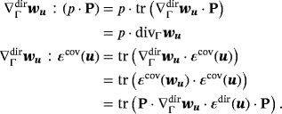 (22)
(22)It is readily verified that solutions of the strong form also fulfill the weak form in Equations 19-21. This is obvious for Equations 20 and 21 due to Equations 5 and 6, respectively. For the momentum equations, it is noted that 19 is fufilled for −divΓσ(u,p)+λ·nΓ=f. Restricting this to the tangential space by multiplication with the projector P yields the strong form of the momentum equations 4 because P·nΓ=0. It is thus also seen that the Lagrange multiplier field λ may be physically interpreted as a force in normal direction.
3.2.2 Stationary Navier-Stokes flow

3.2.3 Instationary Navier-Stokes flow
 , viscosity
 , body force ϱ·g(x,t) in Γ×τ, traction
 on ∂ΓN×τ, and initial condition u0(x) on Γ at t=0, according to 14, find the velocity field
 , pressure field
 , and Lagrange multiplier field
 such that for all test functions
 , there holds in Γ×τ
 (23)
(23) (24)
(24) (25)
(25)3.3 Surface FEM for flows on manifolds
3.3.1 Surface meshes
 (26)
(26) are classical Lagrangian shape functions of order q in reference coordinates
 and xi∈Γ are the nodal coordinates. The resulting mesh is an approximation
 of the exact surface Γ. Clearly,
 is defined parametrically through the map 26 even if the original Γ was implicitly given, eg, by the zero isosurface of a level-set function. See other works39-41 for the automatic generation of higher-order meshes on zero isosurfaces. The discrete unit normal vector is

 and
and
 are easily obtained along the element edges on the boundary of
 . The definitions of the surface operators from Section 2.2 readily extend to the case of a discrete manifold
 and are not repeated here.
3.3.2 Surface FEM
We use higher-order surface FEM as detailed, eg, in the works of Demlow16 and Dziuk and Elliott18 for the discretization of the weak forms from Section 3.2. Finite element spaces of different orders are involved. As aforementioned, suitable surface meshes of order q may be generated defining approximations
 of Γ. Let there be a “geometry mesh” of order q=kgeom with the sole purpose to approximate the geometry of the manifold
 and define the element maps 26. In particular, this mesh is not used to imply a finite element space for the approximation of the weak forms.
Next, a finite element space of order k is generated on Γh for which it is assumed that there is a second mesh of order k. The two meshes feature the same element types and number of elements with identical coordinates at the corners; however, the total number of nodes differs due to the individual orders. It is emphasized that the coordinates of the nodes in the kth order mesh are, in fact, never needed and it is only the connectivity, which is required to set up the finite element space.
 defined in a reference element with i=1,…,nk and nk being the number of nodes per element. Classical Lagrange basis functions with
 are used herein. Based on the map 26, which is completely determined by the geometry mesh, one may generate
 for all x∈Γh and tangential derivatives
 are determined based on Equation 2. This is only an isoparametric map when k=kgeom. Summing up the element contributions for nodes belonging to several elements, this generates a set of global C0-continuous basis functions
 in Γh with
 and
and
 being the number of nodes of the kth order surface mesh. Note that to generate the nodal basis
 , only the coordinates of the geometry mesh are needed; however, not from the kth order mesh. A general finite element space of order k is now defined by

 (27)
(27) (28)
(28) (29)
(29) (30)
(30)Although shape functions for the pressure and the Lagrange multiplier for enforcing the tangential velocity constraint may be discontinuous, we restrict ourselves to classical C0-continuous approximations. Note that individual orders ku, kp, and kλ are associated to the approximations of velocities uh, pressure ph, and Lagrange multiplier field λh, respectively. Analogous to the continuous case, one may impose that the functions in
 have to fulfill
 if no Neumann boundary is present.
3.3.3 Stationary Stokes flow
 , body force fh(x) in Γh, and traction
 on
on
 , find the velocity field
 , pressure field
 , and Lagrange multiplier field
 such that for all test functions
 , there holds in Γh
 (31)
(31) (32)
(32) (33)
(33) (34)
(34) =[u,v,w,p,λ]T being the sought nodal values of the velocity components, pressure, and Lagrange multiplier. For the implementation, it is interesting to compare the system 34 with the system obtained for a classical 3D Stokes problem
 (35)
(35)Assume a function, which generates K3D and G3D based on 3D FE shape functions (including classical partial derivatives with respect to x), evaluated at given integration points in 3D. The same function may be used for generating K and G provided that (i) the integration points are restricted to Γh with proper weights; (ii) the classical partial derivatives in ∇ are replaced by the tangential derivatives as in
 ; and (iii) the contribution to K at the current integration point, ie, K(xi), is projected as K(xi)=P(xi)·K3D(xi)·P(xi), which is due to Equation 22. The same shall later hold for the advection matrix
 in the Navier-Stokes equations.
As expected in the context of the Lagrange multiplier method, the matrix in Equation 34 has a saddle-point structure and is typical for a mixed FEM. The well-known Babuška-Brezzi condition20-22 must be fulfilled to obtain useful solutions for all involved fields. This may be achieved by adjusting the orders of the approximation spaces for the different fields and is further detailed in the numerical results. It is noted that stabilization may be employed to circumvent the Babuška-Brezzi condition rather than to fulfill it, see, eg, in other works,22, 42, 43 which is, however, beyond the scope of this work.
3.3.4 Stationary Navier-Stokes flow
 , viscosity
 , body force ϱ·gh(x) in Γh, and traction
 on
on
 , find the velocity field
 , pressure field
 , and Lagrange multiplier field
 such that for all test functions
 , there holds in Γh


 (36)
(36) . The distinguishing feature of K⋆ and G⋆(compared with K and G of the Stokes problem) are the added SUPG-stabilization terms. The issues related to mixed FEMs and the Babuška-Brezzi condition remain relevant.
3.3.5 Instationary Navier-Stokes flow
 , viscosity
 , body force ϱ·gh(x,t) in Γh×τ, traction
 on
on
 , and initial condition
 on Γh at t=0 according to 14, find the velocity field
 , pressure field
 , and Lagrange multiplier field
 such that for all test functions
 , there holds in Γh×τ


 . This system may be advanced in time by using finite difference schemes, and the Crank-Nicolson method is employed herein.
4 NUMERICAL RESULTS
 (37)
(37) (38)
(38) (39)
(39) (40)
(40)This can be easily extended to the case of Navier-Stokes flows where the advection term is added to the integrand in 40. Moreover, the error in the tangential velocity constraint from Equation 6 may be computed in a similar manner. The evaluation of the error ɛmom involves second-order derivatives, and convergence can only be expected for higher-order elements and sufficiently smooth solutions.
4.1 Stokes flow on an axisymmetric surface

 . In parametrized form, one may also define Γ based on the map


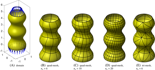

 . The upper boundary at z=L is the outflow boundary where zero tractions are applied as Neumann boundary conditions. The density and viscosity are set to ϱ=1 and μ=0.01, respectively.
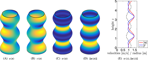
 . As the flow field is expected to be axisymmetric for this test case and the tangential velocity constraint applies, one may compute the velocity components as

See Figure 3 for a graphical representation. It is noted that the mass flow Q(z), velocity magnitude
 , and the vertical velocity component w are only functions of z, ie, they do not vary in x- and y-directions.
Finite element approximations are carried out on various meshes composed by triangular or quadrilateral Lagrange elements of different orders. For the convergence studies, meshes with nz={4,6,10,14,20,30,40,60} elements over the height are chosen; the number of elements in circumferential direction is
 . The meshes are perturbed, as illustrated in Figures 2B to 2D, to avoid perfectly axisymmetric meshes which, otherwise, could have improved the convergence rates for this special case.
The individual element orders used for the convergence studies are indicated by a four-tuple {kgeom,ku,kp,kλ}. To be precise, this tuple summarizes the employed orders for the geometry, kgeom, the velocities, ku, the pressure, kp, and the Lagrange multiplier for enforcing the tangential velocity constraint, kλ. For each tuple, meshes with different resolutions (given by nz and nθ) are considered and errors calculated, each time resulting in one curve in the convergence plots as indicated in the legends.
Systematic studies of different combinations of element orders showed that equal-order approximations for the velocity and pressure, ie, kp=ku, do not converge satisfactory (or at all), which is well known from the standard context of the incompressible Navier-Stokes equations in 2D and 3D due to the Babuška-Brezzi condition. For the studies outlined in this paper, we shall choose kp=ku−1, which is a popular choice for FEM approximations of classical incompressible flows and known as Taylor-Hood elements.46
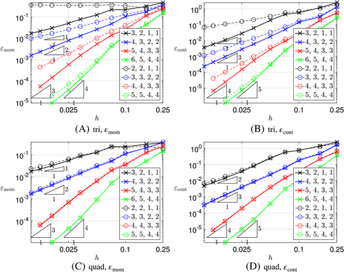
For the first study, we use 2≤ku≤5, kp=ku−1, and kλ=ku−1 which, later on, becomes the recommended standard setting. Convergence plots for ɛu and ɛp are given in Figure 4. The thick solid lines are for kgeom=ku+1. It is noteworthy that, for quadrilateral elements, setting kgeom=ku leads to almost identical results as seen from the thin dashed lines in Figures 4C and 4D. This does not necessarily hold for triangular elements; see Figures 4A and 4B where the convergence may drop by one order when setting kgeom=ku rather than kgeom=ku+1. This is later confirmed for the errors ɛmom and ɛcont in Figure 6. Therefore, we recommend to choose the geometry one order higher than ku, which is done in the remainder of this work. Another reason is that the normal vector n is present in the governing equations and is computed based on the Jacobi matrix, ie, first derivatives of the element mappings of order kgeom are involved.
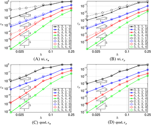
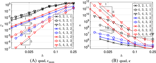
It is important to note in Figure 4 that the convergence rates in the pressure are optimal, ie, mp=kp+1; however, in the velocities one-order suboptimal, mu=ku. We have traced this back to the influence of the order kλ of the Lagrange multiplier field. This is demonstrated in Figure 5 where Figure 5A shows the error ɛu and Figure 5B the condition number κ of the corresponding system of equations (obtained with MATLAB's condest function). As aforementioned, kgeom=ku+1 and kp=ku−1. Figure 5 shows that setting kλ=1 yields convergence rates mu=2, independent of the other orders (black lines). Setting kλ=ku yields optimal convergence rates mu=ku+1 for the velocities (red lines); however, there is a dramatic influence on the conditioning, which scales with κ∼O(h−6) in this case rather than with O(h−2) for all choices where kλ<ku. Therefore, we set kλ=ku−1 in the following and accept the suboptimal convergence in the velocities.
Next, the error is observed in the strong form of the momentum and continuity equations, ie, ɛmom and ɛcont; see Equations 39 and 40. Results for kp=kλ=ku−1 are depicted in Figure 6 for triangular and quadrilateral elements. Again, the thick lines refer to kgeom=ku+1 and the thin dashed lines to kgeom=ku. As aforementioned for the L2-errors in the velocities and pressure, this makes a difference (of one order) for triangular elements, however, not for quadrilateral elements. When using kgeom=ku+1 on the safe side, the convergence rate in ɛmom is mmom=ku−1 as expected due to the presence of second-order derivatives of u in the momentum equations. The expected convergence rate in ɛcont is mcont=ku due to the presence of first-order derivatives of u in the continuity equation.
4.2 Driven cavity flows on manifolds
The stationary Navier-Stokes model is considered in this example. Starting point is the driven cavity for the case of a flat 2D domain as depicted in Figure 7A. This case has well-documented reference solutions for a variety of Reynolds numbers.47 There, a flow inside a quadratic domain Ω2D=(0,1)×(0,1) with no-slip boundary conditions on the left, right, and lower wall develops under a shear flow of u=1.0 and v=0.0 applied on the upper boundary until a stationary solution is reached. The Reynolds number is computed as Re=ϱ·u·L/μ.
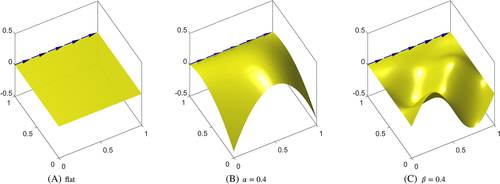


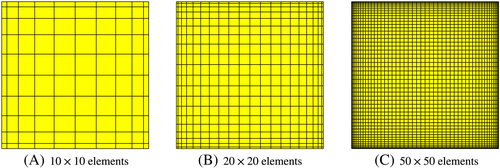
The meshes feature quadrilateral elements of different orders and are refined toward the boundaries to capture the resulting boundary layers. See Figure 9 for the meshes in Ω2D, which are mapped to 3D according to maps A and B from above for various scaling coefficients α and β. The number of elements per dimension is n={10,20,30,50,70,100}. For the numerical studies, kp=kλ=ku−1 and kgeom=ku+1 is used as recommended previously.
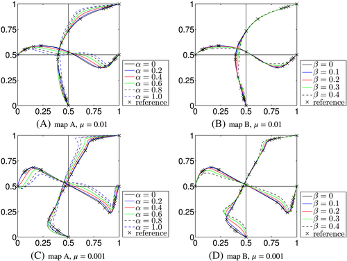
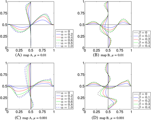
Just as for the reference solutions in the work of Ghia et al,47 the results are presented as velocity profiles along the horizontal and vertical centerlines in Ω2D. Figure 10 shows the profiles for the velocity component u along the vertical centerline and v along the horizontal centerline for the two maps with different scaling factors α and β, respectively. The crosses indicating the reference solution from the work of the aforementioned author47 are only relevant for the flat case where α=β=0. The results for the velocity component w along the two centerlines are given in Figure 11. These results have the quality of benchmark solutions and have been obtained with ku=4 and 100 elements per dimensions. The convergence of other element orders and mesh resolutions toward these profiles have been confirmed, and a small selection is shown in Figure 12. Without stabilization, the typical oscillations are seen for this rather high Reynolds number for coarse meshes with low order. As no analytical solutions for the velocities and pressure are available, it is impossible to provide convergence results in ɛu and ɛp. Furthermore, the singular pressure in the upper left and right corners lead to singularities in the derivatives of other physical fields. Thus, it cannot be expected that (optimal) convergence in ɛmom and ɛcont is achieved.

4.3 Flows on zero-level sets
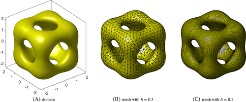
 is based on the work of Dziuk and Elliott18 and defined as

 , where gz is determined by

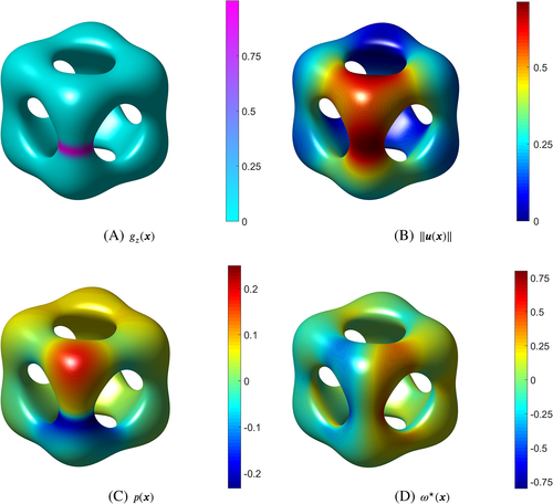
 ; C, Pressure p; D, Vorticity ω⋆ [Colour figure can be viewed at wileyonlinelibrary.com]
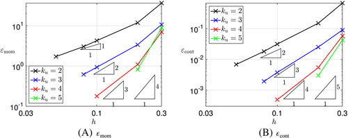
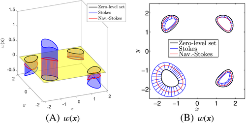
In the numerical studies, 2≤ku≤5, kp=kλ=ku−1, and kgeom=ku+1 are used. As there is no analytical solution available, convergence results are only shown in ɛmom and ɛcont in Figure 15. Higher-order rates are clearly achieved. In order to make the solution more quantitative, the velocity profiles for w(x) in the horizontal xy-plane (at z=0) are shown in Figure 16. The four closed black lines represent the intersection of the plane with the vertical “pillars” of the zero isosurface. Figure 16A shows w(x) as a third dimension, and Figure 16B shows the same result where w(x) is plotted in normal direction of the plane-pillar intersections with a scaling factor of 0.4. A clear convergence to these profiles was observed when using meshes with different resolutions and orders.
4.4 Cylinder flows
As an example for the instationary Navier-Stokes equations, the following test case is based on a channel flow around a cylinder according to the work of Schäfer and Turek.49 The geometry is first described in 2D, labeled Ω2D, and later on mapped to obtain curved surfaces in 3D. In 2D, the cylinder with a diameter of 0.1 is placed slightly unsymmetrically in y-direction of the channel in [0,2.20]×[0,0.41] (see Figure 17A). No-slip boundary conditions are applied on the upper and lower wall and on the cylinder surface. A quadratic velocity profile for u, with umax=1.5, and v=0 is applied at the inflow on the left side of the domain. At the outflow, traction-free boundary conditions are used. The density and viscosity are prescribed as ϱ=1.0 and μ=0.001. This results in a Reynolds number of Re=ϱ·um·L/μ=100 when taking the cylinder diameter as a length scale L and the average inflow velocity um=1.0 at the inflow. At this Reynolds number, periodic flow patterns known as the Kármán vortex street are observed behind the cylinder. Reference solutions are given for the lift and drag coefficients cL and cD of the cylinder49 and the current implementation confirms these numbers for the flat case (ie, in 2D or when the flat 2D domain is transformed by a rigid body motion to 3D). The reference Strouhal number St=D/(umT), with the diameter D=0.1 of the cylinder, and the time T for 2 periods of the curve of cD is given as 0.295≤St≤0.305, resulting in a frequency of about
 Hz.
Hz.

 , is defined as

 , applying some twist to the domain

 defined as


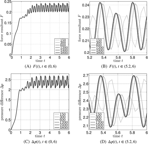
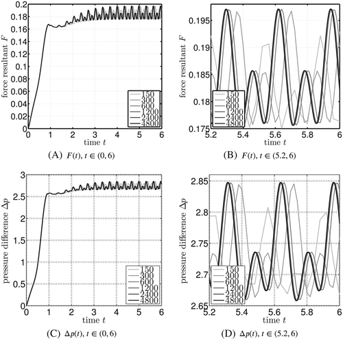
Two different meshes with 972 and 1920 elements each are used, which are refined at the no-slip boundaries to resolve the boundary layers. They are visualized for Ω2D in Figure 20 and mapped to the manifolds accordingly. We use element orders of kgeom=4, ku=3, kp=2, and kλ=2 in the numerical studies shown here. Higher orders achieved virtually indistinguishable results for the quantities shown below. It is also noted that the Crank-Nicolson method used for the time discretization is only second-order accurate. For the time discretization, nstep={150,300,600,1200,2400,4800} time steps are used. To make the results more quantitative, the stresses at the cylinder wall are summed up to obtain a force resultant
 in 3D. This is the equivalent of the lift and drag coefficients for the flat 2D case. Furthermore, the pressure difference between the front and back position of the cylinder (in Ω2D, mapped to three dimensions) is computed, ie, Δp(t)=pfront(t)−pback(t).

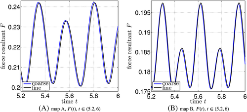
The results for map A are shown in Figure 21 for the different number of time steps. It can be seen that, after about 2 seconds, the expected vortex shedding is almost established. After 3 seconds, the resulting oscillations remain virtually unchanged. The time interval [5.2,6] is shown in more detail in Figures 21B and 21D for F(t) and Δp(t), respectively. The convergence with increasing number of time steps is clearly demonstrated. Figure 22 shows the results in the same style for map B; the same conclusions may be drawn. The spatial convergence is investigated in Figure 23 where it is found that the coarse and fine mesh employed here obtain very similar results for the chosen element orders. The frequency of the oscillations for map A is
 Hz and for map B is
 Hz; for the flat case, the frequency is
 Hz.
Hz.
5 CONCLUSIONS
The surface FEM with higher-order elements has been applied to solve Stokes and Navier-Stokes flows on (fixed) manifolds. For the governing equations, the classical gradient and divergence operators are replaced by their tangential counterparts. An additional constraint is needed to ensure that the velocities are in the tangent space of the manifold. Stabilization is required for the case of Navier-Stokes flows at large Reynolds numbers, and the standard SUPG approach is used herein.
For the discretization, the surface FEM is employed with quadrilateral or triangular elements. Element spaces of different orders are used for (i) the geometric approximation of the manifold, ie, kgeom; (ii) the approximation of the velocity fields, ie, ku; (iii) the pressure field, ie, kp; and (iv) the Lagrange multiplier field for the enforcement of the tangential velocity constraint, ie, kλ. The choice of these orders affects the properties of the resulting FEM in terms of conditioning, accuracy, and stability. Particularly useful combinations for a chosen order ku are kgeom=ku+1 and kp=kλ=ku−1. Some benchmark test cases for flows on manifolds are proposed and higher-order convergence rates are achieved. The notation used in this work is closely related to the engineering literature for the FEM in fluid mechanics. Implementational matters are outlined.
There is a large potential for future research related to this work. One may investigate different stabilization methods such as Galerkin least-squares stabilization and variational multiscale methods. Stabilization may also be useful to circumvent the Babuška-Brezzi condition and enable equal-order shape functions for the velocities and pressure. The tangential velocity constraint may be more efficiently enforced based on penalty methods or other Lagrange multiplier approaches such as the Uzawa method. We believe that flows on manifolds have a strong potential for fundamental research in mathematics, physics, and engineering.
ACKNOWLEDGEMENT
The fruitful discussions with Dr Sven Groß, Dr Thomas Rüberg, and Prof Günther Of are gratefully acknowledged.


 . For tangential tensor functions with A=P·A·P, the term involving the curvature ϰ vanishes because then A·nΓ=0. In this case, we also have
 .
.