Rechargeable Aluminum-Air Batteries Based on Aqueous Solid-State Electrolytes
Abstract
The feasibility to recharge aluminum-air cells realized with a dual water-based electrolyte without separator is demonstrated. The dual electrolyte, made of polyvinyl alcohol and Xanthan gum, has a different water content, lower at the anodic interface, where parasitic reactions involving hydrogen production play a crucial role in hindering metal re-deposition, and higher at the cathode side, where water, depending on the pH, allows an efficient reduction of oxygen during discharge or the oxygen evolution during cell charging. The galvanostatic cycles show in the first discharge and charge cycles, the characteristic plateau trends of secondary batteries. By electrochemical impedance spectroscopy analysis effected after each discharge/charge phase and by measuring anode and cathode potentials during cycling, it is demonstrated that, during the first cycles, the re-deposition of aluminum is possible by adopting adequate water management in the electrolyte, while the cell malfunctioning in the subsequent cycles is mainly due to the damage of the cathode.
1 Introduction
Due to the increase in renewable energy sources and the “green” transformations imposed by current legislation, the demand for new batteries is on the rise.[ 1 ] Presently, lithium battery technology dominates the market and, although large companies are still pushing this technology, the most mature to guarantee short-term results, various issues related to the procurement of raw materials, safety, disposal, and recycling of waste have led to new research fields to develop devices based on new electrochemical concepts[ 2 ] and to identify new materials to be used in storage devices that are safer and more environmentally friendly.[ 3 ] In this context, metal-air batteries constitute one of the most promising electrical energy storage devices.[ 4 ] In fact, the functioning of a metal-air battery is based on a redox reaction between a metal anode (typically Zn, Ca, Al, and Fe, in addition to Li) and a catalyzed cathode with an open structure that allows the reaction with oxygen in the atmosphere. These metals release more than one electron in the redox reaction, and this determines high theoretical capacity and high energy density when used in batteries in combination with suitable cathodes.[ 5 ] The metal-air batteries, as long as electrolytes and catalysts based on environmentally friendly materials are used, are the intrinsically safest and the most sustainable energy conversion devices, especially when solid electrolytes are employed.[ 6 ]
Among the various metals considered as anode in metal-air batteries, aluminum is the material that has the most satisfactory parameters of economy/ecology and electrochemistry at the same time.[ 7 ] Valuable characteristics of aluminum are metal lightness, formation of trivalent ions in the redox reactions, which implies high theoretical volumetric and gravimetric capacities of the devices (four times compared to Li and 77% of Li, respectively), abundance in the earth's crust, low cost, and recyclability.
In contrast, although water on anodes in metal-air batteries is detrimental, it is useful and necessary on cathodes because it allows efficient oxygen cathodic reactions, both in discharge (oxygen reduction reaction (ORR)) and during charging (oxygen evolution reaction (OER)),[ 8 ] and facilitates the ion diffusion toward catalytic sites.
The only data reported in the literature on rechargeable batteries using aluminum as anode refer to devices made with nonaqueous electrolytes,[ 9 ] whose eco-toxicity is not yet fully known.[ 10 ] In addition, cycling stability and energy density are still unsatisfactory for their large-scale development.[ 11, 12 ] Furthermore, the use of organic (non-aqueous) electrolytes poses problems of eco-sustainability related to the costs of production, safe use, disposal, and recycling.
The technological challenge in research on aluminum-air batteries, therefore, consists not only in obtaining “practical” values of energy and power density that are competitive with those of current lithium-ion systems but also in making these systems electrically rechargeable, possibly using sustainable materials in cathodes and water-based electrolytes, by adopting adequate strategies to protect the metal anode and allow the re-deposition of the metal.[ 13 ]
In the present paper, we demonstrate that aluminum-air cells made with such water-based polymer electrolyte configuration can be electrically recharged. The cell cycles have shown that the electrolytes thus conceived allow the aluminum-air batteries to be recharged in the first cycles, while the instability of the cycle is mainly due to the increased cathode malfunction during prolonged cycling.
2 Results
The three-electrode cyclic voltammetry (CV) of PVAHCl electrolyte and those of dual PVAHCl/XaKCl electrolyte (hereafter DE, see Section 4 for preparation details of the PVA based acidic PVAHCl and Xanthan based saline XaKCl electrolytes) were reported in a previous study.[ 14 ] The electrochemical windows were wide 2.2 V, being the voltammograms almost flat from −0.8 V to +1.4 V (vs SHE) with current densities lower than 10 μA cm−2, also in a humidified dual electrolyte. At the value of the aluminum standard reduction potential, namely −1.66 V, the reduction current densities were lower than 40 μA cm−2. These findings suggested the possibility to use these electrolytes in rechargeable aluminum-air batteries. In the same paper, we showed that constant humidification of the DE during cell functioning allowed the cell capacity to be increased by about one order of magnitude.
A crucial role in the realization of secondary aluminum-air cells based on the combined use of these water-based electrolytes is played by the anolyte, which in addition to having a reduced water content, must also be able to support the electrochemical reversibility of the Al/Al3+ couple. We tested the electrochemical reversibility of the Al/Al3+ couple in the anolyte through CV measurements on Al|PVAHCl|Al and Pt|PVAHCl|Pt symmetrical cells, as reported in Figure 1 .
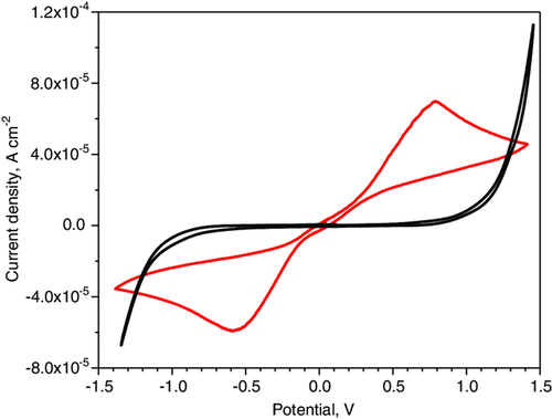
The shape of non-blocking cell voltammogramm is similar to that recorded for other symmetrical cells assembled with polymer electrolytes that show reversibility of redox couples, such as Li/Li+ or Mg/Mg2+.[ 25, 26 ] The observed anodic and cathodic current peaks in non-blocking symmetrical cells are higher than the currents detected in blocking cells, confirming the electrochemical reversibility of the Al/Al3+ couple in this electrolyte and therefore, in principle, its suitability in secondary batteries. However, it must be taken into account that the anolyte material is porous, it tends to lose solvent especially if used in open supports, such as those of metal-air cells, and this alters conductivity even during cell operation. Therefore, their possible use, also in secondary batteries, requires the stabilization of its water content in some way, for example, by using constant external humidification.
In Figure 2 , we report a typical discharge test at 200 μA cm−2 of the cells realized with DE effected with improved humidification, with respect to the cell assembled for electrochemical studies presented in a previous study.[ 14 ]
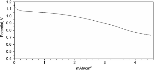
The cell potential maintains values above 1 V for 10 h. The cells can be discharged at higher currents with an increase in external humidification.
Figure 3 shows a galvanostatic cycling effected on a DE cell with the same humidification conditions used for tests of Figure 2.
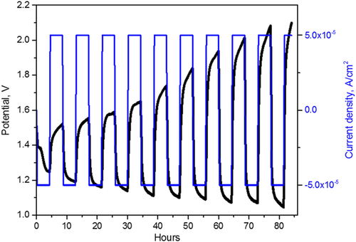
The open circuit voltage of the fresh cell was 1.47 V. The cell was discharged and charged at current densities of 50 μA cm−2. The charging and discharging durations were 4 h. As it results from Figure 3, the charging potential of the first four cycles varies slowly between 1.52 and 1.62 V. The charge phase of the third cycle clearly shows a plateau throughout its duration as some rechargeable batteries.[ 27, 28 ] After the fourth cycle, this potential increases faster and is higher than 2 V already in the eighth cycle. Instead, the discharging potential decreases during all the cycles.
The potential variations may be attributed to the increase of both electrode interface and electrolyte resistances. The interface electrode resistance on the anode is affected by oxide formation, while the electrolyte resistance is regulated by the water content, consumed during cell functioning, and partially compensated by the poor external supply. In contrast, an increase in the external water supply could cause anode flooding and impede aluminum reduction during charging. To understand these phenomena, we performed potentiostatic electrochemical impedance spectroscopy (EIS) analysis after the rest of each discharge and charge phase.
In Figure 4 , the Nyquist plot of the fresh cell is reported. An equivalent circuit describing the DE cell is reported in Figure 5 .
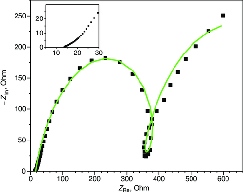
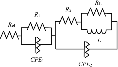
In Figure 5, R el, R 1, and R 2 describe electrolyte resistance and charge transfer resistance at anode and cathode, respectively. The CPE elements are the constant phase elements and describe the double-layer capacity of the electrode interfaces.[ 29 ] The impedance R L|L describes inductive loops at low frequencies, as observed in many systems and generated by physical processes involving ion movement on the surfaces[ 30-32 ] or connected to the water transport in the membrane, as observed in some studies in fuel cells.[ 33 ]
The circuit element values fitting the Nyquist plots in Figure 5 are reported in Table S1, Supporting Information, first line.
The conductivity of the electrolyte of the cell used in the test of Figure 3 was 3.3 × 10⁻² S cm−1.
Figure 6 shows the Nyquist plots acquired after each discharge and charge phase during the cycle reported in Figure 3.
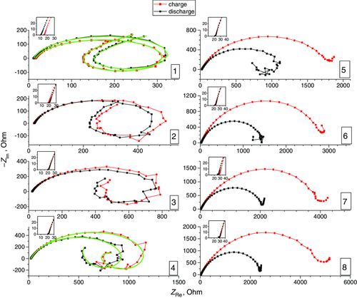
The equivalent circuit which describes the DE cell after the discharge/charge cycles up to the fourth cycle is shown in Figure 5. The values found in the fitting of some Nyquist plots (first and fourth cycles) in Figure 6 are reported in Table S1, Supporting Information. As displayed in the figure insets, the electrolyte resistances vary between 10 and 30 Ω so that the conductivity values vary between 3 and 1.5 × 10⁻² S cm−1 throughout the test duration. In particular, from the second to the fifth cycle, the electrolyte resistance is almost constant at 20 Ω after both charging and discharging, then it slowly increases to 30 Ω, suggesting that the modest external water supply to the membrane does not increase the wetting of the anode during the duration of the cycle. A substantial overlap of the Nyquist plots acquired after charging and discharging phases is observed during the first cycles, when slow increasing or plateau-like trends are observed in charging curves. As shown in Figure 6, the inductive contribution to the impedance at low frequencies is relevant up to the fourth cycle. The adsorption phenomena described by R L|L are facilitated by the forced humidification of the cathode, which decreases when the XaKCl catholyte hardens and is no longer able to be wet after a prolonged cell operation. After the fourth cycle, the low-frequency inductive loop disappears and the equivalent circuit in Figure 5 does not correctly describe the electrochemical system. From Figure 6, it results that, when the inductive loop disappears from the fifth cycle onward, the amplitude of the semicircle in the Nyquist plots varies in the successive cycles of charge–discharge, with the amplitude after the charge greater than that of the subsequent discharge. The variation of the semicircle amplitudes due to charge transfer resistance. If the charge is no longer efficient, the electrons are not neutralized by any cation and accumulate at the anode, then this excess of electrons on the anode increases the resistance to Al anode oxidation and consequently to the cathode ORR during the EIS tests. In the successive discharge, the excess electrons are eliminated and the Nyquist plot measures a lower resistance to anode oxidation. This behavior of the EIS is confirmed by the values of the anodic potentials during cell cycling.
To measure the electrode potentials during cell cycling, the potential of the cathode was separated by using a reference electrode (Ag/AgCl, saturated KCl). In Figure 7 , the cell potential as well as the cathode and anode potentials versus SHE during galvanostatic cycles are reported. The cycle was effected in the same conditions of Figure 3.
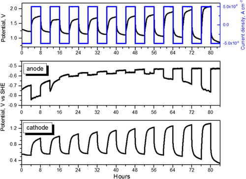
From Figure 7, in the first seven cycles, the cell discharge potential varies between 1.2 and 1 V, and charging potentials are lower than 1.74 V. Correspondingly, the cathodic discharge potentials maintain constant values. This indicates that the cathode, best suited for ORR reactions, is still functioning well during these cycles. Hence, in the first seven cycles, the reversible electrochemical reactions are more efficient.
The anode potential during the discharge phases varies between −0.75 and −0.65 V during the first two cycles due to activation phenomena, and stabilizes from −0.58 to −0.52 V after the second cycle. The almost constant value of the anode discharge potential indicates that the anode metal surface is not totally consumed or oxidized, and is still capable of releasing electrons in the electrochemical reaction at a constant rate. During the charging, the anode potential is comprised between −0.83 and −0.63 V during the first two cycles and then between −0.6 V and −0.56 V in the successive four cycles. The close values of anodic potentials during charge/discharge phases suggest that charge/discharge reactions occur at comparable rates. The almost constant charging potential values indicate that the electrons sent to the anode are neutralized by the cations arriving from the cathode, presumably, Al3+ deriving from Al(OH)3 decomposition (reactions 3). In fact, as the electrolyte resistance is unchanged, the water content in the electrolyte does not provoke flooding or excessive humidification at the anodic interface, and therefore the water reduction on the anode is not the main reaction responsible for potentials observed during these cycles. After the sixth cycle, the anodic potential during the charge becomes more negative, suggesting a minor neutralization of electrons due to a minor aluminum re-deposition on a metal anode or increased surface passivation after 50 h of functioning.
From Figure 7, lower plot, the cathode discharge potential is constant during the first six discharges, after which it decreases, while the charging potential increases during all cycles, but remains below 1 V until the sixth cycle. From the seventh cycle onward, the charging potential exceeds 1 V. The increase in the charging potentials indicates inefficient OH− oxidation, reversal of the second equation (Equation (5)), with consequent lower electron production. This is due to the not optimal behavior of cathodic catalyst for OER, as expected for a Pt-based catalyst. A depletion of the OER implies a minor Al3+ release from the direct reaction products (reaction 5), with consequent minor Al re-deposition on the anodic surface and more negative anodic potential in the galvanostatic cycle. These correlated trends between anode and cathode potentials confirm that the observed changes are due to an electrochemical reaction and not to parasite chemical reactions. During the charging, the Pt–C cathode structure could be mechanically broken by oxygen produced and trying to escape from the electrode[ 34 ] and the catalyst may be deactivated.[ 35 ] Then, it is expected that the Pt–C electrode may drop in performance when used in successive discharge modes. In addition, the cathodic reaction is strongly influenced also by the water content in the electrolyte, which is altered during cell operation. The malfunctioning of the cathode is clear from the seventh cycle onward, when its discharge potential decreases. Therefore, the subsequent charges, and the entire functioning of the cell, are permanently compromised due to the malfunction of the cathode.
Finally, to test the effect of the solid membrane on the DE cell behavior and specifically on the anodic potential, we performed the same cycle of Figure 7, but assembled with the sole XaKCl electrolyte, without membrane. The results of the test are reported in Figure 8 .

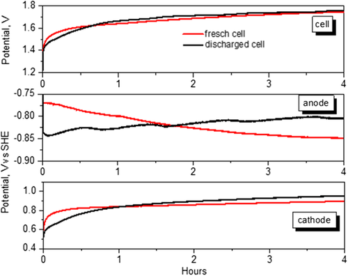
As it can be observed from Figure 8, anodic and cathodic potentials appear decoupled and while the potentials of the cathode, in both charge and discharge phases, are similar as the cell assembled with DE, the potentials of the anode are different in charging. Notably, the charging anodic potentials are 1 V more negative than that of discharge potentials, and they are constant for the duration of the charge phases. The negative potentials indicate that the electrons accumulate at the anode because they are not neutralized by any cations, due to Al passivation occurring when neutral aqueous electrolytes are contacted with the metal. Then, the membrane, avoiding contact with water, controls the passivation of the anode and allows more efficient electrochemical reactions. In contrast, if a contribution to the charge potentials in Figure 7 was due to the reduction of the water present on the anode, this should be evident also on the charging potentials performed on a cell not previously discharged. Figure 9 shows the cell potential, anode and cathode potential versus SHE during the charging carried out on a DE cell that was not previously discharged. For comparison, in the same figure, the same potentials are shown for a DE cell discharged for 4 h at 50 μA (charge curve of the first cycle of Figure 7). The trends are very different, in particular, the anodic charging potential of the not-discharged cell is initially less negative and shifts toward more negative values.
3 Conclusions
We have reported evidence that aluminum-air cells can be recharged using fully water-based electrolytes, without the use of organic or nonaqueous solvents, as long as different water content is achieved between cathode and anode. For this purpose, we have assembled cells in which the anode and cathode are separated by two different electrolytes, made with water content lower on the anode side. The cells were discharged at 200 μA cm−2 with a voltage higher than 1 V for 10 h. The CV of the anolyte tested on non-blocking Al symmetrical cells showed the reversibility of the Al/Al3+ couple. The galvanostatic cycle, carried out with ±50 μA cm−2 for 4 h in charge and discharge, showed reduced overpotentials in charge for the first cycles, after which they increased faster up to exceed 2 V in the eighth cycle.
EIS analysis performed after each charging and discharging phase shows that the electrolyte resistance remains almost unchanged or is a bit increased during the test, suggesting that a modest external water supply is not able to alter the water content in the whole electrolyte, and therefore at the anode interface. However, the charge transfer resistances are increased after charge from the fifth cycle onward, presumably due to a damage of the cathode or a reduction of water amount at the cathode interface, as the catholyte was more critically dried with respect to the anolyte.
The three-electrode cycles showed that, after the first two cycles, the anodic potential in the next four cycles is constant during the charging and variations of anode potentials in charge and discharge are very close, within a difference of only 50 mV, suggesting reversible aluminum stripping/deposition. During the successive cycles, the charge potential increases to more negative values, indicating a less efficient aluminum deposition, while the discharge potentials stabilize around constant values.
The cathode discharge potentials are quite stable during the first six cycles, after that the variation of the cathode potential, both in discharge and in charge, is more significant. The increase of the cathode charge potential toward more positive values, correlated with the anode potential behavior, indicates the involvement of an electrochemical reaction also during recharging, reasonably associated with aluminum re-depositions.
Better cycling stability is expected by using more suitable catholytes and more efficient catalysts.
4 Experimental Section
We prepared two different gel polymer electrolytes with different water contents and used them as anolyte and catholyte. The preparation of the electrolytes was extensively described in previous studies.[ 8, 14 ] Briefly, the anolyte was prepared by mixing PVA (Mowiol 10-98,Mw ≈61 000 Sigma-Aldrich) to 5 m HCl solution at a ratio of 150 mg mL−1. The PVA and liquid solution were stirred at 60 °C until PVA dissolution. After cooling, 30 mL of the obtained solution was casted on a 70 mm diameter Petri dish and left to rest for 10–15 days at room temperature. The formed electrolyte, hereafter PVAHCl, had the shape of a flexible yellowish membrane, 0.7–1 mm thick (Figure S1, Supporting Information). After the membranes were removed from the Petri dish, they were stored in airtight containers to avoid overdrying, which affected mainly the ionic conductivity. In fact, depending on the drying duration, the membranes exhibited ionic conductivity in the range of 0.07–2.2 × 10⁻² S cm−1.[ 14 ] A water percentage in the membranes was estimated to be about 8 wt%. Also, the membranes were very stable over time and quite resistant to bending and torsion. They remained flexible even when left to dry for many days and, if left in water, they became softer, but absolutely did not dissolve in water or break, even after many days of immersion. The membranes were porous. In fact, we evaluated that 13 × 13 mm2 pieces of membrane uptook water up to 50% of their weight after 48 h’ immersion in distilled water, as well as they lost all the accumulated water after being left in the air at 20 °C for 5 h. The porosity of membranes was determined to be around 40%.
The catholytes were saline Xanthan-based hydrogels.[ 8 ] The saline hydrogels were prepared by mixing and kneading Xanthan powders (powders from Xanthomonas campestris, Sigma-Aldrich) in KCl saturated solution at a ratio of 700 mg mL−1 at room temperature. The resulting electrolyte, hereafter XaKCl, was a soft and slightly gluey hydrogel with a water percentage of 60 wt% (Figure S2, Supporting Information).
Both the electrolytes can be handled with bare hands without experiencing excessive discomfort, such as burning or tingling on the skin.
The anodes were made of ultrapure aluminum (Puratronic, 0.5 mm thick, 99.998%, Alfa Aesar) in the form of 13 mm disks.
The cathodes were made of a Pt/active carbon catalyst (10 wt% Pt, provided by Aldrich in powder form) suspended in solvent (1-methyl-2-pyrrolidinone, Aldrich) with a binder polyvinylidene fluoride (Aldrich, powder form) in the ratio of 10:1. The suspension with catalyst, prepared with 1 cm3 of solvent per 220 mg of solid mixture, was pasted on carbon cloth (H2 Planet). After drying, the final Pt concentration was 2.5 wt%, referred to as the whole cathode.
The cells were assembled by contacting the anode, anolyte, catholyte, and cathode without separators and squeezing all components in an open holder. The catholyte used in the cell was 80 mg and, when squeezed between anolyte and cathode, it was about 0.4 mm thick and its surface slightly exceeded that of the cathode. To ensure long-term humidification of the electrolytes, a thin strip of about 0.2 cm−2 of commercial A4 paper was inserted between the cathode and the catholyte, keeping one end wet in distilled water (Figure S3, Supporting Information, and a previous study).[ 14 ] When the cell was disassembled after prolonged functioning, the PVAHCl anolyte was still flexible and slightly gluey at the anode side (Figure S4, Supporting Information), while it was unchanged from the cathode side. Instead, the XaKCl catholyte was severely modified and resulted in a dry, thin, and brittle piece of material. The cell weight was approximately 0.5 g with about half of the weight due to the 0.5 mm thick anode.
The CV was performed on two electrode symmetrical cells at 1 mV s−1 scan rate and across the voltage range from +1.5 to −1.5 V. The EIS and galvanostatic discharge and cycling tests were performed by Zahner Zennium and Autolab PGSTAT302N electrochemical workstations. The EIS spectra were acquired in the potentiostatic mode with the applied frequency varied between 2 MHz and 10 mHz and the potential amplitude equal to 10 mV.
Acknowledgements
We acknowledge the Open Access Funding provided by Consiglio Nazionale delle Ricerche within the CRUI-CARE Agreement.
Open Access Funding provided by Consiglio Nazionale delle Ricerche within the CRUI-CARE Agreement.
Conflict of Interest
The authors declare no conflict of interest.
Open Research
Data Availability Statement
The data that support the findings of this study are available from the corresponding author upon reasonable request.


