Oxygen-Carrier Development of Calcium Manganite–Based Materials with Perovskite Structure for Chemical-Looping Combustion of Methane
Abstract
The present work is related to the upscaling of calcium manganite–based oxygen-carrier materials, which have a perovskite structure, both with respect to the use of inexpensive raw materials, i.e., instead of pure chemicals, and the upscaling of production to multitonne batches. Results are presented from the two different stages of material development, i.e., raw material selection and upscaling. The evaluation involves both operation in chemical-looping combustor units of 300 W and 10 kW, and material characterization. In the latter unit, the gas velocities in the riser and in the grid-jet zone of the gas distributor come close to gas velocities of industrial-scale units and, therefore, this unit is also used to assess particle lifetime. Results from the various chemical-looping combustion units and oxygen-carrier materials produced from various raw materials of both high and low purity show that very high degrees of fuel conversion can be reached while achieving very high oxygen-carrier lifetimes. The composition of the oxygen-carrier materials seems robust and flexible with respect to the precursors used in its manufacturing.
1 Introduction
Chemical-looping combustion (CLC) of gaseous fuels could be of interest in industrial processes for heat, power, or hydrogen production with carbon capture. For instance, production of steam and hydrogen from refinery gas are possible applications. A key for a successful CLC process is the oxygen carrier, which transfers the oxygen from the air to the fuel, thus preventing the mixing of combustion air with the combustion products, i.e., CO2 and H2O, and providing a possibility to capture carbon dioxide without the need of costly and energy-consuming gas separation. The oxygen carrier must provide high conversion. Therefore, early work focused on nickel oxides, which have the highest performance of monometallic oxide systems, albeit being relatively expensive and having issues from a health, safety, and environment perspective. Eventually, combined oxides with good performance were found such as calcium manganite (CaMnO3), which has a perovskite structure. The main advantage with this type of oxygen-carrier material is the ability to release oxygen to the gas phase, thus promoting fuel conversion in the fuel reactor (FR). A significant number of such oxygen-carrier materials were produced and tested. It was found that a perovskite structure can be obtained relatively easy with widely different raw materials for calcium (Ca), manganese (Mn), titanium (Ti), and magnesium (Mg). The oxygen-carrier materials produced generally had high reactivities and high attrition resistances but were prone to sulfur poisoning. A current review of development of oxygen-carrier material research was published by Lyngfelt et al.1
1.1 Chemical-Looping Combustion
CLC is an innovative method to oxidize fuels with inherent separation of CO2. The most common adaptation of CLC is based on two interconnected, fluidized-bed reactors: in the air reactor (AR) air is used to oxidize a solid oxygen carrier, and in the FR fuel is added and oxidized by the oxygen carrier, which, in turn, is reduced. In this way the combustion products are not diluted with nitrogen and, after condensation of steam, the FR flue gas ideally consists of pure CO2. In contrast to other carbon capture technologies, such as absorption or adsorption of CO2 or oxyfuel combustion, there is no direct energy penalty for gas separation associated with CLC. General information about chemical looping and an overview of trends and developments can be found elsewhere.1-3
Suitable process temperatures vary slightly for different oxygen-carrier materials, but are usually considered to be within the range of 800–1050 °C. The most commonly proposed way to design a chemical-looping combustor is to use circulating fluidized beds (CFBs) with oxygen-carrier particles as bed material instead of an inert bed material, usually silica sand, used in conventional applications. Commonly proposed oxygen-carrier materials include transition monometallic oxides such as nickel, iron, copper, or manganese oxides (NiO, CuO, Fe2O3, or Mn3O4) with or without inert support materials such as alumina (Al2O3) or zirconia (ZrO2).4 Later work has investigated a number of combined oxides, e.g., ilmenite (FeTiO3) and a number of combined manganese oxides, where Mn is combined with Fe, Mg, Si, and Ca.5 In particular, CaMnO3 has been subject for intensive investigation.
In regular CLC, a gaseous or gasified fuel is assumed to react with the solid oxygen carrier. However, some oxygen-carrier materials can release gaseous oxygen, which was found to enhance fuel conversion. This phenomenon is referred to as chemical looping with oxygen uncoupling (CLOU).6
1.2 Calcium Manganite Development
Initial CLC material development found nickel-based oxygen-carrier materials to be suitable for gaseous fuels or fuels with a high volatile content. Materials were developed, which could achieve very high, almost complete, levels of fuel conversion.7 To make the process commercially viable, further work was aimed at using materials made from raw materials commercially available in relevant quantities and manufactured with technologies suitable for large-scale production, and an optimization of the production of nickel-based materials was carried out using spray-drying and impregnation.8 This eventually led to demonstration of 1000 h of operation.9 Nevertheless, thermodynamic limitations of nickel-based materials, which inhibit a full conversion of fuel, and, even more important, toxicity issues and high cost soon led development away from nickel and toward highly reactive and environmentally benign materials, i.e., materials based on copper, and later combined manganese oxides, including manganese–iron, manganese–silica, and—the focus of this article—calcium manganite. The latter has a perovskite structure and CLOU properties, i.e., the particles release gas-phase oxygen in the FR. Therefore, gas–gas reactions between oxygen and fuel occur in addition to the gas–solid reactions in regular CLC, and complete fuel conversion can be potentially achieved at much lower solids inventories.
Calcium manganite was first proposed for CLC by Leion et al.,10 and first operation of this material in CLC was made by Rydén et al.11 In EU-project Innocuous, different materials based on calcium manganite were developed, out of which those doped with titanium (Ti) and magnesium (Mg) showed the most promising results.4 Following this, work was aimed at both finding less costly and commercially available raw materials, i.e., in practice less pure materials, and the upscaling of the production to the multitonne scale, by adapting the spray-drying and sintering processes to suit large-scale production. This development was done in the EU-project Success and this article presents part of the work from this project.
Figure 1 shows the development route of calcium manganite–based oxygen-carrier materials in the two EU-financed projects, which together include most of the present development of this material. Figure 2 shows detailed development schemes for the tasks raw material substitution and upscaling (cf. Figure 1), with the experimental testing in focus highlighted.

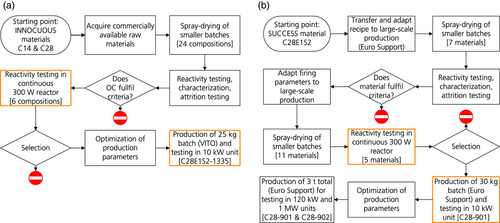
In both projects, different research groups contributed with their expertise to the development of calcium manganite–based materials. In the Innocuous project, this involved investigations of redox kinetics and sulfur tolerance,12-14 material screening and evaluation of spray-drying parameters using batch testing,15-17 and continuous operation in two chemical-looping combustors with nominal fuel inputs of 300 W and 10 kW.18-21 At a larger scale, the materials C14 (CaMn0.9Mg0.1O3−δ) and C28 (CaMn0.775Mg0.1Ti0.125O3−δ) were investigated in a 120 kW CLC unit.22, 23 An overview of the main project results is available.4
In the ensuing Success project, the focus was on raw material substitution to reduce the total costs of production and on upscaling of oxygen-carrier production to a multitonne scale. Flemish Institute for Technological Research NV (VITO) together with Euro Support produced the oxygen-carrier materials through spray-drying and upscaled the process.24 Spray-drying production parameters were investigated and specific tests, such as sulfur tolerance, were conducted.25, 26 Furthermore, different materials were screened in batch testing,27 and operational tests were conducted in CLC units with 300 W and 10 kW nominal fuel input, respectively, the results of which are presented here. Further operational studies were made in a differently designed 10 kW unit and a 120 kW CLC unit, including investigations of ageing and sulfur tolerance.28 Ultimately, experiments on a pilot scale, i.e., in a continuous reactor with nominal fuel input of 1 MW, were conducted.29 A project overview is given by Penthor et al.30
The development work described here has a focus on gases containing mainly methane, such as natural gas. The parallel work with oxygen carriers for solid fuels has been more focused on materials of low cost such as manganese, iron, and ilmenite ores. Although these materials generally show low reactivity toward methane, they show better performance for the syngas. Furthermore, CaMnO3 is likely irrelevant for use with coal because of its sensitivity to sulfur.13, 31 However, it could well be relevant for biomass and similar fuels of low sulfur content,32 and a batch of spent C28-902 material, diluted with ilmenite, from the operation at the TU Darmstadt has been successfully used with biogenic fuels in a 100 kW unit.33
1.3 Scope
The focus of this article is on the investigation of different calcium manganite–based oxygen-carrier materials produced in the Success project. This involves operation of these materials in two chemical-looping combustors of 300 W and 10 kW and characterization of materials before and after operation.
2 Experimental Section
2.1 Chemical-Looping Test Units
2.1.1 300 W Unit
The laboratory-scale continuous 300 W unit required approximately 250–400 g of oxygen-carrier particles, depending on their density. The reactor was 300 mm high and had two reactor chambers: an AR fluidized with air and an FR, here fluidized with methane. The FR had a cross-section of 25 mm × 25 mm, whereas the base of the AR was 25 mm × 42 mm and contracted to 25 mm × 25 mm in the riser section. Figure 3 shows the working principle of the reactor unit: high gas velocities caused the particles to lift out of the AR and to enter the gas–solid separator placed on the top flange of the reactor unit (not shown in the figure). The particles fell and entered the inlet of the J-type loop seal (downcomer). This caused particles at the outlet of the loop seal to fall onto the bubbling bed of the FR (through the return orifice). From the bottom of the FR, the particles flowed back into the AR via the lower loop seal. The AR was fluidized with air, the loop seals were fluidized with argon, and the FR was fluidized with either methane (fuel operation) or argon (determination of CLOU behavior).
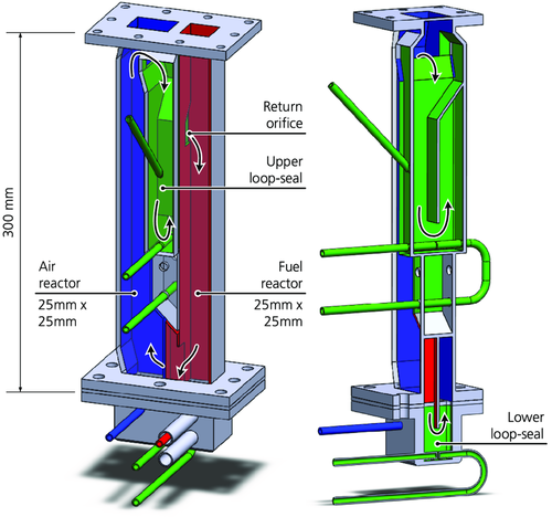
The off-gases from the reactors were separately cooled to 4 °C and filtered. The FR flue gas passed a water seal, which generated a slight overpressure in the FR and reduced leakage of air from the AR into the FR. The dried gases were analyzed for CO, CO2, CH4 (all IR sensors), and O2 (paramagnetic sensors). The FR flue gas was also analyzed in a gas chromatograph to verify these gas species and to further quantify N2 and H2.
2.1.2 10 kW Unit
The 10 kW laboratory-scale chemical-looping reactor system was constructed in 2002, and was used to perform the first successful demonstration of continuous CLC in 2003.34 A schematic of the unit is shown in Figure 4a.
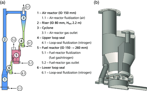
The AR (ID 150 mm) tapered down to the riser (ID 80 mm), which drove the global circulation of solids. After the riser, gas and particles were separated in the cyclone. From the cyclone, particles fell into a loop seal that prevented gas leakage between AR and FR. From the exit of the loop seal, particles flowed into the bubbling bed of the FR. The FR was equipped with a vertical separation wall to prevent particles from bypassing the bed (see Figure 4b). Particles left the FR through an overflow exit, which led the particles, via the second loop seal, back to the AR. Approximately 14–20 kg of oxygen-carrier particles were required to operate this unit.
The flue gases from AR and FR were first passively cooled through finned pipes before sample streams were extracted and led to a gas conditioning system. After the gas conditioning system, where the gas was cooled to 4 °C and filtered, CO, CO2, CH4, and O2 were measured continuously by infrared and paramagnetic sensors, respectively. An additional analysis of the FR flue gas by a gas chromatograph was conducted to quantify N2 and H2. Not all particles were removed in the cyclone and, therefore, the cyclone off-gas, which was the AR flue gas, was led to a bag filter, which captured elutriated particles and fines, before the filtered gas went to the stack. The FR flue gas passed through a water seal, which had the dual purpose of collecting condensed steam and controlling the pressure in the FR.
2.2 Oxygen-Carrier Production by Spray-Drying
Spray-drying is a scalable method of producing spherical particles up to a multitonne scale. Initially, a slurry was produced that contained ground, raw materials as well as a binder. The slurry was then fed through a spray nozzle, where spherical droplets were formed, into a stream of warm air, where the droplets solidified. The resulting dry powder was then sieved to a desired size fraction, which was then heat treated in box furnaces at more than 1000 °C in air (cf. Table 1). During heat treatment, the oxygen-carrier particles were placed in saggars, i.e., ceramic containers suitable for high temperatures, where they formed a fixed, nonstirred bed. When production was scaled up from a batch size of less than 1 kg up to several tons, the size of the saggars and the number of saggars per box furnace were increased.
| Oxygen-carrier material notation | Sintering temp. [°C] | CLC tests conducted [h] | ||
|---|---|---|---|---|
| 300 W | 10 kW | |||
| [A]a) | C14-Td) (reference) | 1300 | 16 | 55 + 41 |
| C28-TAe) (reference) | 1300 | 40 | 100 | |
| [B]b) | C28-E1Ae) | 1350 | 35 | – |
| C28-C1Ae) | 1350 | 13 | – | |
| C28-C2Ae) | 1350 | 38 | – | |
| C28-E1S2e) | 1335 | 37 | 24 | |
| C28-E1S1e) | 1335 | 36 | – | |
| C28-C2S1e) | 1335 | 26 | – | |
| [C] c) | C28-E3e), f) | 12801 | 7 | – |
| C28-E3e), f) | 1320 | 10 | – | |
| C28-E3e), f) | 12802 | 3 | – | |
| C28-E5e), f) | 1310 | 3 | – | |
| C28-E5e), f) | 1100 | 4 | – | |
| C28-901e), f) | 1100 | 11 | 110 | |
- a) [A] Reference materials (Innocuous project);
- b) [B] raw material substitution;
- c) [C] upscaling;
- d) C14 … CaMn0.9Mg0.1O3−δ;
- e) C28 … CaMn0.775Mg0.1Ti0.125O3−δ;
- f) -E3, -E5, -901 … spray-drying batch numbers (same sources of Mn and Ti as E1S2). All other suffixes in oxygen-carrier notation refer to raw materials used (cf. Table 2).
2.3 Oxygen-Carrier Materials
This work presents results of 14 different calcium manganite-based materials that were tested in continuous chemical-looping operation. These materials represent only a fraction of all calcium manganite–based materials produced during development. Spherical particles in the size fraction of approximately 100–200 μm were produced by spray-drying and subsequent sintering. The reference materials, involving the use of different raw materials, were produced by VITO, whereas materials subsequently selected for upscaling were produced by Euro Support (cf. Table 1).
Before a material was considered adequate for testing in the 300 W unit, it had to show a sufficiently high reactivity in batch experiments, where only a few grams of oxygen carrier were tested, as well as a sufficiently high resistance to mechanical attrition.27 After testing in the 300 W unit, to be suitable for investigation in the 10 kW unit, a material had to show low rates of attrition and degradation as well as a high conversion of fuel during continuous testing in the 300 W unit.
All oxygen carriers examined were based on calcium manganite with a perovskite structure, i.e., CaMnO3–δ, where δ expresses an oxygen deficiency. This type of material has so-called CLOU properties, i.e., it releases gas-phase oxygen in the FR, which can react directly with the fuel.11 This usually leads to an improved fuel conversion as compared with materials without CLOU properties, and, consequently, less oxygen carrier is needed to achieve similar levels of fuel conversion.35
Table 1 shows an overview of the different materials tested in the 300 W and 10 kW units. Two main compositions were studied, indicated by C14 and C28, where the former was CaMn0.9Mg0.1O3−δ and the latter was CaMn0.775Mg0.1Ti0.125O3−δ. The addition of small amounts of magnesium (Mg) to the perovskite structure was found to improve fuel conversion, mechanical stability, and fluidization properties.16 Similarly, small amounts of titanium (Ti) decreased the propensity of decomposition of the reactive phases.10
Table 2 shows an overview of the raw materials used to produce the oxygen-carrier materials shown in Table 1. These raw materials represent only a fraction of all raw materials tested in the development process. In total, 13 different sources of manganese were used, which had a purity between 71% and >99%. In addition, five different titanium sources were tested, which had a purity of 98.5% or more. In total, 24 different material compositions were produced and sintered at usually two different temperatures, which yielded 42 different batches produced.
| Notation (see Table 1) | Mn/Ti oxide | Purity [wt%] | Main impurity elementsa) | Raw material, supplier | |
|---|---|---|---|---|---|
| T | Mn3O4 | >99 | – | – | Trimanox, Chemalloy |
| E1 | Mn3O4 | 96 | – | Fe | Colormax P, Elkem |
| C1 | MnO2 | 81 | – | Fe, Si, Al | CDMA (ground Mn ore), Erachem-Comilog |
| C2 | Mn3O4 | 94 | – | Fe, Si, Al, P | Hausmannite LM type, Erachem-Comilog |
| A | TiO2 (rutile) | 99 | .9 | – | TiO2 rutile, Alfa Aesar |
| S1 | TiO2 (rutile) | >99 | – | – | Sachtleben TR, Sachtleben |
| S2 | TiO2 (anatase) | >99 | – | – | Sachtleben M211, Sachtleben |
- a) All impurities are in oxide phase.
2.4 Data Evaluation and Oxygen-Carrier Characterization
2.4.1 Fuel Conversion (300 W and 10 kW Units)
2.4.2 Solids Circulation and Oxygen-Carrier Conversion (10 kW Unit)
The true circulation of solids was approximately and indirectly determined with a method that consists of two parts.
Here, the method was adapted and tested for the 10 kW unit. A similar method of determining solids circulation through injection of char batches had previously been applied in the 300 W chemical-looping reactor.38, 39
2.4.3 Oxygen-Carrier Characterization
The different oxygen-carrier samples were characterized by measuring particle size distribution, bulk density, and crystalline phase composition. Attrition was measured in situ and in a customized jet-cup attrition test rig.
Particle size distribution was measured through stacked test sieves placed in a Retsch sieve shaker. A cumulative particle size distribution curve yielded the particle sizes that correspond to 10, 50, and 90 wt% of the sample, i.e., D 10, D 50, and D 90.
The bulk density of a sample of particles was determined on the basis of standard ISO 3923-1:2008. A powder sample was poured through a funnel, which had a defined outlet, and which was placed at a defined height above a test container. Excess material on top of the container was leveled without compressing the sample, and the resulting content, i.e., weight and volume, yielded the poured bulk density.
Semiquantitative X-ray powder diffraction (XRD) analysis was performed with two different X-ray powder diffractometers, at VITO using a Philips X'Pert diffractometer with PANalytical X'Pert Pro software with Cu Kα radiation (λ = 1.5406 Å) at 40 kV and at 2Θ-interval 5°…120°, and at Chalmers University of Technology using a Siemens D5000 diffractometer with a thin-film detector and Cu Kα1/2 radiation at 45 kV and 40 mA at 2Θ-intervals 10°…105° together with the software used is DIFFRAC.SUITE EVA, version 4.2.2.
Attrition in the 10 kW unit was determined by quantifying fines captured in the bag filter. The off-gas from the cyclone, Stream 3.1 in Figure 4a, was cooled and led through a bag filter, where particles and fines larger than 2 μm were captured. Here, fines are the fraction of the bag filter content smaller than 63 μm. In parallel, the off-gas from the FR, i.e., Stream 5.2 in Figure 4a, was cooled and led through a water seal, where particles were retained. Due to the low gas velocities, only fines were normally elutriated from the FR. The bag filter downstream the AR was emptied, and its content sieved at least once per day, and the water seal was emptied and filtered about once per week.
The attrition index is a standardized measurement performed with 5 g of oxygen-carrier particles in the size range 125–180 μm to determine mechanical attrition. The test was conducted at room temperature and the particles were exposed to an air jet at about 100 m s−1 while rotating in a conical cup. The stresses induced in that way were assumed to resemble the grid region and the cyclone inlet in industrial-scale units,40 albeit the conditions were more severe to give significant results in only 1 h.
3 Results
3.1 Experiments in 300 W Unit
3.1.1 CLOU Properties
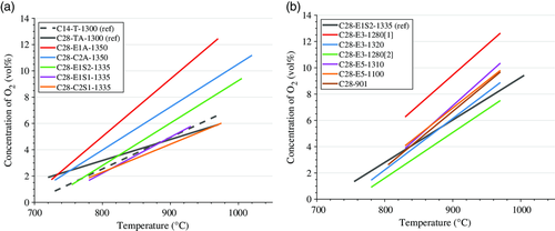
Figure 5 shows the release of gaseous oxygen in the FR under inert conditions at different temperatures. All materials show a considerable CLOU effect, i.e., oxygen released into inert atmosphere, that increases with fuel-reactor temperature. The CLOU properties vary clearly for different raw materials and sintering temperatures used (see Figure 5a). For upscaled materials, i.e., in Figure 5b, a clear correlation to the sintering temperature is not visible: the initial, unoptimized materials (C28-E3-12801 and C28-E3-1320) show the lowest CLOU effect, followed by the material C28-E5-1100 and the material with highest sintering temperature (C28-E5-1310). The strongest CLOU effect is achieved by C28-E3-12802 which also had the lowest concentration of oxygen in the AR. It should be stressed that the combination of relatively high circulation rates and relatively low flow of inert gas means that the concentration of oxygen at the outlet of the FR is likely limited by thermodynamics. Thus, the rates of release cannot be estimated from this data. However, the results clearly show a strong oxygen uncoupling effect of all calcium manganite–based materials produced.
| Oxygen-carrier material notation | Temperature profile [°C] | Number of data points used for model fitting [–] | Coefficient of determination, adjusted R2 [–] |
|---|---|---|---|
| C14-T-1300 (ref.) | 700–750–800–850–900–950 | ≈650 | 0.95 |
| C28-TA-1300 (ref.) | 735–790–845–900–950 | ≈650 | 0.94 |
| C28-E1A-1350 | 695–745–800–850–900–950 | ≈650 | 0.98 |
| C28-C2A-1350 | 700–750–800–850–900–950–1000–900 | ≈1150 | 0.97 |
| C28-E1S2-1335 | 775–830–880–930–985 | ≈700 | 0.98 |
| C28-E1S1-1335 | 800–855–910 | ≈250 | 0.97 |
| C28-C2S1-1335 | 800–850–900–955 | ≈550 | 0.94 |
| C28-E3-12801 | 850–900–950–905 | ≈600 | 0.91 |
| C28-E3-1320 | 800–850–900–925–950–900–845 | ≈1050 | 0.98 |
| C28-E3-12802 | 800–850–900–925–950–900–850 | ≈950 | 0.94 |
| C28-E5-1310 | 850–900–950–900 | ≈800 | 0.95 |
| C28-E5-1100 | 850–900–925–950–900 | ≈650 | 0.95 |
| C28-901 | 825–875–930–950–895 | ≈600 | 0.95 |
The fitted lines in Figure 5 are simple linear regressions models based on data generated in the CLOU characterization test. Such a test consisted of a variation of reactor temperature, while oxygen-carrier particles were circulated between AR and FR. The FR was fluidized with 1 Ln min−1 of argon, and the AR was fluidized with air. Here, the resulting concentration of oxygen at the outlet of the AR was between 17.0 and 19.6 vol%. Table 3 shows details of the CLOU characterization tests, i.e., temperature profile and number of data points used for the fitting of the model, as well as modeling results, i.e., coefficient of determination, adjusted R2. The coefficient of determination was usually well above 0.9, which indicates a good agreement between the models and the experimental data.
3.1.2 Fuel Conversion
Figure 6 shows methane conversion against specific fuel-reactor bed mass for the oxygen carriers produced with substituted raw materials, whereas Figure 7 shows conversion of the upscaled materials. The values shown are averages over periods of steady-state operation at 900 and 950 °C, respectively.
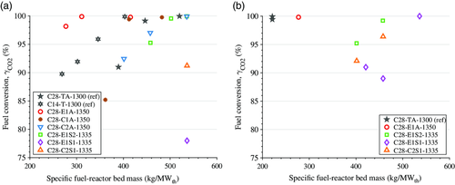
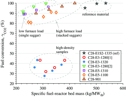
All oxygen-carrier materials achieved very high levels of methane conversion, which was well above 90% for most materials. An exception from this is the two initial upscaled materials that were not optimized, i.e., C28-E3-12801 and C28-E3-1320. At 900 °C, the performance of the material C28-E1S2-1335 came close to that of the reference oxygen-carrier from the Innocuous project, C28-TA-1300, whereas at 950 °C its performance was somewhat lower. During upscaling, all materials, except the high-density samples, which had reacted with the saggars during sintering (see Figure 7), were able to match the performance of the material C28-E1S2-1335, i.e., the reference material using low-cost raw materials.
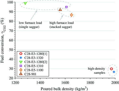
3.1.3 Oxygen-Carrier Properties
Figure 8 shows the correlation of reactivity of the different oxygen-carrier materials produced during the upscaling process and the bulk density of the materials. The reactivity was chosen to be expressed through fuel conversion, i.e., the CO2 yield , at 900 °C in the FR and at a specific fuel-reactor bed mass of 300 kg MWth−1, based on the data shown in Figure 7. The density of the particles clearly increases with increasing sintering temperature. However, initial sinterings with stacked-saggar configuration (samples C28-E3-1320 and C28-E3-12801), which is required for large-scale production, showed a higher density and a significantly lower fuel conversion in the 300 W tests (see Figure 8). The main difference between single- and stacked-saggar firings is believed to be the extent of gas exchange, which is limited when using a stacked configuration, and which could cause conditions with low oxygen concentration. Consequently, the sintering temperature had to be reduced significantly to achieve a density and reactivity similar to that of materials sintered in single saggars: the materials C28-E5-1100 and C28-901 were sintered in stacked saggars and show a similar density and reactivity as compared with materials sintered in single saggars at a temperature more than 200 °C higher.
3.2 Experiments in 10 kW Unit
3.2.1 Solids Circulation and Oxygen-Carrier Conversion
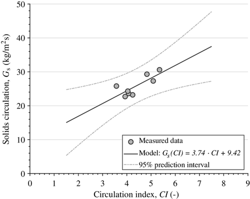
The circulation of the solid oxygen carrier was measured by means of addition of batches of solid fuel, here lignite char, for different superficial gas velocities in the riser. Solids circulation is expressed as a mass flux, i.e., normalized with respect to the cross-sectional area of the riser, to allow comparison to other CFB units. Based on the solids circulation determined via the char injection method, a linear model for the solids circulation as a function of the circulation index (see Equation 2) was established. Both measured data and model are shown in Figure 9 together with upper and lower bounds for a prediction interval with 95% confidence. Close to the measured data with respect to the circulation index, the interval between the upper and lower bounds corresponds to about 40% of the target value.
Oxygen-carrier conversion and oxygen deficiency are estimated based on the modeled solids circulation and the oxygen consumption in the AR (Equation 5). Figure 10 shows the solids conversion, expressed as the mass-based difference between AR and FR, ω AR − ω FR, as well as the difference in oxygen deficiency in the oxygen-carrier material between FR and AR, δ FR − δ AR. Oxygen-carrier conversion is shown against specific fuel-reactor bed mass (Figure 10a) and against AFR (Figure 10b). Data are shown for two different intervals of solids circulation, i.e., 15–22 and 22–29 kg m−2 s−1, and for three different intervals between 920 and 980 °C, respectively. Two general trends can be seen in the figure. If it is assumed that oxidation in the AR is constant and complete, the results indicate that bed material reduction in the FR 1) increases with less bed material in or more fuel input to the FR; 2) decreases if the circulation of bed material is increased; and 3) increases at higher temperatures in the FR.

Observations (1) and (2) can be explained by the commonly observed decreasing oxygen-carrier reactivity as oxygen-carrier reduction increases. Consequently, changes in oxygen-carrier reduction per unit of fuel added are highest in the beginning and decrease as more fuel is added. At higher rates of solids circulation, more oxidized oxygen carrier is added to the FR, which decreases the average degree of reduction in the FR. This, in turn, increases the average oxygen-carrier reactivity, and the average oxygen-carrier reduction per unit of fuel added increases. Observation (3) can be explained by a change in thermodynamic equilibrium, which causes more oxygen to be released (cf. Figure 5) or, in case of a direct reaction of the fuel with the oxygen carrier (in addition to CLOU), a higher reactivity.
3.2.2 Fuel Conversion
Fuel conversion expressed as the CO2 yield, , is shown against the AFR for different intervals of the fuel-reactor temperature (see Figure 11). Fuel conversion increases if the AFR is increased or if the fuel-reactor temperature is increased. A higher temperature increases oxygen release by the oxygen carrier (see Figure 5) as well as methane reactivity. A higher AFR, i.e., higher oxygen-carrier circulation and/or lower fuel input, could mean more reactive oxygen carrier in case of a direct reaction (in addition to CLOU) between fuel and oxygen carrier (cf. Section 3.2.1).
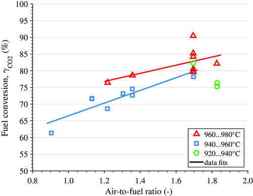
Figure 12 shows fuel conversion of different materials, i.e., Success materials C28-901 and C28-E1S2 as well as reference materials (Innocuous) C14-T and C28-TA, at varied fuel input (the bed height in the FR of the 10 kW unit can be considered as constant), i.e., specific fuel-reactor bed mass, and varied fuel-reactor temperature. Fuel conversion increases for all materials with decreasing fuel input, which means that the fuel-reactor bed on average is less reduced and has thus a higher reactivity.

As can be seen from Figure 12, the material C28-E1S2 was able to achieve comparable fuel conversion as the reference materials, i.e., C14-T and C28-TA, yet at a slightly higher temperature. For the upscaled material C28-901, the fuel conversion achieved was significantly lower, usually between 70% and 85%. It should be mentioned that the upscaled material was operated for over 60 h at high temperature with a significant gas leak upstream of the FR, Stream 5.1 in Figure 4a, which could have affected the oxygen-carrier material, although this is not known. Note that all experimental data shown for material C28-901 in the 10 kW unit were recorded after the gas leak was mended.
The reference materials C14-T and C28-TA have also been tested in a continuous CLC reactor system at the TU Wien. The results were comparable to the ones achieved here, though higher levels of fuel conversion were achieved in the reactor system of the TU Wien. With the material C14, the CO2 yields achieved at the TU Wien were between 95% and 99% at about 400 kg MW−1 in the FR at 900–970 °C, whereas with the material C28 only 300 kg MW−1 were needed to achieve a similar fuel conversion at similar temperatures.22, 23 The reason for the higher conversion in the unit at the Wien is believed to be due to the circulating bed in the FR in contrast to the bubbling bed of the 10 kW unit used here. A circulating bed is likely to have better mixing, i.e., better contact between oxygen carrier and fuel, and might have a longer contact time as the oxygen carrier is distributed along the height of the reactor.
The oxygen-carrier material C28-902, which is similar to the material C28-901 used here, was tested at TU Darmstadt in a continuous CLC unit with a nominal fuel input of 1 MW.29 The raw materials used for C28-902 and the production method were the same as for C28-901, but due to the larger batch size, 2.2 t in total, the calcination process might have led to different material properties. The group at TU Darmstadt compared their results with the results from TU Wien with a C28 material that was similar to C28-TA used here, and which was made from different raw materials than C28-901 and C28-902.22 Conversion at TU Darmstadt was lower but in line with the results from TU Wien as the specific fuel-reactor bed mass was significantly lower. This differs somewhat from the results achieved here, where the material C28-901 achieved significantly lower fuel conversion than the reference material C28-TA. The reason for the seemingly better performance at TU Darmstadt might have been due to the fact that the FR of their unit is a CFB and/or that the material properties were different from those of the material C28-901 used here.
3.2.3 Oxygen-Carrier Analysis and Lifetime
Particle analysis reveals that particle size distribution and bulk density do deviate significantly between the fresh sample and the sample taken from the 10 kW unit at the end of the campaign, i.e., after 110 h of fuel operation (see Table 4). However, the sample of the material that was used in the 300 W unit indicates that bulk density may change at different operational conditions. It seems unlikely that the different bulk densities are a consequence of differences in size distribution; the used 10 kW sample from the AR contains less fines and more coarse particles than the fuel-reactor sample as would be expected, and the used 300 W sample has a similar, slightly narrower size distribution than either of the 10 kW samples.
| Property | Unit | Before testing | After testing | |
|---|---|---|---|---|
| 300 W unit (10.7 h) | 10 kW unit (110 h) | |||
| Bulk densitya) | Kg m−3 | 1570 | 1830 | 1630 (AR)1590 (FR) |
| Particle sizes D10, D50, D90b) | μm | 100, 150, 190 | 100, 140, 170 | 110, 150, 180 (AR)90, 130, 170 (FR) |
- a) Poured bulk density determined on the basis of standard ISO 3923-1;
- b) Points from particle size distribution curve with particle sizes larger than 10, 50, and 90 wt%, respectively, of the sample.
The interpretation of the XRD diffractograms shows that most of the materials consist of the desired perovskite structure throughout the whole test campaign in the 10 kW unit. The perovskite-structured phases that were detected contain Ca, Mn, Ti, and O and Ca, Ti, and O, respectively (see Table 5). About a third of the samples consist of calcium manganese oxides CaMn2O4, Ca2MnO4, and Ca2Mn2O5. Magnesium was only detected in the oxide form MgO, and not as part of any other phase. The analysis performed by VITO (see Table 5) seems to indicate that the fraction of the phase CaMn0.9Ti0.1O2.961 is slightly reduced over time, which might be a result of a material decomposition. However, this is uncertain as the analysis is semiquantitative and no reliable species balance can be conducted.
| State of oxygen-carrier sample | Crystalline phases identified though XRD analysis |
|---|---|
| Fresh (VITO) | CaMn0.9Ti0.1O2.961 (50–80%), |
| CaMn2O4 (10–20%), CaTiO3 (5–15%), | |
| Ca2MnO4 (<10%), MgO (<5%) | |
| After 7.2 h of fuel operation (VITO) | CaMn0.9Ti0.1O2.961 and/or CaMn0.7Ti0.3O2.94 (50–80%), |
| CaMn2O4 (10–25%), CaTiO3 (5–10%), | |
| Ca2MnO4 (5–10%), MgO (<10%) | |
| After 75 h of fuel operation (VITO) | CaMn0.9Ti0.1O2.961 (60–80%), |
| CaMn2O4 (5–20%), CaTiO3 (5–10%), | |
| Ca2MnO4 (<10%), MgO (<5%) | |
| After 107 h of fuel operation (VITO) | CaMn0.9Ti0.1O2.961 (40–60%), |
| CaMn0.5Ti0.5O2.925 (10–20%), CaMn2O4 (10–20%), | |
| CaTiO3 (10–15%), MgO (<5%), Ca2MnO4 (<5%) | |
| After 110 h, end of campaign, AR sample (Chalmers) | CaMnO2.95…3.15 and/or CaMn0.9Ti0.1O2.962, |
| CaMn0.7Ti0.3O2.94, Ca2Mn2O5, CaMn0.5Ti0.5O2.924…3.0 | |
| CaMn2O4, CaTiO3 | |
| After 110 h, end of campaign, FR sample (Chalmers) | CaMnO2.75…3.15 and/or CaMn0.9Ti0.1O2.962, |
| CaMn0.5Ti0.5O3, CaMn2O4, Ca2Mn2O5, CaTiO3 | |
| After 110 h, end of campaign, FR agglomerates (Chalmers) | CaMnO2.8…3.15 and/or CaMn0.9Ti0.1O2.962, |
| CaMn2O4, Ca2Mn2O5, CaTiO3 |
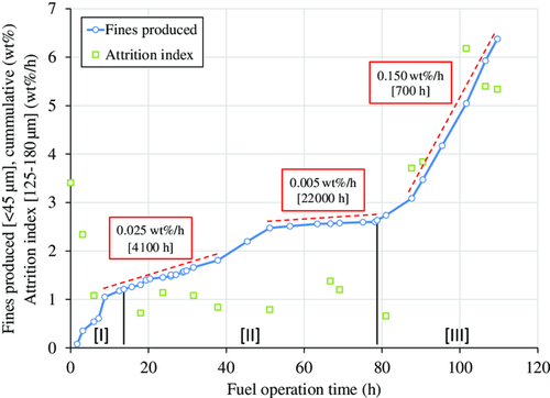
The rate of fines production during operation in the 10 kW unit was used to estimate particle lifetime (see Figure 13). Fines production changed significantly throughout the campaign. The fresh materials contained up to 4 wt% of particles below 90 μm, and, additionally, a fraction of irregular particles, e.g., microagglomerates, hollow spheres, and donut-shaped particles, which is common for spray-dried materials. These initial fines and irregular particles are likely the reason for the initially high rates of fines production, i.e., during phase I. After these initially high rates, fines production was rather low until about 80 h of fuel operation, i.e., throughout phase II. During this phase there was a significant leakage of fuel upstream of the FR, which impaired fluidization in the FR and circulation in the whole 10 kW unit. After the fuel line was repaired and fluidization and circulation were reestablished, the rate of fines production increased significantly from phase II to phase III. Samples of the filter content in the fraction of 125–180 μm were used to determine the attrition index throughout the campaign. The development of the attrition index over fuel operation time fits the observed rates of fines production well (see Figure 13). Relatively high attrition indices were recorded when fines production in the 10 kW was high and vice versa. This indicates that particles inside the reactor were not damaged during phase II, but became less resistant to attrition during phase III.
Values for lifetimes estimated based on operation in the 10 kW unit as well as attrition indices determined for fresh and used particles are shown in Table 6. In comparison to other, similar materials operated in the 10 kW unit (see Table 6), the material C28-901 achieved a rather low lifetime and exhibited relatively high attrition indices at the end of the campaign. The tests conducted at TU Darmstadt with the material C28-902 yielded a similar lifetime to the one estimated here with the material C28-901, i.e., 500 h as compared with 700 h.29 The material C28-902 was produced in a similar manner as the material C28-901; the only differences between the two materials are the calcination furnaces used and the calcination parameters, which differed slightly.
| Oxygen-carrier material | Fuel operation [h] | Estimated lifetime [h] | Attrition index [wt% h−1] | |
|---|---|---|---|---|
| Fresh particles | Used particles | |||
| C14-T | 55 | 12 000 | 1.03 | 0.58 |
| C28-TA | 99 | 9000 | 8.86 | 1.93 |
| C28-E1S2 | 24 | 5000 | 3.08 | n/a |
| C28-901 | 110 | 700 | 3.41 | 2.69 (AR)2.10 (FR) |
| C28-902 (1 MW)a) | 50 | 500 | 2.8 | 0.4–0.5 |
- a) Values taken from Ohlemüller et al.29
Upon opening and emptying the 10 kW unit, agglomerates were detected in the FR and in the upper loop seal of the unit. The agglomerates were soft and could be easily crushed between fingers. About 20 wt% of the content of each vessel consisted of agglomerates between 0.5 mm up to about 6 cm. The agglomerates in the loop seal may have been formed as a result of high temperature as there was much heating cable wrapped around the loop seal, which also caused stains on the outside of the loop seal. The agglomerates in the FR may have been formed as a result of local zones of bad mixing and/or high reduction. An XRD analysis performed with a sample of the agglomerate indicated that the agglomerate has a phase composition that corresponds to that of the samples from AR and FR. If the XRD analysis is representative, agglomeration may have been caused by high temperatures rather than high reduction.
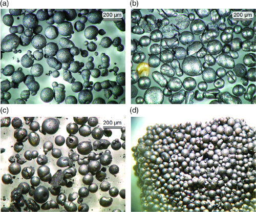
Figure 14 shows light microscope images of fresh particles, particles at the end of the campaign from AR and FR, and an agglomerate from the FR. The fresh batch visibly contains a fraction of small and very small particles, i.e., about 5 wt% are below 100 μm. Most of the particles appear to be spherical and intact. Visible defects include satellites, nonspherical particles, and microagglomerates, i.e., two particles molten together. The samples taken at the end of the campaign appear mostly spherical and undamaged, though a significant fraction consists of broken, hollow, donut-shaped or cracked spheres, and microagglomerates. The sample from the FR contains fines, whereas the sample from the AR does not. This is believed to be due to the higher gas velocities in the AR. The agglomerate from the FR looks like a tight packing of particles, and no molten bridges are visible between the particles. This confirms the observation that the agglomerates are soft and easily crushed between the fingers. It is speculated that in an industrial-scale process such agglomerates could only be formed in zones of improper fluidization, but would dissolve into individual particles once they enter a zone of proper fluidization. Therefore, the agglomerations observed are believed to be reversible and no threat to an industrial-scale process.
4 Conclusions
Calcium manganite–based oxygen-carrier materials with a perovskite structure were developed for the application of CLC of gaseous, sulfur-free fuels. As part of two major EU-financed projects, a significant number of materials have been produced using different raw materials and varying production parameters. These have been tested in a number of CLC pilot units, and the results of testing in two such reactors are described here.
It has become clear that the perovskite structure is simple to produce, also with highly heterogeneous and low-grade raw powders. The important CLOU property was seen for all oxygen-carrier materials made. Several of the oxygen-carrier materials produced with substituted raw materials could match the performance of the reference materials produced with high-purity raw materials, and several oxygen-carrier materials showed a combination of high reactivity and low attrition rates.
Production was also scaled up to a multitonne scale. During upscaling, the main challenges were related to the sintering process. Here, temperature gradients and inadequate gas exchange throughout large batches of material made the production of a material with homogeneous properties difficult. It is assumed that there is an optimal sintering temperature with respect to oxygen-carrier reactivity. However, there is a risk of oversintering the oxygen-carrier material, which resulted in a dramatical reduction in reactivity. With reactivity losses at stake, the upscaled materials were potentially undersintered. More experience with the box furnaces will help to produce an oxygen-carrier material with better properties. Another possibility of improving mixing and decreasing temperature and concentration gradients is to use rotary kilns for the sintering process instead of box furnaces.
Acknowledgements
The project Industrial steam generation with 100% carbon capture and insignificant efficiency penalty—Scale-Up of oxygen Carrier for Chemical-looping combustion using Environmentally SuStainable materials (SUCCESS) received funding from the European Union's Seventh Framework Programme for research, technological development, and demonstration (FP7-Energy) under grant agreement no. 608571.
Conflict of Interest
The authors declare no conflict of interest.


