Seismic fragility and life-cycle loss analyses of high-speed railway bridges supported by segmentally assembled round-end hollow piers
Abstract
The shortcomings of segmentally assembled round-end hollow-section piers (SRHPs), such as weak segment joints and poor energy-dissipation capacity, have limited their application in high-intensity earthquake regions. Therefore, this article particularly focuses on the seismic performance of SRHPs. Three high-speed railway bridges are designed, which are equipped with three different types of round-end hollow-section piers (RHPs): cast-in situ RHP (CRHP), segmentally assembled RHP with energy-dissipation bar (E-SRHP), and segmentally assembled RHP with low-yield point steel connection buckles (L-SRHP). Subsequently, three nonlinear finite element models of the corresponding bridges were established and validated by quasi-static test results. Furthermore, compared to CRHP, the seismic performance of E-SRHP and L-SRHP was evaluated from the perspectives of seismic fragility and life-cycle seismic loss. Research results revealed that the seismic fragility performance of the bridge with L-SRHP is the best among all three bridges, followed by the bridge with E-SRHP. Notably, the life-cycle cost considering seismic loss for E-SRHP is 83% of that for CRHP, whereas L-SRHP is only 65% of that for CRHP. In general, the high-speed railway bridge supported by L-SRHP possesses the best seismic performance and economic benefits among the three bridges, which shows promising application prospects in high-intensity earthquake-prone regions.
1 INTRODUCTION
Precast segmentally assembled piers (PSPs) have been gradually adopted in bridge projects due to their advantages, including superior self-centering capacity, high construction efficiency, high quality, and low environmental impact. In-depth research has been conducted to investigate the performance of bridges with PSPs. Seismic performance and seismic isolation effect are two critical research directions.
Seismic performance of PSPs is generally evaluated through numerical simulation,1-9 pseudo-static tests,4,7-17 or shake table tests.18 Mohamed et al. used three-dimensional nonlinear finite element models to analyze the seismic performance of PSPs made of concrete-filled FRP tubes. The results showed that aspect ratio, cross-sectional diameter size, pier size, and confinement have significant effects on the performance of piers. Chang et al. evaluated the seismic performance of PSPs with circular solid sections through quasi-static test results. This study found that the prestress provides self-centering forces for the piers that reduce seismic damage. Petros et al. conducted a shake table test on a new type of large-scale hybrid sliding-rocking post-tensioned segmental bridge system. The results showed that segmental joints with sliding as the dominant connection can not only provide self-centering capacity but also dissipate earthquake energy and mitigate damage.
Seismic isolation effect of PSPs is mainly achieved by setting internal energy-dissipation bars,5, 15 replaceable external dampers,9, 12, 16, 19 or adding friction energy-dissipation components between precast segments.2 Ou et al. set bonded longitudinal mild steel reinforcement within segment joints.20 The lateral strength of the columns can be improved by increasing energy-dissipation rebars. Optimum flag-shaped hysteretic behavior can be observed by setting the ratio to 5%. Cha et al.19 studied the cyclic response of precast composite hollow reinforced concrete (RC) columns. It was found that precast columns perform similarly to cast-in-situ columns. Yang figured out that fresh silicone can improve the energy-dissipation capacity of PSPs, but the shortcoming of shear-slip between segments cannot be fully made up.
Significant progress has been made in understanding the mechanical performance of PSPs. However, to properly evaluate a new bridge structural system, further assessment also should be made from the perspective of cost to evaluate the holistic properties. Bora et al. conducted a life-cycle cost assessment on structural frames using RC and reinforced engineered cementitious composites (ECC). Zheng et al.21 conducted a life-cycle resilience and loss assessment for smart bridges with shape memory alloy (SMA) cable–based bearings. Li et al.22 conducted a life-cycle cost assessment for high-speed railway continuous girder bridges designed with various seismic isolation schemes. Li et al.22 conducted fragility analysis and life-cycle seismic loss assessment for a seismic resistance bridge system with post-tensioning precast segmental ultra-high performance concrete bridge columns.
In summary, previous research has examined the seismic and vibration reduction performance of prefabricated bridge piers. From the research results obtained so far, it can be seen that prefabricated bridge piers have attracted the attention of many scholars due to their various advantages. However, there is scarce research on the seismic safety of prefabricated segmentally assembled round-end hollow-section piers (SRHPs) used in high-speed railway bridges, leading to safety risks in the application of such piers in high-speed railway projects. Therefore, this article analyzes the seismic safety of high-speed railway bridges using prefabricated SRHPs and proposes reasonable vibration reduction measures to enhance their seismic safety. The research findings provide important theoretical references and suggestions for the vibration reduction design of this type of pier and its safe application in high-speed railway projects. Furthermore, to further explore the potential economic value of using prefabricated bridge piers in high-speed railway bridge projects, this article combines the research methods on the economic feasibility of new structures discussed earlier and evaluates the economic rationality of applying prefabricated bridge piers in high-speed railway bridge projects from the perspective of seismic damage and risk throughout the entire life cycle. Quantitatively assessing the seismic losses throughout the life cycle of new high-speed railway bridges from an economic perspective is crucial for evaluating the economic benefits of deploying these bridges in high-intensity seismic zones.
2 NUMERICAL SIMULATION OF HIGH-SPEED RAILWAY BRIDGES
2.1 Quasi-static test results and modeling methods of high-speed railway bridge piers
2.1.1 Quasi-static test results of bridge piers
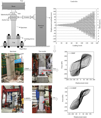
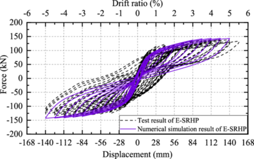
A typical PSP for the Yinchuan-Lanzhou High-Speed Railway was taken as a prototype. Two 1:5 large-scale specimens—a cast-in-situ RHP (CRHP) and an SRHP—were designed according to the prototype bridge pier. Both pier specimens had the same dimensions, with an effective height of 2800 mm, a cross-sectional wall thickness of 140 mm, and outer wall size of 1240 × 600 mm. C40 concrete was used for the piers. Eighty pieces of HRB400 bars with a diameter of 12 mm were used as longitudinal bars both in the inner and outer rings. HRB400 bars with diameters of 8 and 6 mm were used as stirrups and lacing bars, respectively. The quasi-static test results are shown in Figure 1.23
2.1.2 Modeling methods of bridge piers
- 1.
Modeling method for CRHP
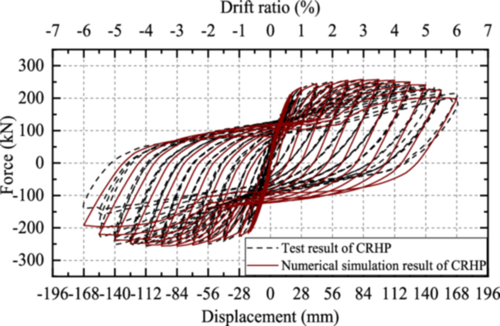
Using the OpenSees platform, the nonlinear finite element model of CRHP was established, and its seismic performance was analyzed (Figure 2). The pier was simulated using a nonlinear beam-column element based on the stiffness method theory. Concrete01 material was used to simulate the properties of concrete, and the constraint of the stirrup was considered in the simulation of the core concrete. ReinforcingSteel material was used to define the properties of rebar fibers, which can simulate fatigue behavior under cyclic load, buckling behavior, stiffness degrading, and crack behavior of steel rebars. The mesh fineness of the fiber will affect simulation accuracy, calculation efficiency, and convergence effect.24 Therefore, to ensure simulation accuracy, the number of fibers in the hollow section was determined as 356, and that in the post-casting section was 548 by calculation study. A comparison between the numerical analysis results and the test results is shown in Figure 3.
- 2.
Modeling method for segmentally assembled RHP with energy-dissipation bar (E-SRHP)
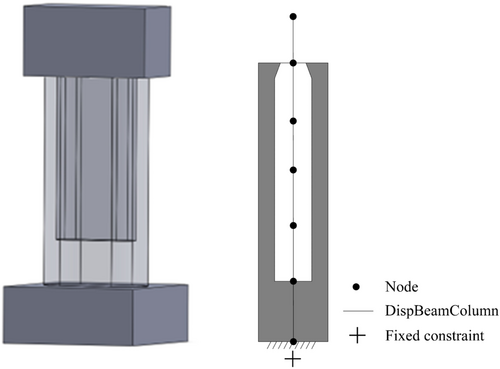
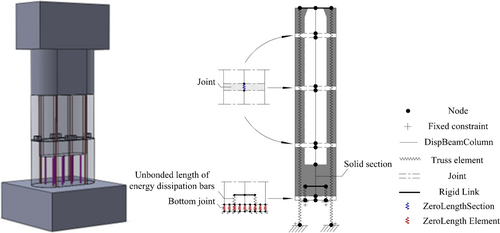
The finite element model of the E-SRHP specimen was established based on the OpenSees platform (Figure 4). The mechanical behavior of the protective layer concrete fibers and core concrete fibers was simulated using Concrete01 material, whereas the steel rebar fibers were simulated using Steel02 material.25 The prestressed tendons were simulated by Truss element and Steel02 material. The top nodes of the prestressed tendons and pier fiber model were connected by the rigid arms and the bottom nodes of the prestressed tendons were fixed. The energy-dissipation rebar in the bonded section was simulated using the same material as the ordinary rebars, which only established the energy-dissipation bar fiber at the corresponding position of the fiber section. The energy-dissipation rebar in the unbonded section was simulated by Truss element and Steel02 material, and the bottom of the energy-dissipation bar was subjected to fixed restraints.
To better simulate the stress characteristics of the bottom joint of the pier, the bottom joint was simulated using only compression springs and the elastic-no tension (ENT) material, and the bottom nodes of the element were fixed. The other joints were simulated using the ZeroLengthSection element and the ENT material, and the section fiber layout was consistent with the fiber division of adjacent sections. A comparison between the numerical analysis results and the test results is shown in Figure 5.
According to Figures 3 and 5, the skeleton curve of finite element results correlates well with the test results, indicating that the numerical results can depict the nonlinear mechanical behavior of CRHP and E-SRHP.
2.2 Design and modeling of high-speed railway bridges
Different from bridges with equal spans, high-speed railway bridges with unequal spans are more prone to suffer from pounding effects. The seismic safety of railway bridges is thus negatively affected. Considering bridges with both unequal spans and different round-end hollow-section piers (RHPs), three high-speed double-track railway simply supported girder bridges were designed to investigate seismic safety.
The design of these bridges was based on the Railway Engineering Construction general diagrams, a reference provided by the China Railway Economic Planning and Research Institute. The span distributions of these bridges are identical: 24 + 32 + 24 m. Other dimensional parameters of the three bridges are also the same. Schematic diagrams of the bridge structures are shown in Figure 6.
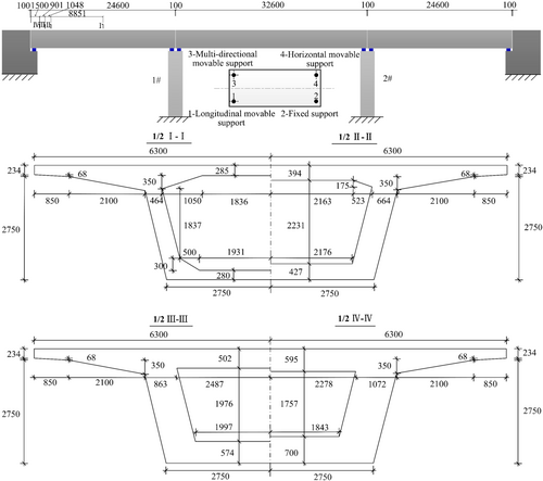
The girder was a concrete box girder with a single-box and single-cell design, which was 3052 mm in height, 12,600 mm in width, and made from C50 concrete. It is worth noting that different types of RHPs, including CRHP, E-SRHP, and segmentally assembled RHP with low-yield point steel connection buckles (L-SRHP), were used in different bridges.
2.2.1 Design of piers
- 1.
Design of the CRHP
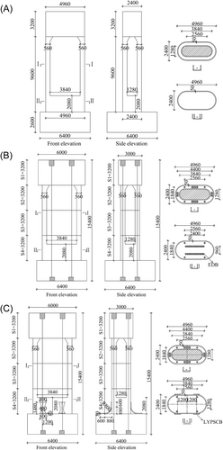
The effective height of the CRHP is 11,200; mm, as shown in Figure 7A. The cross-sectional wall is 560 mm in thickness, and the external dimension is 4960 × 2400 mm. The pier shaft is made of C40 concrete. A total of 288 HRB400 steel rebars with a diameter of 12 mm were used as longitudinal bars both in the inner and outer rings, resulting in a reinforcement ratio of 1.07%. HRB400 rebars with diameters of 8 and 6 mm were used as stirrups and lacing bars, respectively. The stirrup center spacing was 80 mm, which led to a stirrup ratio of 0.9%.
- 2.
Design of the E-SRHP
The E-SRHP was designed with four segments connected by prestressed steel strands, as shown in Figure 7B. Tensioning force in a single tendon was 34% of the standard value of ultimate tensile strength. The designed axial compression ratio of prestress was 5%. Other concrete materials, longitudinal rebars, stirrups, and structural dimensions are consistent with those of the CRHP. HRB400 reinforcement with a diameter of 35 mm was added as an energy-dissipation bar in the post-cast section at the bottom of the pier as a measurement for seismic isolation. The ratio of the energy-dissipation bar was 1.27%.
- 3.
Design of the L-SRHP
The structural drawing of the L-SRHP (Figure 7C) was consistent with that of the E-SRHP (Figure 7B), but there are differences in seismic isolation measures. Because the energy-dissipation bar was generally embedded in the postcast section of the SRHP, it is difficult to replace the energy-dissipation bar damaged in an earthquake. To address this issue, a low-yield steel point connection buckle (LPB) is adopted as an efficacious seismic vibration absorber that can be easily replaced after an earthquake. LPBs are installed at the joints between the bottom of the pier and the pile cap. The distribution of LPBs on L-SRHP is shown in Figure 7C, in which four LPBs were symmetrically installed at both the front and back surfaces of the pier. The section contribution rate of the LPB energy-dissipation section is 0.78%.
| Specimen | Reinforcement ratio (%) | Stirrup ratio (%) | Axial loading (kN) | Axial compression ratio (%) | Prestress (kN) | Shear-span ratio | Ratio of energy-dissipation bar (%) |
|---|---|---|---|---|---|---|---|
| CRHP | 1.07 | 0.9 | 524 | 7.5 | 0 | 4.7 | 0 |
| E-SRHP | 1.07 | 0.9 | 524 | 7.5 | 354 | 4.7 | 0.59 |
- Note: The net sections involved in the longitudinal reinforcement ratio and stirrup ratio in the table are calculated based on the hollow section of the pier shaft. The gross sections involved in the energy-dissipation bar ratio in the table are calculated based on the solid section of the pier shaft.
- Abbreviations: CRHP, cast-in situ round-end hollow-section pier; E-SRHP, segmentally assembled RHP with energy-dissipation bar.
| Type | Simulation object | Material | Property | Value | Unit |
|---|---|---|---|---|---|
| CRHP | Cover concrete fiber | Concrete01 | Concrete compressive strength | 31.6 | MPa |
| Concrete strain at maximum strength | 0.2 | % | |||
| Concrete crushing strength | 9.0 | MPa | |||
| Concrete strain at crushing strength | 0.4 | % | |||
| Core concrete fiber | Concrete01 | Concrete compressive strength | 34.3 | MPa | |
| Concrete strain at maximum strength | 0.217 | % | |||
| Concrete crushing strength | 27.3 | MPa | |||
| Concrete strain at crushing strength | 1.2 | % | |||
| Rebar fiber | ReinforcingSteel | Yield stress in tension | 460 | MPa | |
| Ultimate stress in tension | 650 | MPa | |||
| Initial elastic tangent | 200 | GPa | |||
| Strain corresponding to initial strain hardening | 0.3 | % | |||
| Strain at peak stress | 15 | % |
- Abbreviation: CRHP, cast-in situ round-end hollow-section pier.
| Type | Simulation object | Material | Property | Value | Unit |
|---|---|---|---|---|---|
| E-SRHP | Cover concrete fiber | Concrete01 | Concrete compressive strength | 28.6 | MPa |
| Concrete strain at maximum strength | 0.2 | % | |||
| Concrete crushing strength | 9.0 | MPa | |||
| Concrete strain at crushing strength | 0.4 | % | |||
| Core concrete fiber | Concrete01 | Concrete compressive strength | 34.3 | MPa | |
| Concrete strain at maximum strength | 0.217 | % | |||
| Concrete crushing strength | 27.3 | MPa | |||
| Concrete strain at crushing strength | 1.2 | % | |||
| Rebar fiber | Steel02 | Yield strength | 400 | MPa | |
| Initial elastic tangent | 195,000 | MPa | |||
| Energy-dissipation bar | Steel02 | Yield strength | 400 | MPa | |
| Initial elastic tangent | 195,000 | MPa | |||
| Joint | Elastic-no tension | Tangent | 100,000 | MPa |
- Abbreviation: E-SRHP, segmentally assembled RHP with energy-dissipation bar.
2.2.2 Nonlinear finite-element models of high-speed railway bridges established based on the OpenSees platform
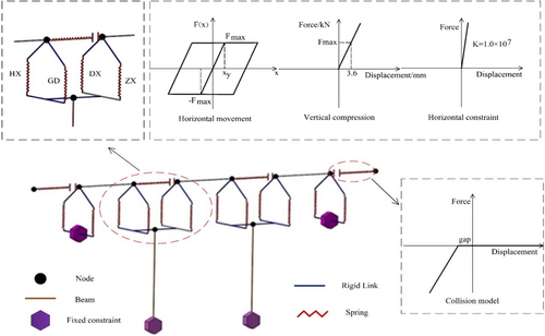
The girder was simulated using ElasticBeamColumn elements. The expansion joints between girders, as well as between girders and abutments, were simulated using Zero-Length elements with ElasticPPGap material. When the contact pounding phenomenon occurs, a contact model will be activated. The contact model is composed of only one connecting spring, which does not take energy loss during pounding into account, and the axial stiffness of the girder is taken as the pounding stiffness.26 Bearings were simulated using Zero-Length elements with different materials in different degrees of freedom. Steel01 was used to simulate the sliding bearing whose hysteresis curve was like that of ideal elastic–plastic materials. The corresponding sliding critical displacement and sliding friction coefficient are 3 mm and 0.02, respectively.27 Horizontal fixed and vertical compression were simulated using springs with different stiffnesses.28, 29 The bearings were connected to girders and piers through rigid links. The specific modeling method is illustrated in Figure 8.
3 SEISMIC FRAGILITY ANALYSIS OF HIGH-SPEED RAILWAY BRIDGES
3.1 Damage state
Substantial data collected from bridges after earthquakes have shown that piers and bearings are more vulnerable to earthquake damage than other components. Therefore, this article focuses on the damage to piers and bearings by quantifying the damage state. The damage states for CRHP, E-SRHP, and L-SRHP are determined from the results of the quasi-static test of piers, as given in Tables 4 and 5. The damage states of bearings are determined from research results in existing literature,30, 31 as given in Table 6.
| Level | Damage state | Damage characteristics | Drift ratio |
|---|---|---|---|
| 1 | Slight damage | The first bar yields | 0.0057 |
| 2 | Moderate damage | Local plastic hinge begins to form, the protective layer of concrete falls off, and visible cracks appear and develop | 0.035 |
| 3 | Extensive damage | The plastic hinge is fully formed, large crack width, and concrete spalling in the whole plastic hinge area | 0.05 |
| 4 | Collapse | Main reinforcement buckling, stirrup fracture, and core concrete crushing | 0.06 |
- Abbreviation: CRHP, cast-in situ round-end hollow-section pier.
| Level | Damage state | Damage characteristics | Drift ratio |
|---|---|---|---|
| 1 | Slight damage | Cracks begin to appear in the pier shaft | 0.0057 |
| 2 | Moderate damage | Obvious vertical cracks appear in the pier shaft and continue to develop | 0.01 |
| 3 | Extensive damage | Concrete spalling at joints | 0.03 |
| 4 | Collapse | Shear dislocation of joint, large area spalling of concrete | 0.045 |
| Level | Damage state | Displacement (mm) |
|---|---|---|
| 1 | Slight damage | 30 |
| 2 | Moderate damage | 100 |
| 3 | Extensive damage | 150 |
| 4 | Collapse | 255 |
3.2 Ground motion selection
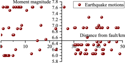
A hundred earthquake motion records were selected from the Pacific Earthquake Engineering Research Center (PEER). Distance from epicenter to fault and moment magnitudes of each earthquake is presented in Figure 9, based on which the influence of earthquake motion uncertainty on the results of fragility analysis can be fully considered.
3.3 Seismic fragility analysis of bridges
Bearings and piers are regarded as vulnerable components in a bridge system. Seismic damage probabilities of these components are linked using the boundary estimation method. It is considered that the bridge system is composed of a series of vulnerable bearings and vulnerable piers. In the most rigorous scenario, seismic damage to any component can be considered as damage to the whole bridge system. Based on this principle, the performance of the whole bridge system can be more conservatively evaluated.
3.3.1 Probabilistic seismic demand models
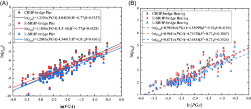
PGA was first set as the earthquake motion intensity parameter.39, 40 Subsequently, the probabilistic seismic demand models of piers and bearings in three high-speed railway bridges were established based on the above-determined earthquake motion intensity parameter, demand parameters, and failure quantification indices, as shown in Figure 10. According to models in Figure 10, the coefficient of determination in each probabilistic seismic demand model is larger than 0.75, which indicates that fitting results are good, and the established probabilistic seismic demand models are with high reliabilities.
3.3.2 Seismic fragility curves of bridge systems
Assuming that these three bridges are located in seismic areas with an intensity degree of eight. According to the code,41 0.1 g (E1) represents frequent earthquakes, 0.3 g (E2) represents design earthquake Ag, and 0.57 g (E3) represents rare earthquakes. These three indicators are used as the criteria to determine the damage probability of the three bridge systems. Based on the analysis theory of structural seismic fragility, the fragility curves of CRHP, E-SRHP, and L-SRHP were calculated and compared to further clarify differences in seismic performance levels among them.
According to the analysis and results in Figure 11A, the probabilities of slight damages of the CRHP, E-SRHP, and L-SRHP are very small under an E1 earthquake. The probability of slight damage to a bridge system with CRHP is 76.77% under an E2 earthquake, and these of bridge systems with E-SRHP and L-SRHP are 72.69% and 42.60%, respectively. The probability of slight damage to three bridge systems is near 100% under an E3 earthquake. To sum up, the probability of slight damage to the L-SRHP bridge system is the smallest among the three bridge systems. It can be illustrated that LPB takes effect at the beginning when piers start swinging in the earthquake, and the seismic isolation effect is significantly better than that of the embedded energy-dissipation bar.
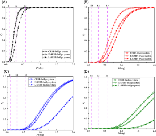
According to the analysis and results in Figure 11B, the probabilities of moderate damage to three bridge systems are all small under E1 and E2 earthquakes, and no damage occurs. The probability of moderate damage to bridge systems with CRHP, E-SRHP, and L-SRHP under an E3 earthquake are 21.61%, 33.95%, and 9.65%, respectively. It is evident that the probability of moderate damage to the E-SRHP bridge system is maximum, followed by the CRHP bridge system. Reason for the result can be concluded as that limit indices of moderate damage drift ratio of E-SRHP and L-SRHP are 0.01, which is significantly lower than the value of 0.035 in CRHP. However, the probability of moderate damage to the E-SRHP bridge system is only 12.34% higher than the value of the CRHP bridge system, because the energy-dissipation bar and LPB possess good energy-dissipation effects. It is worth noting that the probability of moderate damage to the bridge system with L-SRHP is largely less than that of the other two bridges, indicating that the L-SRHP bridge system has the best seismic resistance.
According to the analysis and results in Figure 11C, the probability of extensive damage is small under E1, E2, and E3 earthquakes, in which the L-SRHP bridge system is the smallest. It can be inferred that although the drift ratio damage state limit of CRHP is higher than those of E-SRHP and L-SRHP, LPB, and energy-dissipation bar have made a great step in controlling the displacement response at the top of the pier. Besides, the vibration absorption effect of LPB is slightly higher than that of the energy-dissipation bar.
The probability of collapse is minimal under E1, E2, and E3 earthquakes, as shown in Figure 9D, which means that the seismic performances have satisfied the requirements of the seismic design of bridges.
4 RESEARCH ON LIFE-CYCLE SEISMIC LOSS RISK OF HIGH-SPEED RAILWAY BRIDGES
4.1 Seismic losses
4.1.1 Direct loss
Considering that both E-SRHP and L-SRHP are SRHPs, pier segments should be prefabricated in the factory in advance and transported to construction sites for assembly. Prefabrication can directly reduce onsite wet operation workload and labor cost, as well as shorten the construction period. Based on this, the initial construction costs of the CRHP bridge, E-SRHP bridge, and L-SRHP bridge are estimated according to the Method of Work Out of Budgetary Estimate of Design of Railroad Capital Works and Cost Quota of Budgetary Estimate of Design of Railroad Capital Works.44, 45 As a result, the initial construction cost of the CRHP bridge, E-SRHP bridge, and L-SRHP bridge are 1121.8 × 103 dollars, 1009.6 × 103 dollars, and 953.5 × 10³ dollars, respectively.
4.1.2 Indirect loss
The initial parameters in the calculation of compensation fees for railway transportation loss and safety supervision cooperation fee were studied and determined (Table 7) based on management approaches for high-speed railway projects and the transportation status of an operating high-speed railway.46, 47 Durations for repairing the CRHP bridge at all levels of damage can be determined by referring to previous research outcomes22, 48; the times of damage repair for four different damage states are 7, 30, 120, and 400 days, respectively. Compared to the CRHP bridge, bridges with E-SRHP and L-SRHP can be assembled more quickly, and the repair durations are also significantly shortened. However, energy-dissipation bars in E-SRHPs are installed in the post-cast sections at the bottom of the piers, which reduces efficiency in replacing the damaged bars within piers after an earthquake. In contrast, as for L-SRHP, LPBs are installed outside of the piers. This design facilitates the installation before an earthquake and the disassembly and replacement after an earthquake. Therefore, repair duration for the E-SRHP bridge is about 80% of that for the ordinary bridge, whereas the corresponding duration for the L-SRHP bridge is only 75% of that for the ordinary bridge.
| Type | (dollars) | (dollars) | |||||||
|---|---|---|---|---|---|---|---|---|---|
| CRHP | 2086.70 | 1 | 1.5 | High-speed railway | 1 | 3 | 2 | 1.3 | 27.8 |
| E-SRHP | 2086.70 | 1 | 1.5 | High-speed railway | 1 | 3 | 2 | 1.3 | 27.8 |
| L-SRHP | 2086.70 | 1 | 1.5 | High-speed railway | 1 | 3 | 2 | 1.3 | 27.8 |
- Abbreviations: CRHP, cast-in situ round-end hollow-section pier; E-SRHP, segmentally assembled RHP with energy-dissipation bar.
Analysis results are shown in Figure 12. As service life increases, seismic direct losses of three high-speed railway bridges increase correspondingly. The differences in seismic direct loss among different types of bridges also increase. The seismic direct losses of CRHP, E-SRHP, and L-SRHP bridges are 42,721.9 dollars, 35,034.5 dollars, and 16,763.4 dollars, respectively, in which direct loss of L-SRHP bridge is the minimum and only 39% that of CRHP bridge. The results can be illustrated from two aspects: (1) E-SRHP bridge and L-SRHP bridge have less onsite wet operation workload, labor cost, and construction period; (2) the probability of L-SRHP damaged by an earthquake is the smallest.
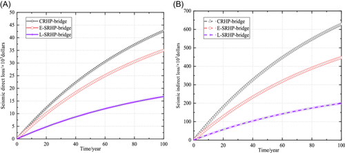
As the service life increases, seismic indirect losses of the three high-speed railway bridges increase. The indirect losses are much greater than the direct losses. Besides, indirect losses reach the maximum when service life is 100 years, and the differences among losses of different bridges are also the largest. The indirect loss of CRHP bridge is 627,620 dollars, whereas the values for E-SRHP and L-SRHP are 447,130.7 dollars and 199,370 dollars, respectively. Seismic indirect loss of the L-SRHP bridge is the minimum, which is 32% of that of the CRHP bridge.
4.2 Life-cycle cost considering seismic loss
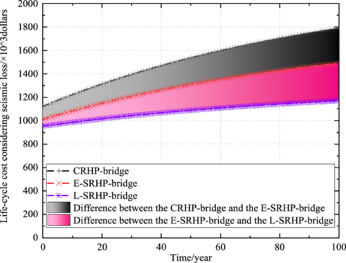
As service time increases, life-cycle costs considering seismic of bridges with CRHP, E-SRHP, and l-SRHP are all increase, and differences in costs among them become increasingly obvious. When the service life of the bridge is 100 years, the life-cycle cost considering the seismic loss of CRHP bridge is 1,792,149.2 dollars, whereas costs of bridges with E-SRHP and L-SRHP are 1,491,791.8 dollars and 1,169,669.2 dollars, respectively. Life-cycle cost considering the seismic loss of the L-SRHP bridge is the minimum, which is only 0.65 times the value of the CRHP bridge. The results indicated that the initial construction costs of bridges with E-SRHP and L-SRHP are less than the cost of CRHP bridge. Furthermore, for the L-SRHP bridge, both the probability of earthquake-induced damage and the repair duration after an earthquake are the minimum compared to the other two bridges.
5 CONCLUSIONS
- 1.
Three high-speed railway bridges equipped with the CRHP, E-SRHP, and L-SRHP were designed, which can serve as references for the designing of bridges with the above three similar piers in future projects.
- 2.
The nonlinear finite element models of the bridge equipped with the SRHP were established and verified by quasi-static tests, which can provide technical assistance for bridge structures with modeling segmentally assembled piers.
- 3.
The results of the seismic fragility analysis revealed that both the E-SRHP and L-SRHP perform better in terms of seismic safety compared to the CRHP bridge in earthquakes due to their good self-centering and energy-dissipation capacities. Furthermore, in terms of moderate damage probability under E3 earthquake, the number of L-SRHP is reduced by 11.96% and 24.3% compared to CRHP and E-SRHP, respectively. This means that L-SRHP possesses the best seismic performance among the three models due to the installation of LPB outside of the pier, which contributes to the faster and better absorption effect of seismic energy, especially in resisting strong earthquakes.
- 4.
A life-cycle seismic loss assessment model for high-speed railway bridges has been established. Based on the characteristics of operation management methods of high-speed railways and their damage repair, a calculation method for transportation loss compensation fee and safety supervision cooperation fee of the bridges is provided, which can function as an alternative tool for evaluating the indirect seismic losses caused by the repairing of earthquake damage in high-speed railway bridge structures.
- 5.
Among the three types of bridges, the L-SRHP bridge possesses the lowest damage probability in earthquakes and features the shortest repairing duration. However, CRHP needs the longest repairing duration, and E-SRHP takes second place. Consequently, the L-SRHP bridge experiences the smallest direct and indirect seismic losses, which are only 39% and 32% of the CRHP bridge. Losses of E-SRHP bridge followed, with 82% and 71% of the CRHP bridge losses, respectively. Besides, for all three types of bridges, the indirect losses are much greater than the direct ones.
- 6.
Regarding life-cycle cost considering seismic loss, the L-SRHP bridge is 17% reduced and the E-SRHP bridge is 35% reduced than that of the CRHP bridge, which indicates that the E-SRHP and L-SRHP bridges can bring superior life-cycle economic benefits.
ACKNOWLEDGMENTS
This study was sponsored by the Project of Science and Technology Research and Development Plan of China Railway Corporation (Grant No. 2015G002-B) and the Key Research and Development Program of Beijing Commission of Science and Technology (Grant No. Z111100074511006).
CONFLICTS OF INTEREST
The authors declare no conflicts of interest.


