Component-level seismic fragility database of suspended piping systems in buildings
Abstract
Nonstructural components (NSCs) contribute about 80%–90% of the construction investment in a modern public building. The post-earthquake safety and normal operation of NSCs are necessary to achieve performance-based design and resilient buildings. The piping system is one of the most essential nonstructural systems to preserve the post-earthquake functionality of public buildings. To accurately evaluate the seismic performance and vulnerability of piping systems in buildings, a component-level seismic fragility database is urgently to be developed. System composition, failure modes of piping systems, and induced consequences during previous earthquakes are introduced first in this article. Then a concise description of component-level fragility methodology suggested by the Applied Technology Council is presented. Seismic fragility database of piping components including pipes, piping joints, and seismic braces through quasi-static tests are developed based on the fragility analysis method. Experimental results from available literature are summarized and presented in the form of seismic fragility curves. Specific hysteretic curves of these components are also presented, which are used for the calibration of numerical models. In addition, the future research directions on the seismic fragility of piping components are summarized and prospected. The developed component-level seismic fragility database can be used to help understand the seismic performance and post-earthquake damage states of the piping system. Seismic performance assessment and seismic fragility analysis of modern piping systems can be conducted using the developed database and numerical simulation method.
1 INTRODUCTION
Nonstructural components (NSCs) are important for functional requirements such as building safety, durability, comfort, and account for most of the total investment in a typical building according to the statistical data of Taghavi and Miranda.1 The investment of NSCs can be up to 80%-90% of the total construction investment. From the perspective of seismic damage after earthquakes, failure of NSCs will lead to the interruption of building functions, huge economic loss, and casualties. And the seismic intensities that induce seismic damage of NSCs are usually smaller than that resulting in heavy damage of structural components (SCs).2-5 In addition, the contribution and effects of NSCs are suggested to be considered in seismic performance assessment with the development of performance-based earthquake engineering (PBEE)6 and seismic resilience assessment of buildings.7, 8
Among the different types of NSCs, a building piping system is one of the most essential nonstructural systems to ensure the functionality of a modern building.9-11 They are used to distribute gas and warm or cold water throughout a building as well as for fire protection purposes when installed with sprinkler heads. A detailed description of building piping components is listed in Table 1 and a diagrammatic drawing of the piping system is shown in Figure 1. After a large earthquake, a pressurized fire sprinkler piping system should operate normally for fire prevention. Operation of the water supply piping system ensures normal domestic water use of the citizens. A medical gas piping system is required for emergency rescue and medical treatment after earthquakes.12-14
| Component | Description |
|---|---|
| Pressure tanks | Pressure tanks provide enough pressure behind the water in a system. |
| Sprinkler heads | Sprinkler heads spray the pressurized water onto an area in case of fire or smoke. |
| Risers | Risers supply water vertically, especially for different floors. Risers and other vertical pipes shall be laterally braced with a riser clamp on each floor. |
| Main runs | Main runs supply water for branch lines horizontally. |
| Branch lines | Branch lines provide water for drop pipes. |
| Drops | Drops are arm-over or straight drops that supply water for the sprinkler head. |
| Vertical Hangers | Vertical Hangers carry the gravity loads of pipes and their contents, e.g., gas or water. |
| Seismic braces | Seismic braces are used to reduce the earthquake-induced deformation and forces of a piping system. |
| Attachment components and anchors | Attachment components and anchors are used to connect vertical hanger rods and braces to the pipe and the supporting structure at the beam or floor slab. |

However, these piping systems are usually sensitive to earthquake inputs and damage of fire sprinkler heads, broken small-diameter piping, fractures of piping joints, failure of vertical hangers and braces, failure of the valve to piping connection, leakage, and water damage,15-26 as illustrated in Figure 2. A statistical percentage data of observed piping systems in a recent earthquake is shown in Figure 3. The seismic damage of piping systems is still significant during large earthquakes and accurate seismic performance assessment and fragility analysis of such system is still needed.


To accurately evaluate the seismic performance and vulnerability of piping systems in buildings, a component-level seismic fragility database is necessary. FEMA P587 provided a component-level fragility database of pipes with different functionality, which can be used in seismic fragility analysis. However, the FEMA P587 database does not distinguish pipe materials, such as black iron pipes, thermoplastic (CPVC) pipes, and steel pipes. The diversity of piping joints (e.g., threaded joints, cement joints, groove-fit joints, etc.) is also not considered. In addition, piping joints are usually displacement-sensitive or deformation-sensitive components while the engineering demand parameter (EDP) provided in FEMA P587 is peak floor acceleration (PFA). The seismic fragility models are usually based on expert experience or from limited post-earthquake data. These deficiencies will lead to inaccurate assessment results in seismic performance assessment. Therefore, it is urgent to build up a new fragility database for components of piping system.
Several researchers have investigated the seismic damage evolution process of pipes and piping joints under increasing amplitude cyclic loading. Antaki and Guzy27 are the first to conduct monotonic loading to investigate the mechanical behavior and seismic damage of threaded, cropper, and grooved piping joints. Cyclic tests were conducted by researchers to investigate the seismic responses of building pipes and piping joints.9, 10, 28, 29 Some studies30-32 have analyzed the mechanical behavior and failure mode of piping braces or brace assemblies. These studies focus on the hysteretic behavior of braces without giving any data to be used for fragility analysis. Fortunately, the seismic tests conducted by Perrone et al.,33 Shang,34 and Shang et al.35 provide useful data to develop a fragility database of piping braces and brace assemblies.
Realizing the shortcomings of the current fragility database for piping components in buildings, this article comprehensively summarizes quasi-static test results of piping components including pipes, piping joints, and piping braces. Experimental seismic fragility models of these piping components from available literature are discussed, summarized, and presented in the form of fragility curves. Specific hysteretic curves of these components are also presented and used in the numerical calibration of piping systems.
2 COMPONENT-LEVEL SEISMIC FRAGILITY METHODOLOGY
For seismic fragility analysis of a considered component, the first step is component damage state definition, followed by a selection of proper EDP. FEMA 35637 defined four damage states for piping systems, i.e., operational (DS1), immediate occupancy (DS2), life safety (DS3), and hazards reduced (DS4), as listed in Table 2. It should be noted that piping and fire sprinkler systems are treated as different systems in FEMA 35637 but descriptions of the damage states are similar (Table 2). HAZUS-MH software package38 also defined four damage states for piping systems, including slight damage (DS1), moderate damage (DS2), extensive damage (DS3), and complete damage (DS4), as listed in Table 2. EDPs may be different for different piping components and systems, e.g., peak ground acceleration (PGA) and PFA are widely used EDPs in system-level fragility analysis. It is noteworthy that provided seismic fragility curves in FEMA 35637 and HAZUS-MH38 adopt PFA as EDP as provided in FEMA P58.7 which is not suitable for component-level seismic performance evaluation of piping systems. Rotation capacity (θ) is used as EDP for piping joints while horizontal displacement (D) is used for piping braces in this article. The next step is to collect the specific EDP values for tested components and conduct log-normal distribution fitting to obtain the fragility parameters. The flowchart of component-level fragility analysis is presented in Figure 4.
| System | Damage state | Description of damage |
|---|---|---|
| Piping systems including fire sprinkler piping systems37 | Operational (DS1) | The seismic damage of the piping system is negligible and has no effect on the normal operation of the system. |
| Immediate Occupancy (DS2) | Minor leakages occur at a few piping joints and have no effects on the normal operation of the system. | |
| Life Safety (DS3) | Minor damages and water leakages occur at a few piping joints, some sprinkler heads are damaged due to swaying of the suspended ceilings and several piping supports are damaged but the pipelines don't fall down. | |
| Hazards Reduced (DS4) | Some sprinkler heads are damaged due to the collapse of the suspended ceilings, water leakages occur at several piping joints, some pipelines rupture, some pipe supports fail and cause pipelines to fall or hang down. | |
| Piping systems38 | Slight damage (DS1) | The seismic damage to the piping system is negligible and has no effect on the normal operation of the system. |
| Moderate damage (DS2) | Piping leaks at a few locations. | |
| Extensive damage (DS3) | Leaks develop at many locations. | |
| Complete damage (DS4) | Pipe is leaking at many locations; some pipe supports have failed causing pipelines to fall or hang down. |

3 DATABASE OF PIPES AND PIPING JOINTS
3.1 Tests by Antaki and Guzy
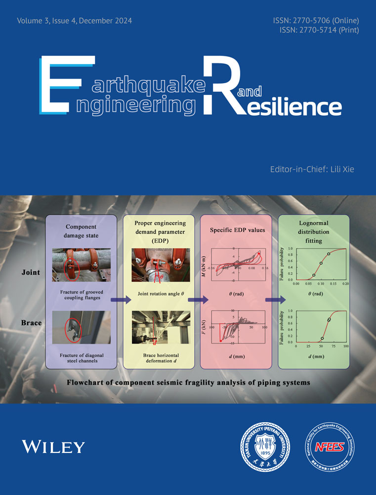
Component-level tests are usually conducted by static tests. Antaki and Guzy27 tested a total of 16 grooved piping joints to investigate the failure mode and leakage-resisting capacity under monotonic loading. The pipes were full of water and pressurized to 1.0 MPa to represent the working state. The piping joints were classified into four sets, i.e., DN100-flexible joints, DN100-rigid joints, DN50-flexible joints, and DN50-rigid joints. DN100 represents that the nominal diameter is 4 in. (100 mm). For each group, four specimens were tested under the same protocol. Fracture of coupling flanges and loss of gasket preload were observed for each grooved piping joint, and the water leakage can be found almost simultaneously. The first leakage point was recorded for each specimen and the calculated fragility parameters of the first leakage is listed in Table 3 for each configuration of piping joints. It can be found from Table 3 and Figure 5 that the rotation angle values at first leakage for the DN50 grooved piping joints were significantly larger than those of the DN100 joints. The rotation capacity will be larger for piping joints with smaller diameters. The deformation ability of flexible joints is usually larger than that of rigid joints with the same diameter and this is determined by their lathedog-plumbings.
| Material and joint type | Photograph | Diameter (mm) | θm (rad) | β |
|---|---|---|---|---|
| DN100-flexible joints | 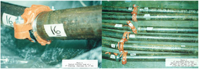 |
100 | 0.0571 | 0.2643 |
| DN100-rigid joints | 100 | 0.0472 | 0.2512 | |
| DN50-flexible joints | 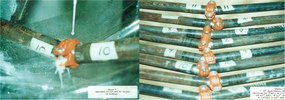 |
50 | 0.1543 | 0.3089 |
| DN50-rigid joints | 50 | 0.1437 | 0.2531 |

3.2 Tests by Tian et al.
Tian et al.9 conducted a series of cyclic tests on different types of piping joints including black iron pipes with threaded joints (BIT), thermoplastic pipes with cement joints (CPVC), and steel pipes with grooved fit joints (GFC), as listed in Table 4. For each type of joint, one monotonic and three cyclic loading tests were conducted. The specimens were full of water and pressurized to 0.28 MPa to simulate the working conditions of pipelines. Both water leakage and fracture of piping joints were observed. Massive water leakage was defined as the damage state for generating seismic fragility curves.
| Material and joint type | Photograph | Diameter (mm) | Wall thicknesses (mm) | θm (rad) | β |
|---|---|---|---|---|---|
| Black Iron with Threaded Joint (BIT) |  |
150 | 7.1 | 0.006 | 0.323 |
| 100 | 6.1 | 0.010 | 0.330 | ||
| 50 | 3.8 | 0.014 | 0.267 | ||
| 25 | 3.3 | 0.031 | 0.290 | ||
| 20 | 2.8 | 0.040 | 0.324 | ||
| CPVC with Cement Joint (CPVC) | 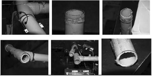 |
50 | 3.8 | 0.088 | 0.274 |
| 25 | 3.3 | 0.148 | 0.252 | ||
| 20 | 2.8 | 0.153 | 0.269 | ||
| Schedule 40 Steel with grooved fit connections (GFC(S40)) | 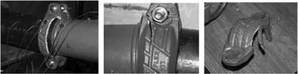 |
100 | 6.1 | 0.021 | 0.255 |
| 50 | 3.8 | 0.077 | 0.302 | ||
| Schedule 10 Steel with grooved fit connections (GFC(S10)) | 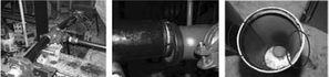 |
100 | 3.3 | 0.079 | 0.271 |
| 50 | 2.8 | 0.059 | 0.270 |
The results indicated that the rotation capacities of the tested piping joints are quite large with a maximum value of 0.405 rad. Based on fragility analysis, the fragility parameters are given in Table 4. It is worth noting that the correction factor 0.25 was not considered by Tian et al.9 but added in Table 4 when calculating logarithmic standard deviation β. It can be found from the seismic fragility curves in Figure 6 that CPVC has the largest rotational capacities at first leakage. For BIT and CPVC with larger diameters, the rotational capacities are smaller. However, the rotation capacities of GFC with different diameters were different. For the thicker schedule 40 steel pipes (GFC(S40) with 6.1 mm wall thickness), the first leakage and fracture damage of the coupling flanges occurred simultaneously. For such damage mode of GFC, the rotational capacities were larger for joints with smaller diameters, e.g., the rotational capacities of DN50 were larger than that of DN100. For the thinner schedule 10 steel pipes (GFC(S10) with 3.3 mm wall thickness), significant inelastic deformations were observed at the piping segments before fracture damage of the coupling flanges. For these piping joints, the rotational capacities increased with pipe diameter.

3.3 Tests by He et al.
He et al.28 conducted cyclic tests on polypropylene-random pipes (PPR) and galvanized steel pipes (GSP) with different diameters, water pressures, wall thicknesses, and loading schemes. The tested pipes were connected by tee joints. A total of 24 sets of water supply pipes were designed and tested based on the cyclic loading protocol suggested by FEMA 461.39 For each set, three cyclic tests were conducted. Both quasi-static tests (0.5–2 mm/s) and dynamic tests (the loading frequency for dynamic tests was set as 1 Hz and the maximum loading rates came up to 50–200 mm/s) were considered to evaluate the effects of loading rates. Fracture of pipes, fracture of tee joints, and pulling-out of pipes were observed for PPR and GSP. The seismic fragility parameters of various types of pipes and piping joints corresponding to leakage damage state were summarized in Table 5.
| Pipe | Photograph | Configuration | Pressure (MPa) | Diameter (mm) | Wall thicknesses (mm) | Loading rate | θm (rad) | β |
|---|---|---|---|---|---|---|---|---|
| PPR | 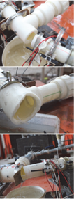 |
PPR-S5 | 0.6 | 40 | 3.7 | S | - | - |
| D | 0.161 | 0.256 | ||||||
| 50 | 4.6 | S | 0.174 | 0.305 | ||||
| D | 0.103 | 0.282 | ||||||
| 75 | 6.8 | S | 0.167 | 0.276 | ||||
| D | 0.070 | 0.297 | ||||||
| 1.0 | 40 | 3.7 | S | - | - | |||
| D | 0.153 | 0.265 | ||||||
| 50 | 4.6 | S | 0.152 | 0.271 | ||||
| D | 0.093 | 0.251 | ||||||
| 75 | 6.8 | S | 0.133 | 0.328 | ||||
| D | 0.078 | 0.288 | ||||||
| PPR-S3.2 | 1.0 | 40 | 5.5 | S | 0.252 | 0.278 | ||
| D | 0.160 | 0.252 | ||||||
| 50 | 6.9 | S | 0.231 | 0.307 | ||||
| D | 0.138 | 0.256 | ||||||
| 75 | 10.3 | S | 0.160 | 0.267 | ||||
| D | 0.068 | 0.255 | ||||||
| GSP | 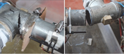 |
1.0 | 32 | 3.5 | S | 0.018 | 0.278 | |
| D | 0.020 | 0.323 | ||||||
| 40 | 3.5 | S | 0.013 | 0.264 | ||||
| D | 0.022 | 0.295 | ||||||
| 65 | 4.0 | S | 0.011 | 0.273 | ||||
| D | 0.021 | 0.277 | ||||||
- Note: S represents quasi-static tests, while D represents dynamic tests.
Fragility curves of different pipes and piping joints are presented in Figure 7. For PPR and GSP pipes with larger diameters, the rotation angle values corresponding to first leakage are smaller. For PPR pipes with the same diameter, the rotational capacities varied for different loading modes, specifically, the rotational capacity was smaller for dynamic tests compared with quasi-static tests. However, the rotational capacity of GSP was larger for dynamic tests compared with quasi-static tests. It can also be found that the rotational capacity of PPR decreased with an increase in water pressure and wall thickness.

3.4 Tests by Wang et al.
The diameters of GFC piping joints tested by Tian et al.9 were less than 100 mm. However, some public buildings often select large-diameter pipes, e.g., with a diameter of 150 mm for fire sprinkler piping systems. Wang et al.29 investigated the seismic responses and damage modes of grooved fit piping joints with large diameters including DN80 and DN150. Three types of grooved fit joints are considered, i.e., elbow joint connected by DN150 piping segments (10 mm wall thicknesses), tee joint connected by DN150 piping segments (10 mm wall thicknesses), and tee joint connected by DN80 piping segments (5 mm wall thicknesses). The grooved fit piping joints were connected to the galvanized steel pipe segments for seismic tests. The test piping specimens were filled with water with a pressure of 1.6 MPa to simulate the real working condition of such fire sprinkler piping systems. Similar to tests by Tian et al.,9 one monotonic and three cyclic loading tests were conducted for the three joint sets per FEMA 46139 loading protocol. Fracture of coupling flanges connected to DN150 piping segments and the pulling-out of DN80 piping segments were observed as the main seismic damage of the tested specimens. Both of the two damage modes will result in massive water leakage and loss of functionality. Wang et al.29 defined three damage states for grooved fit joints based on the observed damage during the cyclic loading process, i.e., DS1 reflects water pressure inside the pipeline drops to 85% of the initial pressure, DS2 represents massive water leakage and there exists no pressure inside the pipeline, while DS3 is completely mechanical failure of the piping joint specimen. The calculated seismic fragility parameters are listed in Table 6.
| Joint type | Pressure (MPa) | Wall thicknesses (mm) | Damage state | θm (rad) | β | Photograph |
|---|---|---|---|---|---|---|
| Elbow | 1.6 | 10 | 0.033 | 0.256 |  |
|
| 1.6 | 10 | 0.064 | 0.313 | |||
| 1.6 | 10 | 0.096 | 0.398 | |||
| DN150 tee joint | 1.6 | 10 | 0.057 | 0.285 | 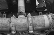 |
|
| 1.6 | 10 | 0.089 | 0.291 | |||
| 1.6 | 10 | 0.12 | 0.269 | |||
| DN80 tee joint | 1.6 | 5 | 0.173 | 0.253 |  |
|
| 1.6 | 5 | 0.217 | 0.259 | |||
| 1.6 | 5 | 0.299 | 0.254 |
Considering that the water leakage is the damage state directly associated with functionality loss, a comparison of seismic fragility curves corresponding to the water leakage damage state (DS2) was depicted in Figure 8. The rotational capacity of the DN80 tee joint is the largest among the three types of grooved fit piping joints tested by Wang et al.29 The fragility curves are further compared with grooved fit piping joints tested by Tian et al.9 in Figure 8. The comparison results indicated that the rotation capacities of DN150 and DN80 tested by Wang et al.29 are larger than that of GFC4"(S40)-DN100 and GFC2"(S40)-DN80 tested by Tian et al.9 However, it should be noted that more test data are still needed to further consider the effects of different pipeline size and joint configuration.

Based on the test results from Tian et al.,9 the rotational capacities of BIT and CPVC piping joints under monotonic tests are larger than those under cyclic loading, which indicates that loading protocol may have a great influence on the rotational capacities. Similar trends were observed for grooved fit piping joints tested by Wang et al.29 Such results demonstrate that small seismic inputs, e.g., small deformations during repeated cyclic loading may reduce the deformation capacity of such piping joints. The deformation capacities of these piping joints may degenerate under several rounds of small seismic inputs and therefore result in loss of seismic resistance under huge earthquakes.
3.5 Tests by Blasi et al.
Blasi et al.10 performed quasi-static cyclic tests based on the FEMA 46139 loading protocol to evaluate the seismic responses of cast-iron steel pipes with threaded joints (CSP-TJ, fire-protection piping systems) and copper pipes with welded joints (CP-WJ, medical gas piping systems). Leakage at the pipe-joint interface was observed accompanied with loss of pressure inside the pipeline and the rotation angles corresponding to the leakage were adopted to generate seismic fragility models. A summary of the specimens tested is provided in Table 7. For CSP-TJ, the results of five cyclic tests and one monotonic test are used for fragility analysis and the specimens were filled with water and pressurized to 0.2 MPa, while for CP-WJ, the results of two cyclic tests and one monotonic test are used for fragility analysis and the pipes were filled with air and pressurized to 0.4 MPa. It is noteworthy that monotonic test results are included to generate fragility curves (Figure 9) and consider the variety of specimens. It can be found from Figure 9 that the rotational capacity of CP-WJ is much larger than that of CSP-TJ. From comparison between the fragility curves of CSP-TJ and BIT2" in Tian et al.9 (diameter is 50 mm, wall thickness is 3.8 mm, water pressure is 0.28 MPa) demonstrates that BIT2" (θm is 0.014 rad) may be more vulnerable than CSP-TJ (θm is 0.0326 rad) although the pipes and joints are in similar configurations. The results indicate that piping systems designed following different design codes may have quite different seismic performance.
| Joint type | Pressure (MPa) | Diameter (mm) | Wall thicknesses (mm) | θm (rad) | β | Photograph |
|---|---|---|---|---|---|---|
| CSP-TJ | 0.2 | 60 | 3.2 | 0.0326 | 0.2636 | 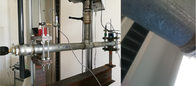 |
| CP-WJ | 0.4 | 55 | 1.5 | 0.2085 | 0.2666 | 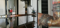 |

3.6 Comparison of piping joint seismic performance
Piping joint tests usually select the piping segment connected by corresponding piping joints as the specimen to investigate piping joint performance from the perspective of rotation capacity before leakage, maximum rotation capacity, moment capacity, seismic damage mode, and component-level seismic fragilities. The main damage or failure modes of the tested piping joint specimens are usually pulled out of the piping segment from the piping joint, fracture of the piping segment, and failure of the piping joint (e.g., fracture of coupling flange, fracture of the piping joint itself). All of these damages will result in loss of piping inside pressure and massive water leakage, which means the functionality of the pipeline will be lost. In addition, some slight damage including degeneration of thread sealant, wear of piping segment, and deformation of the piping segment were also observed during the loading process.
Based on the test results of piping joints, it was found that the rotation capacity may be quite different for piping joints made up of different materials and configurations. The DN150 (from 0.054 to 0.123 rad) and DN80 (from 0.202 to 0.274 rad) grooved piping joints tested by Wang et al.29 exhibit large rotational capacities ranging before massive leakage, which are quite larger than that of America-style grooved piping joints (from 0.0199 to 0.0921 rad for DN100, from 0.0546 to 0.0748 rad for DN80) tested by Tian et al.9 Such differences can also be found for BITs (from 0.0125 to 0.0151 rad for BIT2") tested by Tian et al.9 may be more vulnerable than cast-iron steel pipes with threaded joints (from 0.031 to 0.033 rad for CSP-TJ) tested by Blasi et al.10 although the pipes and joints are in similar configurations and sizes. Matsubara et al.40 suggested that to prevent water leakage and deterioration in the bearing strength of carbon steel pipe with threaded joints, the plastic rotation angle must be kept below 0.03 rad regardless of the diameter of the pipes. Actually, the rotation capacities before any water leakage are 0.047, 0.046, 0.049, and 0.032 rad for 34.0-, 48.6-, 60.5- and 89.1-mm specimens tested by Matsubara et al.,40 which are almost twice than the 0.0334, 0.0275, 0.0125, 0.0087, and 0.0051 rad rotation capacities for 19.05-, 25.4-, 50.8-, 101.6-, and 152.4-mm BITs tested by Tian et al.9 These results indicates that piping systems designed following different design codes may have quite different seismic performance.
The component size will significantly affect the rotation capacity of piping joints based on these test results. In general, the rotation capacity will be larger for piping joints with smaller diameters. This rule was proved by test results of grooved piping joints by Antaki and Guzy,27 BIT and CPVC by Tian et al.,9 PPR and GSP by He et al.,28 and carbon steel pipe with threaded joints by Matsubara et al.40 It should be noted that these tests all follow a damage mode of piping joint failure first and the water leakage occurred simultaneously. However, the trend will be different if other failure modes occurred, e.g., Tian et al.9 found that for pipes with smaller diameters, the piping segment itself will suffer from obvious deformation before seismic damage to the piping joints. Such pipe deformation will result in a large rotation before water leakage.
4 DATABASE OF PIPING BRACES
4.1 Tests by Perrone et al.
Perrone et al.33 conducted seismic tests on piping brace assemblies including both monotonic and cyclic loading per FEMA 46139 loading protocol. Four types of piping seismic brace assemblies were tested, i.e., SS1-SS4 shown in Table 8. The differences between these specimens include the loading direction (e.g., loaded along the transverse or longitudinal direction), and diagonal brace types (e.g., using steel channels or threaded rods as diagonal braces). It should be noted that the transverse direction represents the direction perpendicular to the pipeline direction, while the longitudinal direction is the direction along the pipeline direction. Two damage states were identified for piping brace assemblies based on the test results. DS1 represents slight damage which has no effects on piping system functionality and can be repaired easily. DS2 represents heavy damage to the piping brace assemblies but such damage will not threaten the life safety of inside occupants. For seismic fragility analysis of piping braces, the displacement of the braces was selected as EDP parameters and the median value is denoted as dm. The effective yield displacement is used to define DS1 while the ultimate deformation is used to define DS2 to generate conservative fragility curves. Fragility parameters are listed in Table 8 and Figure 10 shows the generated seismic fragility curves. The displacement demand of piping brace assemblies loaded in the transverse direction is found to be larger than that loaded in the longitudinal direction. And the piping brace assemblies using steel channels as diagonal braces are with larger stiffness compared with those using threaded rods as diagonal braces.
| Brace type | Loading direction | DS1 | DS2 | Photograph | ||
|---|---|---|---|---|---|---|
| dm | β | dm | β | |||
| SS1 | Transverse | 13.10 | 0.2649 | 24.68 | 0.2912 | 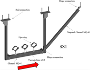 |
| SS2 | Longitudinal | 17.25 | 0.2677 | 52.36 | 0.3588 | 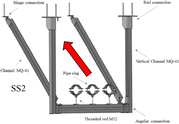 |
| SS3 | Transverse | 5.43 | 0.2924 | 18.99 | 0.3972 | 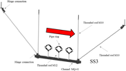 |
| SS4 | Longitudinal | 13.83 | 0.3244 | 54.45 | 0.3302 | 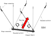 |

4.2 Tests by Shang
Shang34 evaluated the seismic performance of longitudinal and transverse combination braces (LTCBs) per FEMA 46139 loading protocol. Both LTCBs with 12 mm vertical hanger rod (M12) and LTCBs with 16 mm vertical hanger rod (M16) were tested and the effects of hanger diameter were investigated. The specimen geometry was chosen to reasonably represent an average brace system found in practice. The diagonal braces extend out on a typical 45° for an extra depth of 800 mm. The load was applied perpendicularly to the hanger rod. Failure of the specimen was first observed through the rotation of the lower attachment located at the bottom of the hanger rod and yielding through bending of the threaded rods (DS1). The final seismic damage was concentrated at the channel strut, which suffered significant strut crushing (DS2). It is noteworthy that the EDP values for DS1 (yield displacement) and DS2 (ultimate deformation) are all obtained from the hysteretic curves. Complete damage happened in the negative loading direction when the contact surface between the channel strut and pre-tightening bolt suffered tension failure gradually. The displacements of M12 braces are much larger than those of M16 braces because 12 mm hanger rod is more flexible than 16 mm hanger rod. The experimental fragility models for LTCBs are presented in Table 9 and Figure 11. The displacements corresponding to an exceedance probability of 50% are 48 and 60 mm for M16 and M12 braces, respectively. M12 braces are more flexible and have a larger deformation capacity which means that the pounding possibility between suspended pipelines supported by M12 braces with surrounding structural members and NSCs may be larger than that supported by M16 braces.
| Brace type | DS1 | DS2 | Photograph | ||
|---|---|---|---|---|---|
| dm | β | dm | β | ||
| M12 | 12.95 | 0.2881 | 60.35 | 0.2841 | 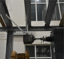  |
| M16 | 12.58 | 0.2542 | 48.00 | 0.2740 | |

4.3 Tests by Shang et al.
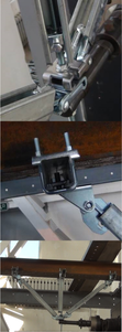
Shang et al.35 conducted seismic tests on seismic braces with different configurations per FM195041 loading protocol. The differences between tested seismic braces lie in the diagonal brace types and bottom-top connection components, as shown in Table 10. The damage state is considered to be achieved if the horizontal deformation of the tested seismic brace exceeds 50 mm specified by FM195041 or the brace loses earthquake resistance capacity before 50 mm deformation. The ultimate bearing strength values corresponding to the defined damage state were identified from the force-displacement hysteretic curves and further transformed to PFA values considering an average mass distribution of the supported 12 m pipelines. The seismic fragility analysis results are shown in Table 10 and Figure 12. The threaded rod brace using steel channels as diagonal braces was identified as the most robust one among the tested braces. It should also be noted that such type braces are also the one most widely used in engineering. In addition, it is worth noting that the FM195041 loading protocol is force-controlled which is different from the FEMA 46139 loading protocol, the displacement-controlled one. As pointed out by Filiatrault et al.,32 the FM195041 loading protocol will dissipate more seismic energy than FEMA 46139 under similar deformation values, which could result in unrealistic seismic damage of piping braces which are rarely observed in real earthquakes, e.g., fatigue failure of brace components. And the loading rate of FM195041 is also much lower than that of FEMA 461,39 which cannot represent the real characteristics of earthquakes. Filiatrault et al.32 suggested to use FEMA 46139 loading protocol in seismic performance tests of piping seismic braces. A detailed comparison of different loading protocols for seismic performance tests of piping components can be found in Filiatrault et al.32 Therefore, the results of Table 10 and Figure 12 may provide nonconservative estimation of piping brace capacity.
| Brace type | Steel wire brace | Beam clamp brace | Threaded rod brace |
|---|---|---|---|
| Photograph | 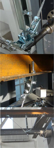 |
 |
 |
| PFAm | 1.98 | 2.23 | 3.20 |
| β | 0.396 | 0.371 | 0.525 |

4.4 Tests by Shang et al.
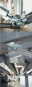
Shang et al.42 conducted component-level tests on 12 seismic sway braces of suspended piping system per FM195041 loading protocol. The tested seismic sway braces all adopt steel channel struts as diagonal braces. The specimen configurations are different in installation height, installation angles, and numbers of diagonal braces. Shang et al.42 found that the number of diagonal brace elements of tested specimens will significantly affect the seismic brace performance. Their cyclic test results indicate that adding one diagonal brace can significantly increase the bearing strength and energy dissipation capacity of seismic sway braces and delay the time of failure by increasing the deformation capacity before failure. The braces with double diagonal channels showed higher stiffnesses and larger bearing strengths than those with single diagonal channel. Based on the test results, two damage states are defined for seismic sway braces, namely the Serviceability Limit State (SLS) and Ultimate Limit State (ULS). SLS was defined for the seismic performance that NSCs may show minor damage, but the damage could be economically repaired and does not affect the functionality of the building, e.g., minor yielding or elastic buckling in some components of seismic sway braces. ULS was defined for the seismic performance that NSCs can be damaged, but without compromising life-safety, e.g., seismic sway braces are damaged but the hangers still hold the pipes. The EDP value is determined as the displacement corresponding to 40% of the maximum load for SLS, while that for ULS was determined as the displacement corresponding to the complete failure of the NSCs or maximum recorded displacement during the test or 50 mm, whichever was smaller. The corresponding seismic fragility parameters and generated fragility curves are listed in Table 11 and Figure 13.
| Brace type | 500-1-SLS | 500-1-ULS | 1000-1-SLS | 1000-1-ULS | Photograph |
|---|---|---|---|---|---|
| dm | 5.14 | 45.27 | 8.42 | 49.95 | 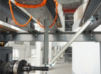 |
| β | 0.1161 | 0.1495 | 0.3436 | 0.0010 | |
| Brace type | 500-2-SLS | 500-2-ULS | 1000-2-SLS | 1000-2-ULS | Photograph |
| dm | 10.56 | 46.35 | 10.74 | 48.15 | 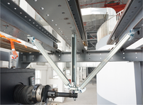 |
| β | 0.5166 | 0.0964 | 0.2140 | 0.0602 |
- Note: Brace type 500-1 represents the seismic sway braces adopting one diagonal channel with an installation height of 500 mm.

4.5 Comparison of seismic brace performance
For tests of piping braces or brace assemblies, the loading direction of seismic braces was found to have a great influence on their seismic performance. Perrone et al.33 reported that the displacement demand of seismic braces loaded in the transverse direction is larger than that loaded in the longitudinal direction, which indicates that the transverse direction is the weaker direction with large displacement demand, which may have a higher probability to exceed the displacement threshold value (e.g., 50 mm in FM195041) or suffer pounding damage with surrounding SCs and NSCs. The test results on seismic braces using vertical hanger rods with different diameters by Shang34 indicate that the flexibility of vertical hanger rods will also induce high displacement demand on the supported piping systems.
The piping brace assemblies using threaded rods as diagonal brace elements are much more vulnerable than those using steel channels as diagonal braces33 if a deformation threshold damage state is considered to avoid possible pounding response with surrounding components. In addition, the test results from different research31, 43, 44 all indicate that the connectors or joints which connect the diagonal brace elements to the floor slab will significantly affect the hysteretic force-displacement responses of seismic braces. Adding one diagonal channel was found can considerably improve the seismic performance of seismic sway braces.42 Therefore, it is suggested to consider the distribution of diagonal braces economically and seismic efficiently when designing the supporting system of suspended building piping systems.
5 HYSTERETIC CURVES AND NUMERICAL SIMULATION OF TESTED PIPING COMPONENTS
5.1 Hysteretic curves of tested piping components
Typical hysteretic curves of different piping joints and braces obtained from cyclic tests mentioned above are summarized in this article. As shown in Figure 14, the moment-rotation hysteretic curves are multifarious for piping joints with different configurations from different tests, which further demonstrates the importance of distinguishing different piping components in seismic fragility analysis. It can be found from Figure 15 that the force-displacement hysteretic curves for different piping braces are also different. Therefore, the seismic performance of these piping components may be quite different even under the same seismic inputs. Although the above-mentioned seismic fragility model database can be directly used in component-level seismic fragility analysis of piping systems once the system configuration is given, a detailed seismic dynamic responses evaluation of piping components still relies on accurate numerical simulation of the dynamic behavior under earthquakes. By using reliable numerical modeling methods, a more comprehensive seismic fragility assessment of piping systems can be achieved.


5.2 Numerical simulation of tested piping components
Typical hysteretic curves of different piping joints and braces obtained from the cyclic tests mentioned above can be used for the calibration of numerical models for piping components. The main considered components in piping system simulation include piping joints, piping segments, vertical hanger rods, and piping seismic braces, as presented in Figure 16. Component hysteretic response simulations of piping systems are usually conducted by simplified spring-based models accompanied with uniaxial hysteresis material constitutive. The OpenSees software is usually selected as the finite element platform due to its high computational efficiency and variety of material models. The Pinching4 material in OpenSees has been widely adopted to simulate the hysteretic responses of piping components, e.g., moment-rotation responses of piping joint connections and horizontal force-displacement responses of seismic braces for pipes. A brief introduction of the Pinching4 material in OpenSees can be found in Figure A1 of Appendix A. The piping segments are usually simulated by beam elements considering either linear behavior properties or nonlinear behavior properties by fiber sections. The nonlinear behavior of vertical hangers can be simulated by beam elements with inelastic fiber section properties. It should be noted that the axial performance of the vertical hanger can also be simulated by an axial spring with the zero-length element model.


To demonstrate the accuracy of the above-mentioned numerical simulation method for piping components, the test results from Tian et al.,9 Blasi et al.,10 Perrone et al.,33 and Shang et al.42 were selected and numerical models of these components were developed in OpenSees. The calibrated Pinching4 material parameters are listed in Tables A1 and A2 of Appendix A. Comparisons between the numerical simulation results and test results of piping joints and seismic braces are also presented in Figures 14 and 15. The numerical simulation hysteresis responses match very well with the experimental curves, which indicates that the developed numerical models can accurately reproduce the hysteresis responses of both piping joints and seismic braces. In addition, the accuracy and effectiveness of the numerical model in system-level seismic analysis have been proved in a previously published work by the authors11 and these analysis results are omitted here due to space limitation.
One example of the application of the hysteretic curves and fragility database is described by Soroushian et al.45, 46 In their studies, piping segments are modeled using beam elements with elastic section properties, while the piping joints are modeled by zero-length elements with nonlinear Pinching4 material based on the hysteretic behavior obtained from cyclic tests. Steel02 material is used for the simulation of the inelastic behavior of vertical hangers by beam elements. Elastic section properties are adopted for beam elements to simulate piping braces, while this may differ from the real behavior of piping braces. Soroushian et al.45, 46 conducted fragility analyses for both the component level and system level using nonlinear time history analysis (NTHA) results and the component-level seismic fragility models.
6 SUMMARY AND DISCUSSION
- 1.
Damages of piping joints were widely found in seismic tests and such damage will result in massive water leakage. The component size will significantly affect the rotation capacity of piping joints. The rotation capacity will be larger for piping joints with smaller diameters when the specimens follow a damage mode of piping joint failure first and the water leakage occurs simultaneously.
- 2.
The rotational capacities for black iron pipes with threaded joints, thermoplastic pipes with cement joints, and large diameter grooved fit piping joints under monotonic loading are usually larger than those under cyclic loading. The deformation capacities of these piping joints may degenerate under several rounds of small seismic inputs and therefore result in loss of seismic resistance under huge earthquakes.
- 3.
The loading direction of seismic braces will have a great influence on their seismic responses. Typically, the displacement demand of seismic braces loaded in the transverse direction is larger than that loaded in the longitudinal direction, which indicates that the transverse direction is the weaker direction with a large displacement demand. The pounding probability between suspended pipelines in the brace transverse direction with surrounding structural members and nonstructural components may be larger than the longitudinal direction.
- 4.
The flexibility of vertical hanger rods will also induce high displacement demand on seismic braces. The piping braces using steel channels as diagonal braces are with larger stiffness compared with those using threaded rods as diagonal braces. In addition, increasing the number of diagonal braces can efficiently improve the seismic performance of seismic braces. The connectors or joints that connect the diagonal brace elements to the floor slab may also affect the hysteretic behavior of seismic braces.
The developed seismic database can be used to help understand the seismic performance and post-earthquake damage states of piping systems from the component level. Specific hysteretic curves of these components can be adopted to calibrate numerical models of piping systems. Based on the calibrated numerical models and component-level seismic fragility database, nonlinear time history analysis can be conducted to evaluate the seismic fragility of suspended piping systems.
- 1.
The seismic performance can be quite different for piping components with even similar materials and configurations. This may be the result of different design codes and manufacturing techniques in different countries. Therefore, more tests on piping components still need to be conducted and selected to enrich and enlarge the developed database.
- 2.
The dynamic seismic responses of suspended piping systems in a building rely on different factors, e.g., the piping segment may suffer from buckling damage and change the system configurations. The influence of piping segment length still needs to be further investigated.
- 3.
Another important factor that affects the dynamic seismic responses of suspended piping systems is the floor acceleration, which usually amplifies the ground inputs through the supporting structures. The component-level quasi-static cyclic tests presented in this study didn't consider the dynamic effect of actual earthquakes, which can be investigated by large-scale shaking table tests or numerical simulations based on the proposed models.
- 4.
The considered piping components mainly include piping segments, piping joints, and piping seismic braces. Some other mechanical components of piping systems in buildings, e.g., pressure tanks and sprinkler heads are not considered in this study. The corresponding seismic fragility models still need to be developed.
- 5.
Apart from the seismic damage definition and fragility models developed in this study, the post-earthquake repair method and repair cost of these components are also important and should be considered in future studies.
ACKNOWLEDGMENTS
This research was funded by the National Natural Science Foundation of China (52208483) and the National Science Foundation for Distinguished Young Scholars (52125806).
CONFLICTS OF INTEREST
The authors declare no conflicts of interest.
APPENDIX A
A schematic diagram of the Pinching4 uniaxial material and the corresponding parameters defining the hysteretic rules in OpenSees is presented in Figure A1. A total of 39 parameters are adopted for the material definition. The definition of Pinching4 uniaxial material includes skeleton curve, unloading-reloading path, unloading, reloading stiffness degradation, and strength degradation criteria. The solid line in Figure A1 shows the skeleton curve while the dotted line demonstrates the unloading-reloading path under cyclic loading. Detailed descriptions of the 39 parameters used to define the hysteresis behavior can be found at the Website of OpenSees (https://opensees.berkeley.edu/wiki/index.php?title=Pinching4_Material).
| Parameter | BIT-1 in-Specimen 3-Left | BIT-2 in-Specimen 2-Left | BIT-4 in -Specimen 3-Left | Joint-FCT 1 | Joint-FCT 3 | Joint-MCT 2 |
|---|---|---|---|---|---|---|
| ePf1 | 1.5 | 15 | 60 | 1.45 | 1.0 | 0.2263 |
| ePf2 | 3.34 | 22 | 130 | 1.81 | 1.5 | 0.4971 |
| ePf3 | 4.3 | 24 | 131 | 0.0106 | 0.0091 | 0.0094 |
| ePf4 | 3.0 | 24.34 | 125 | 0.0286 | 0.0245 | 0.0551 |
| ePd1 | 0.001 | 0.001 | 0.001 | 1.63 | 1.25 | 0.0580 |
| ePd2 | 0.008 | 0.003 | 0.003 | 0.362 | 0.3 | 0.3634 |
| ePd3 | 0.025 | 0.01 | 0.013 | 0.0196 | 0.0168 | 0.0216 |
| ePd4 | 0.03 | 0.023 | 0.013 | 0.0330 | 0.0350 | 0.1595 |
| eNf1 | −1.5 | −8 | −60 | −1.45 | −1.000 | −0.226 |
| eNf2 | −6.1 | −13.5 | −105 | −1.81 | −1.5 | −0.4971 |
| eNf3 | −7.45 | −18 | −115 | −0.0106 | −0.0091 | −0.0094 |
| eNf4 | −5.0 | −19.5 | −116 | −0.0286 | −0.0245 | −0.0551 |
| eNd1 | −0.001 | −0.001 | −0.001 | −1.63 | −1.25 | −0.058 |
| eNd2 | −0.005 | −0.005 | −0.004 | −0.362 | −0.3 | −0.3634 |
| eNd3 | −0.02 | −0.01 | −0.01 | −0.0196 | −0.0168 | −0.0216 |
| eNd4 | −0.035 | −0.023 | −0.02 | −0.0330 | −0.0350 | −0.1595 |
| rDispP | 0.2 | 0.1 | 0.4 | 0.3 | 0.3 | 0.0 |
| rForceP | 0.5 | 0.4 | 0.001 | 0.1 | 0.1 | 0.95 |
| uForceP | −0.5 | 0.01 | 0.0001 | 0 | 0 | 0.2 |
| rDispN | 0.2 | 0.1 | −0.2 | 0.3 | 0.3 | 0.0 |
| rForceN | 0.8 | −0.1 | 0.15 | 0.1 | 0.1 | 0.95 |
| uForceN | 0.0001 | −0.25 | 0.0001 | 0.0 | 0.0 | 0.2 |
| gK1 | 0.5 | 0.7 | 0.6 | 0.0 | 0.0 | 0.5 |
| gK2 | 0.5 | 0.7 | 0.6 | 0.0 | 0.0 | 0.5 |
| gK3 | 0.5 | 0.7 | 0.6 | 0.0 | 0.0 | 1.0 |
| gK4 | 0.5 | 0.7 | 0.6 | 0.0 | 0.0 | 1.0 |
| gKLim | 0.5 | 0.7 | 0.6 | 0.0 | 0.0 | 0.35 |
| gD1 | 0.0 | 0.0 | 0.0 | 0.5 | 0.5 | 0.02 |
| gD2 | 0.0 | 0.0 | 0.0 | 0.5 | 0.5 | 0.02 |
| gD3 | 0.0 | 0.0 | 0.0 | 0.1 | 0.1 | 1.0 |
| gD4 | 0.0 | 0.0 | 0.0 | 0.1 | 0.1 | 1.0 |
| gDLim | 0.0 | 0.0 | 0.0 | 0.04 | 0.04 | 0.05 |
| gF1 | 0.0 | 0.0 | 0.0 | 0.0 | 0.0 | 4.0 |
| gF2 | 0.0 | 0.0 | 0.0 | 0.0 | 0.0 | −1.5 |
| gF3 | 0.0 | 0.0 | 0.0 | 0.0 | 0.0 | 1.0 |
| gF4 | 0.0 | 0.0 | 0.0 | 0.0 | 0.0 | 0.01 |
| gFLim | 0.0 | 0.0 | 0.0 | 0.0 | 0.0 | 0.15 |
| gE | 1.0 | 1.0 | 1.0 | 1.0 | 1.0 | 1.0 |
| dmgType | cycle | cycle | cycle | cycle | cycle | cycle |
| Parameter | SS2-a | SS3-a | SS4-a | 1000-30-2 | 1000-45-2 | 1000-60-2 |
|---|---|---|---|---|---|---|
| ePf1 | 1.2 | 1.6 | 0.8 | 3.7 | 8.2 | 9.9 |
| ePf2 | 15.0 | 11.6 | 17.0 | 6.8 | 15.3 | 18.2 |
| ePf3 | 20.0 | 8.0 | 22.0 | 9.2 | 20.6 | 24.8 |
| ePf4 | 19.0 | 7.0 | 13.0 | 1.9 | 4.1 | 5.0 |
| ePd1 | 0.1 | 0.1 | 0.1 | 8.4 | 12.4 | 11.9 |
| ePd2 | 12.0 | 9.3 | 14.0 | 20.1 | 24.3 | 25.0 |
| ePd3 | 24.0 | 30.0 | 36.0 | 41.5 | 49.6 | 44.7 |
| ePd4 | 61.0 | 78.0 | 85.0 | 60.0 | 60.0 | 60.0 |
| eNf1 | −1.2 | −1.6 | −0.8 | −3.7 | −8.2 | −9.9 |
| eNf2 | −15.0 | −12.6 | −14.0 | −6.8 | −15.3 | −18.2 |
| eNf3 | −20.0 | −7.6 | −18.0 | −9.2 | −20.6 | −24.8 |
| eNf4 | −27.0 | −7.0 | −14.0 | −1.9 | −4.1 | −5.0 |
| eNd1 | −0.1 | −0.1 | −0.1 | −8.4 | −12.4 | −11.9 |
| eNd2 | −12.0 | −9.3 | −12.0 | −20.1 | −24.3 | −25.0 |
| eNd3 | −24.0 | −30.0 | −36.0 | −41.5 | −49.6 | −44.7 |
| eNd4 | −60.0 | −78.0 | −85.0 | −60.0 | −60.0 | −60.0 |
| rDispP | 0.1 | 0.3 | 0.5 | 0.8 | 0.8 | 0.8 |
| rForceP | 0.45 | 0.6 | 0.85 | 0.05 | 0.05 | 0.05 |
| uForceP | −0.2 | −0.7 | −0.7 | −0.01 | −0.01 | −0.01 |
| rDispN | 0.4 | 0.4 | 0.4 | 0.8 | 0.8 | 0.8 |
| rForceN | 0.55 | 0.4 | 0.85 | 0.05 | 0.05 | 0.05 |
| uForceN | −0.2 | −0.8 | −0.4 | −0.01 | −0.01 | −0.01 |
| gK1 | 0.75 | 0.5 | 0.4 | −0.2 | −0.2 | −0.2 |
| gK2 | 0.0 | 0.0 | 0.3 | −0.2 | −0.2 | −0.2 |
| gK3 | 0.0 | 0.0 | 0.3 | −0.2 | −0.2 | −0.2 |
| gK4 | 0.6 | 0.0 | 0.2 | −0.2 | −0.2 | −0.2 |
| gKLim | 0.75 | 0.9 | 0.9 | −2 | −2 | −2 |
| gD1 | 0.7 | 0.0 | 0.0 | −0.5 | −0.5 | −0.5 |
| gD2 | 0.0 | 0.0 | 0.0 | −0.5 | −0.5 | −0.5 |
| gD3 | 0.0 | 0.0 | 0.0 | −0.5 | −0.5 | −0.5 |
| gD4 | 0.6 | 0.0 | 0.0 | −0.5 | −0.5 | −0.5 |
| gDLim | 0.05 | 0.0 | 0.0 | −0.5 | −0.5 | −0.5 |
| gF1 | 0.0 | 0.0 | 0.0 | 0.0 | 0.0 | 0.0 |
| gF2 | 0.0 | 0.0 | 0.0 | 0.0 | 0.0 | 0.0 |
| gF3 | 0.0 | 0.0 | 0.0 | 0.0 | 0.0 | 0.0 |
| gF4 | 0.0 | 0.0 | 0.0 | 0.0 | 0.0 | 0.0 |
| gFLim | 0.0 | 0.0 | 0.0 | 0.0 | 0.0 | 0.0 |
| gE | 10.0 | 10.0 | 10.0 | 1.0 | 1.0 | 1.0 |
| dmgType | cycle | cycle | cycle | cycle | cycle | cycle |