3D Printed Microreactors for the Continuous Non-Kolbe Electrolysis
Abstract
In the renaissance of organic electrochemistry, 150-year-old Kolbe chemistry offers a sustainable pathway to liquid energy carriers and commodities. Herein, easy-access design methods for electrochemical microreactors employing 3D printing and simple post processing techniques are presented. The continuous Non-Kolbe electrolysis of monomethyl succinic acid is studied as a test reaction for the production of an industrially relevant, green monomer. In a semi-batch setup, methyl acrylate is produced with a maximum yield of 34 %, similar to results from a thoroughly optimized batch reaction in a prior study. In single-pass experiments, a comparable faradaic efficiency of 54 % is achieved.
1 Introduction
Renewable energy like solar and wind power is increasingly available 1. To make these fluctuating sources dispatchable, a decentral, adaptive, and flexible energy use becomes indispensable. Electrosynthesis represents a key technology to achieve this, by storing green electrons in liquid energy carriers or valuable commodities. In this context, the interest in (Non-)Kolbe electrolysis has grown in recent years 2. The opportunity to convert carboxylic acids, a major fraction available by transforming lignocellulosic biomass, into monomers 3, liquid fuels 4, 5, or fine chemicals 6 combines the use of green energy with the vision of a circular carbon economy. The versatility of the (Non-)Kolbe electrolysis – also called anodic decarboxylation – originates from its reaction mechanism (see Fig. S6 in the Supporting Information SI) 7, 8. Following the Kolbe radical pathway, a recombination of alkyl species enables chain prolongation. Recent studies show potential applications for alkanes from (cross-)coupling 5, 9, second generation platform molecules 10, 11, and (bifunctional) monomers synthesized from di-acids 3, 12. The cationic Non-Kolbe pathway is opened by a consecutive oxidation of the Kolbe radical. It provides access to nitrogen- or oxygen-functionalized molecules via the reaction with a nucleophile or molecules possessing a terminal double bond formed through deprotonation. These olefins include important monomers like propylene 12, 13 or ethyl acrylate 3, whereas oxygenated products show promising applications in fuel design 4 or fine chemical industry 6. While the general reaction conditions of (Non-)Kolbe electrolysis were thoroughly studied 7, 8, current research focuses on the substrate scope 14, 15, economical and ecologically improved anodes 3, 16, and sophisticated reaction engineering like in situ product separation 3, 9, 10 or continuous processes 10, 17, 18. The Non-Kolbe electrolysis of monomethyl succinic acid enables a sustainable pathway to methyl acrylate, which is used in textile industry. This study focuses on the rapid development and testing of microreactors whereas the batch reaction system has already been optimized 3. The aim is to gain a better understanding of the influence of design parameters like electrode arrangement and surface-area-to-volume ratio. Additionally, the application of increasingly considered 3D printing techniques 11, 19, 20 is extended to microscale reactors, which attracted the interest of electrochemical research in recent years 17, 21-23.
2 Reactor Development
Modern additive manufacturing techniques possess several advantages in reactor development on a laboratory scale: Traditional manufacturing techniques require costly mechanical tools and trained labor. In contrast, 3D printing is an easily accessible technology based on affordable materials and devices, with the potential to deliver comparable designs. Additionally, prototypes can be produced and optimized rapidly. The readily available polymers provide a chemically inert, insulating housing. The challenge of the reactor design is to create a continuously operated electrochemical cell, in which both contacting of the electrodes and a closed reactor without leakage are realized. In order to better monitor the chemical and thermal stability of the reactor material, a flow cell composed of multiple parts is desirable. Furthermore, a facile exchange of the electrodes should be possible to increase the flexibility of the reactor. Therefore, adhesives must be avoided by using sealing rings, which requires a certain mechanical stability of the cell. Fig. S3 in the SI introduces one method to realize this with the aid of a customized 3D printed screw providing an ID = 6 mm duct for a rod electrode. A M10 male thread is cut into the same screw whereas a core hole is directly printed for the corresponding counterpart in order to subsequently cut a female thread. Including the threads directly into the CAD design complicates the printing process and limits the user to certain geometries depending on the employed 3D printer while reducing the effort of post processing.
In this study, the microreactors consist of an upper and a lower component, into each of which a rod electrode is inserted. Within the upper component, two channels lead from the reactor chamber to the surface. Here, the cell is connected to a capillary by a ¼”-28 UNF, ID = 1.5 mm high performance liquid chromatography (HPLC) connector. Again, the respective female thread is cut during post processing.
In the following, two concepts of electrode arrangement are discussed. The rod electrodes can be arranged so that the cylinder bottoms face each other. This reactor design, shown in Fig. 1, is named facing bottoms (FB).
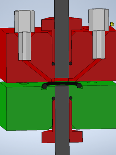
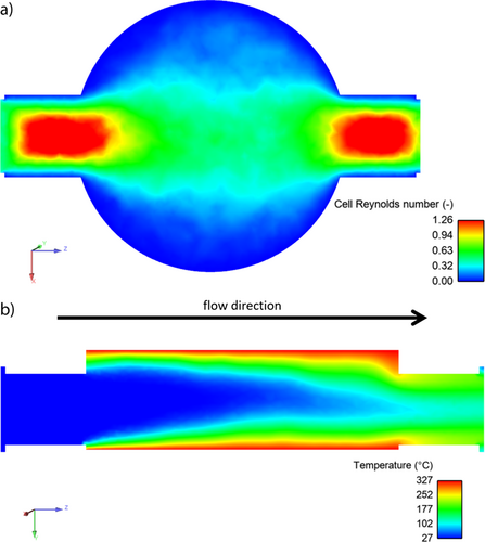
Starting from the HPLC connector, the liquid flows through the channel into the actual electrochemical reaction chamber. It can be seen as a cylinder that is flushed transversely (see Fig. 2). The reactor volume is defined as the space between the rod electrodes. From the resulting shape and an electrode distance of 2 mm, a volume of 60.4 µL is calculated.
Ansys is used for a qualitative complex fluid dynamics (CFD) calculation with parameters given in Sect. S2 of the SI. The cell Reynolds number reveals a laminar profile throughout the whole reactor body. Additionally, it indicates that gas transport from the electrode to the reactor outlet on one hand influences the mixing process and on the other hand must be considered as potential electrode blockage. This is especially important for (Non-)Kolbe electrolysis as gaseous products are formed at both electrodes and elevated current densities lead to increased reaction rates, i.e., increased bubble formation. Furthermore, a concentration profile was mimicked by introducing the electrode surfaces as heat sources. Fig. 2b shows that a certain fraction of the liquid in the middle of the flow channel does not heat up, which means it passes the flow cell unreacted. This is influenced by the current density (resembled by the temperature) and the flow rate. Moreover, the designed reactor shows dead volumes toward the narrowed outlet.
In addition to opposing rod electrodes, a side-by-side arrangement of the rod electrodes is also possible. This reactor design facing sides (FS) is shown in Fig. 3. In contrast to FB, the electrode distance is fixed, which facilitates the assembly of the flow cell. The convex shape of the resulting flow channel can be seen in Fig. 4 and is compared to parallel plate electrodes using CFD calculation. Fig. S5 showing the results for the parallel plate cell may be found in the SI.
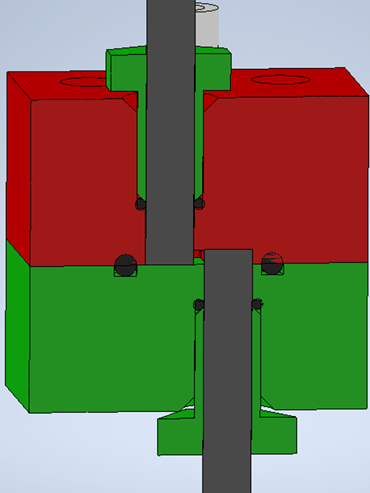
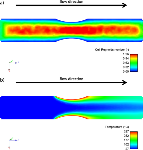
Based on the cell Reynolds number, the flow profiles of FS and a parallel plate cell are very similar. The flow pattern of both is more homogenic than in FB because there is no expansion of the flow channel towards the electrodes. The convex shape introduces a small turbulence and at the same time reduces the electrode distance compared to the parallel plate cell. This is generally desired as a decreased electrode distance lowers the cell potential. Also, the mimicked concentration profile indicates the advantage of this design as it shows a smaller fraction passing the electrodes without reaction.
The optimization process leading to the demonstrated flow cells showed outstanding advantages of 3D printing in the fast development and testing of different reactor designs on a laboratory scale. The properties of the investigated reactors are summarized in Tab. 1.
|
Electrode positioning |
Vcell [µL] |
A [cm2] |
A/V [cm−1] |
|---|---|---|---|
|
Facing bottoms |
60.4 |
0.283 |
4.68 |
|
Facing sides |
11.7 |
0.0685 |
5.87 |
3 Non-Kolbe Electrolysis
 (1)
(1)The overall reaction time tcalc calculated from Faraday's laws 24 is multiplied with the reactor volume Vcell and divided by the reaction solution volume Vreact. For the system investigated herein, τmax equals 130 s in semi-batch Non-Kolbe electrolysis. The focus of this semi-batch investigation was on the residence time regime below 10 s. The results in the flow cells FB (circles) and FS (squares) are depicted in Fig. 5a.
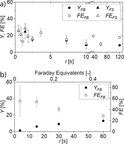
Yields produced in FB are between 10 and 22 %, whereas in FS yields of 34 % are possible. Yield and faradaic efficiency do not show a real trend over the whole range of tested residence times, while it is notable that the experimental error decreases with increasing contact time. This is in accordance with the findings for semi-batch Non-Kolbe electrolysis of biogenic acids in a previous study 11. In both reactor designs, elevated contact time leads to blockage caused by gas bubbles. This especially affects FS, which does not allow a contact time above 10 s because of the narrow flow channel and small reactor volume. The substrate concentration and current density were adapted from the batch study 3 but seem not to yield competitive results. In this regard, literature suggests that advantageous reaction conditions for microreactors can be very specific and should be optimized separately 25.
Because of the decreased electrode surface area of the FS reactor design, elevated residence times are necessary in single-pass electrolysis. Thus, sufficient flow rates to remove the gaseous side products were not achieved. For reactor design FB, a maximum residence time of 60 s enabled sufficient gas removal and a maximum yield of 13 % (see Fig. 5b). Similar to semi-batch electrolysis, the experimental error decreases with increasing residence time. The large error in faradaic efficiency for low residence times also results from low absolute yield values, from which the faradaic efficiency is calculated. Generally, faradaic efficiency and yield show contrary trends already below 0.5 Faraday equivalents. This underlines that chemical follow up reactions and thus selectivity must be considered when molecules with a strong tendency for polymerization are produced electrochemically.
4 Conclusions
The presented design process and testing of 3D printed electrochemical flow cells highlight the potential of these technologies whilst seeking for adaptive sustainable answers in the light of energy transition. Methyl acrylate is an example for an industrially relevant monomer, which is accessible from biomass via selective and current-efficient Non-Kolbe electrolysis of monomethyl succinic acid. In semi-batch reactions, the strong gas evolution at both anode and cathode represents a major hurdle that must be overcome by decreasing the contact time or structuring the microflow cell. Non-Kolbe electrolysis was not affected by the electrode arrangement, whereas a larger volume is more important than the anode-surface-area-to-volume ratio due to the gaseous side products. This is confirmed by single-pass electrosynthesis, which additionally revealed the importance of considering chemical follow up reactions in the production of vinylic monomers.
Supporting Information
Supporting Information for this article can be found under DOI: https://doi.org/10.1002/cite.202100178.
Acknowledgements
This research was funded by the Deutsche Forschungsgemeinschaft (DFG, German Research Foundation) under Germany's Excellence Strategy – Cluster of Excellence 2186 „The Fuel Science Center” – ID: 390919832 and the Studienstiftung des deutschen Volkes e.V. We gratefully thank Christian Gierlich for introducing us to CFD simulations and Janine Baums and Keanu Birkelbach for their valuable time for discussions. Open access funding enabled and organized by Projekt DEAL.
Symbols used
-
- A [cm2]
-
Area, i.e., electrode area
-
- A/V [cm−1]
-
Ratio of electrode area to reactor volume
-
- FE [%]
-
Faradaic efficiency
-
- ID [mm]
-
Inner diameter
-
- V [µL]
-
Volume
-
- Y [%]
-
Yield according to quantitative 1H NMR
Greek letters
-
- τ [s]
-
Hydrodynamic residence time
Sub- and Superscripts
-
- cell
-
Volume in between the electrodes
-
- calc
-
Overall reaction time
-
- max
-
Maximum
-
- react
-
Reactor
Abbreviations
-
- FB
-
facing bottoms
-
- FS
-
facing sides


