Systematic Investigations of Vibrational and Fluid-Mechanical Stability of Coated Monolithic Catalysts
Abstract
Heterogeneous catalysts usually consist of porous, inorganic materials. Especially in the mobile application, e.g., in exhaust gas catalysis as a part of the gas line of an engine, there are loads due to vibrations and high gas velocities. It can be assumed that physical stress will lead to a loss of the catalytically active coating. The present contribution describes experimental setups and methods for a systematic and reproducible investigation of the main influences to the mass loss due to vibrational and fluid-mechanical stress caused by particle-free gas flows.
1 Introduction
Nowadays, heterogeneous catalysts are used in a large number of technical processes. It can be assumed that around 85 % of all modern chemical processes in industry are heterogeneously catalyzed. In addition, the use in exhaust gas cleaning, especially in the cleaning of vehicle and ship exhaust gases, is a wide-ranging area of application. In times of climate change and continually stricter emission regulations, the use of such catalysts is an important part in everyday technical life 1.
Abrasion on the surface of catalysts has several significant consequences. On the one hand, the abrasion leads to a loss of active surface or active material. The removed material is carried away by the gas flow and is therefore irretrievably lost. This leads to a loss of activity, which means that the catalytic converter loses more and more of its performance until it has to be replaced. This usually results in high costs, since the used catalytically active materials are often high-priced precious metals 1. On the other hand, the resulting particles can lead to massive malfunctions in downstream system parts. However, a detailed literature survey showed that there is only little relevant information about gas erosion caused by particle-free flows on solid catalysts. Joshi and Ranade described the occurrence of abrasion on catalyst surfaces, especially in the case of pellet catalysts with high surface loading. They also describe losses of coating materials on ceramic materials due to high gas velocities, but in the presence of fly ash 2. Bartholomew and Farrauto described the flow of a gas stream through a sample in order to determine the decrease in active mass gravimetrically. In connection with the investigation of monolithic honeycomb catalysts, they indicated that a reliable method of determination still needs to be developed 3. Nandakishora et al. described experiments for demonstrating mechanical properties to predict the life expectancy of catalytic material. The influence on the loss of material depending on the angle of impact and the flow velocity were examined. This investigation also assumed non-particle-free flows 4. The lack of information in the literature is probably due to the fact that the focus is usually on combustion processes with downstream catalytic processing of the combustion gases and therefore a particle-free gas cannot be assumed.
At the beginning of the study, it was expected that gas erosion leads to the formation of very small particles, which are also called particulate matter (PM) and ultra-fine particles (UFP). These particles are inhalable and respirable, which can cause breathing problems and lung diseases in humans 5. Therefore, a further focus was on the characterization of the abrasion and the investigation of possible particulate matter and ultra-fine dust components.
2 Materials
For examination, alumina-based 1/8” pellet supports (α-Al2O3 low surface area catalyst support and γ-Al2O3 high surface area catalyst support, both Alfa Aesar) and cylindrical cordierite-based honeycomb supports (cell spacing 0.25 cm – corresponds to 16 cells per cm2 – diameter 17 mm, length 35 mm) were coated with 20 wt % copper oxide as a model system. The preparation was carried out by wet impregnation with an aqueous copper nitrate (≥ 99 % p.a., Acros Organics) solution followed by drying and calcination for at least 3 h. During this time, the samples were exposed to a low gas flow so that decomposition products were reliably removed. A tube furnace was automated for the thermal treatment so that these steps could be carried out fully automated in one step, and thus, with high reproducibility.
3 Experimental Setup
3.1 Vibration-Mechanical Investigation
For investigation of the vibrational resistance of the coating, a specially developed and 3D-printed modular experimental setup that could be mounted on a conventional sieving machine with adjustable amplitude was used to fix the samples and stress them with different degrees of vibration. Fig. 1 shows this setup for pellet beds (a), which could also be used for honeycomb samples by adding two inserts (b).

3.2 Fluid-Mechanical Investigation
Another setup was used for flow mechanical examination of coated samples in a plug-flow reactor. This setup consisted of a 9.9-kW heating element, which was regulated with high accuracy by a programmable logic controller (PLC). The air flow was set by a mass flow controller (MFC) with a maximum flow rate of 400 L min−1 under standard conditions, which is controlled by software developed for this purpose.
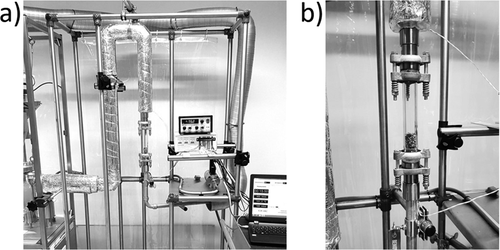
The pipe connections between the heating element and the rest of the components were made from commercially available galvanized ¾" steel pipes. Special stainless-steel adapters have been used for the transition to the glass reactors using KF25 ball flanges. Fig. 2 shows an overview of the experimental setup (a) and one of the tailor-made glass reactors in detail (b).
The dimensioning of the glass reactors was based on various criteria. The inner diameter of the reactors for the honeycomb catalyst samples was given by the outer diameter of the honeycomb of 17 mm. In order to avoid mechanical tension, the pipe diameter had to be slightly larger and was set to 18.4 mm. This corresponds to a standard dimension for thick-walled glass tubes.
The inner diameter for the pellet-shaped catalyst samples should be the same size as the honeycomb bodies. On the other hand, it must be taken into account that ten times the diameter of the individual particles is normally taken as a reference for the minimum dimension for bulk material. In the present case, the pellets had a diameter of around 3 mm. As a compromise between both criteria, a standard glass tube with a nominal diameter of 25 mm was chosen for this reactor.
KF25 ball flanges according to DIN standards were selected for the transition from the reactors to other pipeline parts. These have a nominal diameter of 25 mm, are tight with suitable seals even at moderate overpressures and high temperatures and have an installation tolerance of around 3° angular offset, so that slight corrections for exactly vertical installation of the reactor are possible 6.
4 Results and Discussion
4.1 Vibration-Mechanical Investigation
First, simple test series with increasing vibration intensity were carried out using a pellet bed. Up to a setting of the vibration intensity of 60 % (corresponds to about 1.3 mm amplitude at a frequency of 50 Hz), no deviations were found. Above a value of 60 % of the maximum intensity, the vibration changed significantly, which was visible by particles leaving the apparatus and acoustically by a massive increased noise level. The optical inspection of the sample shows that the material has been mechanically destroyed. It is obvious that from a setting of 60 % onwards there were movements within the pellet bed and the particles damaged each other.
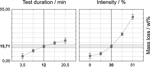
Quantitative examination of the results was achieved by a two-dimensional statistical experimental design, where the two controllable influencing factors on the loss of material (vibration intensity and test duration) were considered. The limits of the experimental parameters resulted for the vibration intensity from the preliminary tests between 9 and 51 % of the maximum possible intensity. For the test duration, limits were set at 3.5 to 20.5 min, also based on previous tests.
As can be seen in Fig. 3, vibration intensity was identified as the most significant parameter of the vibrational testing in the case of pellets. The influence of duration was low and approximates to a constant value with increasing duration.
The investigations regarding the cordierite honeycomb catalysts were carried out under the same and subsequently stronger conditions (intensity increased up to 100 %). This test series led to the conclusion that under the given conditions no gravimetrically measurable loss could be detected for the coated honeycomb support.
4.2 Fluid-Mechanical Investigation
The fluid mechanics were also investigated with a statistical experimental design. For this purpose, the temperature in the reactor, the duration of the experiment and the gas volume flow were identified as the most influencing factors. Therefore, the investigation was carried out with a three-dimensional experimental design.
The limits of the experimental parameters are ambient temperature as the lower value for temperature. At the time of the experiments, a maximum of 200 °C was technically possible as the upper value. The gas volume flow was regulated from 30–70 % via the opening of the MFC – corresponding to gas volume flows of 120–280 L min−1 under standard conditions. This results in gas hourly space velocities (GHSV) values of 450 000 to 1 690 000 h−1 based on the volume that the pellet bed occupies in the reactor. These high GHSV values were chosen so that fluid-mechanical aging was achieved in a short period of time and the test duration could be reduced to 2–4 h for reasons of feasibility.
For the fluid-mechanical investigation, the main influence determined for the pellet system was the gas volume flow (Fig. 4). A change in mass loss due to a temperature effect was not observed (cannot be distinguished from the experimental noise).

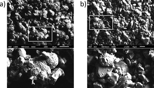
Fig. 5 shows SEM images of a fresh (a) and a flow-mechanically stressed alumina sample (b). The basic structures of alumina as well as porous copper oxide appearing as bright sponge-like particles are clearly visible. After the test, significant amounts of the copper oxide are detached from the basic structure.
Afterwards, coated cordierite honeycombs were tested applying the same set of parameters. As in the case of the vibration test, no significant loss was caused by a fluid-mechanical load. For the validation of the test results from the fluid-mechanical investigations and for the characterization of the abrasion, tests for the determination of particulate matter and ultra-fine particle were performed.
For this purpose, a diffuser and a glass tube were installed at the end of the pipeline behind the reactor, which expanded the diameter of the pipe to a nominal width of 100 mm. In this way, the flow velocity at the measuring point was reduced to a value of 0.5–1 m s−1. The particulate matter fractions PM10, PM2.5 and PM1 were measured with an optical particle counter of type GRIMM 1.109, the ultra-fine particles were recorded using a DiSCmini ultra-fine dust measuring device.
It is consistent with the previously determined results that in the experiments with alumina pellets significantly increased particle mass concentration of the PM10 fraction were detected, especially during the first hours (Fig. 6).
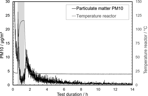
Formation of ultra-fine particles was not observed. Further series of tests on coated cordierite honeycombs confirmed the previous result that no significant loss of coated surface occurs under the applied test conditions. Once more, a significant thermal influence could be excluded.
4.3 Transfer to a Real Catalytic Converter System
After the test apparatuses had been validated with the CuO model systems, they could be used for the investigation of real catalysts. Two catalytic systems from a current research project of Fraunhofer Institute UMSICHT in Oberhausen were investigated with a focus on their fluid-mechanical resistance. On the one hand, it was an impregnated catalyst honeycomb coated with cerium and manganese oxide, and on the other hand an extruded catalyst, which consists of 50 % cerium and manganese oxide and 50 % binder. Using the experience achieved from method development, the investigations were carried out at room temperature with a standard volume flow of 280 L min−1 for a period of 4 h. These test conditions resulted in a GHSV value of 1 940 000 h−1 based on the volume of the honeycomb in the reactor. Compared to real conditions of use with a GHSV value of approx. 80 000 h−1, the samples were massively overloaded in order to simulate fluid-mechanical aging, as with the CuO reference system.
The honeycombs impregnated in the conventional way showed a similar behavior to the CuO-coated reference. Also, no measurable loss of mass was detected using conventional laboratory equipment. The extruded honeycombs showed a different result. During the test, it lost around 0.3 wt % of its total mass. To validate this result, another particle measurement was carried out during fluid-mechanical investigation. In the first few minutes, a higher mass concentration of particles of the PM10 fraction could be detected. The integration of the values from the first 300 s provided a value four times higher for the extruded catalyst. It could be seen that the greatest abrasion again occurs in the first minutes after starting the test.
In addition, both systems were analyzed regarding their vibration-mechanical stability. The testing was carried out like the previous investigations. Comparable to the CuO reference system, the impregnated honeycomb was very stable in terms of vibration mechanics. Even at maximum vibration intensity, which corresponds to a resulting amplitude of about 2.3 mm at 50 Hz, the loss of mass was only 0.038 wt %. In comparison with the conventionally impregnated CeO2/MnO2/cordierite honeycomb and the CuO/cordierite reference system, the extruded CeO2/MnO2 catalyst had a slightly lower vibration-mechanical stability. However, further series of measurements must be carried out for additional conclusions, in particular regarding the influence of the test duration.
5 Conclusions and Outlook
The aim of the study was to evaluate the stability of coated cordierite honeycomb catalysts and extruded integrated catalysts. Due to the lack of literature, own experimental setups and methods for the systematic, reproducible determination and quantification of coating losses were successfully developed. It could be seen that a CuO model system and the tested catalyst systems have high stability in relation to mechanical aging.
With the developed methods, catalyst manufacturers receive important information on the mechanical stability of various systems, which contributes to the successful development of new systems. The methods also provide important information for research projects at Fraunhofer UMSICHT on extruded integrated catalysts.
Due to its design, the system is suitable to be expanded to include additional influencing parameters. For further investigations, the next step is to equip the apparatus with a steam saturator and particle dosing.
The long-term aim is to develop a system for testing catalyst systems under even more realistic conditions. The concept should offer maximum flexibility so that samples can be examined by a quick test, but also by long-term investigations.
Acknowledgements
Open access funding enabled and organized by Projekt DEAL.
Symbols used
-
- GHSV [h−1]
-
gas hourly space velocity
Abbreviations
-
- MFC
-
mass flow controller
-
- PLC
-
programmable logic controller
-
- PM
-
particulate matter
-
- SEM
-
scanning electron microscope
-
- UFP
-
ultra-fine particles


