Constructing highly rough skin layer of thin film (nano)composite polyamide membranes to enhance separation performance: A review
Funding information: National Natural Science Foundation of China, Grant/Award Number: 32172340; Postgraduate Research Ability Enhancement Project, Grant/Award Numbers: 19008021082, 19008022056; Research Foundation for Youth Scholars of Beijing Technology and Business University, Grant/Award Number: QNJJ2020-18; Scientific Technological Innovation Service Ability Construction-Basic Scientific Research Funding, Grant/Award Number: PXM2020_014213_000017
Abstract
The thin-film (nano)composite (TFC or TFN) polyamide membrane prepared by interfacial polymerization method has a wide range of applications in water treatment. The preparation of TFC or TFN membrane with a highly wrinkled morphology in the selective layer can significantly improve the permeability of the membrane and is an effective way to break the “trade-off” effect. However, the formation mechanism of highly rough skin layer and the membrane fouling performance associated with the rough structure have been underexplored. In this review, the formation mechanisms of crumpled membranes were summarized into four aspects: interfacial nanobubbles effect, template method, diffusion-driven instability, and co-solvent effects. On the basis of these mechanisms, researchers have explored different methods to construct membranes with highly rough structures. This article summarized these construction methods including introduction of additives, construction of functional interlayer, sacrificial template and some other strategies. The advantages and disadvantages of these fabrication methods and the separation performance comparison of the crumpled membrane and the original membrane were discussed in detail. Furthermore, the review analyzed the recent research status of the anti-fouling performance of the pleated membrane, and finally put forward the research opinions on the future in fabricating highly roughness membranes.
1 INTRODUCTION
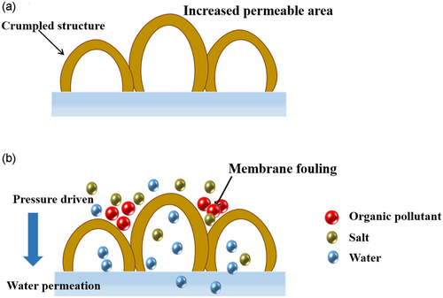
Influenced by the rapid growth of population and economy, water pollution and shortage of freshwater resources have become global challenges.1-3 Numerous researches are devoted to improving the supply of freshwater through desalination of seawater/brackish water or reuse of wastewater.4-7 Among the existing technologies, pressure-driven membrane technologies such as reverse osmosis and nanofiltration are widely used in the fields of reducing environmental pollution and desalination for their low energy consumption, simple process, easy scale, and high rejection of ions.8, 9 Reverse osmosis and nanofiltration membranes prepared based on interfacial polymerization technology have been used in large-scale and low-cost water purification applications.10-13 In the typical fabrication process, the organic amine monomer is dissolved in water and the acid chloride monomer is dissolved in an organic solvent, which the two are not mutually soluble. The thin insoluble polyamide (PA) layer is formed at the oil–water interface and adheres to the surface of the support layer. Although the performance of PA membrane has been greatly improved in the past few decades, the trade-off effect between selectivity and permeability, has always restricted the application of TFC membranes.14-16 In order to break the trade-off effect, many methods such as surface modification, preparing an ultrathin selective layer and introducing water channel molecules have been studied17-19 (Figure 1). However, the ultra-thin membranes are prone to achieve poor mechanical properties and defects reducing the selectivity, and the introduction of water channel molecules needs to consider the compatibility between the additives and the membrane matrix. In contrast, without losing selectivity, preparing a PA layer with a crumpled structure to increase the effective filtration area of the membrane is an feasible strategy to improve membrane performance20 (Figure 2a).

Although m-phenylenediamine (MPD)-based reverse osmosis (RO) membranes have been found to obtain hollow leaf-like or large ridge-valley structure in a long time (commercial RO membranes also have this feature) with simple manipulating reactant concentration to tune surface morphology from smooth to hollow nodules and leaf-like structure21 or increasing polymerization time to change morphology from nodular and leaf-like to hill and valley,22 the formation mechanism of the ridge-and-valley structure on the membrane surface has been confirmed by researchers in recent years.23 However, piperazine (PIP)-based nanofiltration membrane exhibits node-shaped surface, which is much different from MPD-based RO membranes.24 In addition, some emerging methods and principles for the membrane preparation of large effective filtration area have also been explored, such as Turing structured membranes,20 template method,25 co-solvent effect.26 These methods have greatly broadened the understanding of rough membranes to researchers. Based on the above principles of constructing highly rough fold membranes, researchers have adopted different methods to realize crumpled membranes. The introduction of additives is a simple and effective means for improving the separation performance of TFC membranes. The role of the additive can be a template, co-solvent or regulator to control the diffusion rate of reactive monomer. The supporting layer plays an important role on the PA active layer. Reports have found that appropriate large pore size of the substrate is prone to form a ridge-and-valley structured PA layer,27-30 but overlarge pores seems to suppress the typical ridge-and-valley structure.31 A dense and thick sponge-like substrate is prone to induce the generation of small and loose ridge-and-valley structured PA layer.32 Therefore, manipulating the chemical composition and structure of the substrates could be sufficient for fabricating highly rough membranes.
Certainly, the membrane with crumpled outlook gives a bad impression on antifouling performance by most of academic workers.33-35 The concavities of the folds are easy to accumulate pollutants and cause flux attenuation36 as depicted in Figure 2b. Under the same operating pressure, the pleated membrane exhibits a faster flux decline rate.37 However, there are papers report the relationship between rough structure and pollution resistance successively in recent years, which is believed to be a great inspiration for the preparation of high-level roughness membranes.38-40 Therefore, this article reviews the reports in recent years in terms of the formation mechanism, strategy, performance comparison and anti-fouling properties of high-roughness membranes, and provides insights for the preparation and application of state-of-the-art membranes.
2 FORMATION MECHANISMS OF CRUMPLED STRUCTURE MEMBRANE
2.1 Interfacial nanobubbles effect
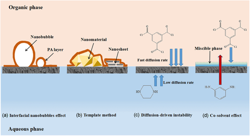
MPD based PA membrane could achieve hollow nodules, ridge-and-valley or leaf-like structure by rising reactant monomers concentration or extending reaction time.21, 22 The formation mechanism had been proposed by Ma et al.23 for degassing the gas bubbles produced from reaction heat and release of acid as depicted in Figure 3a. The interfacial polymerization reaction between MPD and trimesoyl chloride (TMC) is an exothermic reaction who producing heat to decrease the solubility of carbon dioxide (CO2). At the same time, the reaction generates excess acid, which combines with the bicarbonate ions in the solution to yield CO2 nanobubbles. These bubbles will move to the PA membrane formation side due to the obstructive effect of the support membrane, thereby forming hollow nodules morphology in PA selective layer.41 Many honeycomb-shaped pores can be observed on the back of most PA selective layers with ridge-and-valley structure. That is because the rapidly formed tight PA film interrupted the gas to escape from the interface side. The bubbles have to release to the substrates to unseal of the nanovoids.42 Since the temperature near the interfacial polymerization (IP) reaction region reached as high as 90°C,43 Tang et al.44 brought forward that the reacting heat could vaporize organic solvent to promote the formation of hollow nodules. High vapor pressure (or low boiling point) organic solvent contributed to large and/or many voids on the basis of the same principle of trapped gas bubbles.
2.2 Template method
The template method is to form a substrate with a physically rough structure surface as the support membrane for PA membrane. The interfacial polymerization reaction is affected by steric hindrance, as a result, PA layer grows along the uneven height and sturdy substrate gaining the rough topography as shown in Figure 3b. The roughened template was prepared by pre-deposition nanoparticles or nanofibers on the surface of the support membrane, incorporating nanoparticles into the reaction solution for IP process or in-situ growth of nanoparticles. However, the shape and size of the nanoparticles as well as addition strategy has a great influence on the morphology of the PA layer. According to different shapes of nanoparticles, i.e. nanosheets, octahedral spheres and nanorods, the synthesized PA film can have wrinkled corridor at the edge of nanosheets, interconnected tubular wrinkle connected and sustained by nanoparticle pillar, ridge-like folded structures formed by rod-like structured nanoparticles.45 In addition, some researchers choose to remove the template after the interface polymerization which is also called the sacrificial template method.25, 46
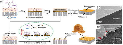
2.3 Diffusion-driven instability
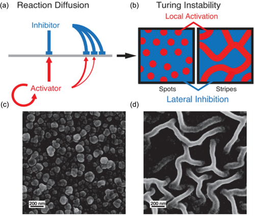
The fold structure of PA film caused by diffusion-driven instability was first proposed by Zhang et al.20 Inspired by Turing morphology, “local activation and lateral inhibition” phenomenon will be formed when the diffusion coefficient of the inhibitor monomer is much greater than that of the activator monomer in a reaction–diffusion system which is far from the thermodynamic equilibrium. This phenomenon underlies diffusion-drive instability. In the process of interfacial polymerization for TFC PA membranes, organic amine monomers are commonly used as activators and acyl chloride monomers are inhibitors. During the reaction, the aqueous solution contained activator is confined in the nanopores of the supporting substrate, which physically hinders the movement of the water phase and slows down the transport of the activator. By adding a certain amount of macromolecular substances to the water phase, or preparing a more water-affinity supporting membrane will establish interaction between the additives/substrates and the activator through hydrogen bond, ionic bond and other forces to limit their diffusion, thereby reducing a large extent of diffusion rate of the activator (Figure 3c). Alternatively, by increasing diffusion procedures i.e., adding the precursor activator to the organic phase solution and hydrolysis into reactive amine monomer, limits the diffusion rate of the activator by delaying the diffusion reaction.14 In this way, through the synergistic effect of physical hindrance and chemical interaction, the appropriate difference in the diffusion coefficients of the activator and the inhibitor can be satisfied, leading to instability of the diffusion drive, and generating nano-scale spots and stripe-like wrinkled PA layers.
2.4 Co-solvent effect
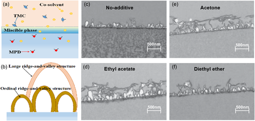
Since Kwak47 added dimethyl sulfoxide (DMSO) into organic solution to tune the membrane structure, many kinds of co-solvents were investigated to introduce into the IP process for regulating the morphology of the PA layer. As co-solvents participated, the membrane surface usually exhibited a multi-layered ridge-and-valley pattern. The formation mechanism was displayed by Kamada26 as Figure 3d showed. A “miscible phase” was taken shape by addition of co-solvent which accelerated the transport rate of amine monomer. The fast moving MPD molecules reacted with organic phase monomer to bridge a “large size” PA arch. After the co-solvent transferred to the water phase, the miscible phase disappeared and left the first PA layer in the organic solution. At this time, the original small sized ridged-and-valley structure PA begun to establish. As a result, a multi-layered, large-sized ridge-and-valley membrane structure was formed, which increased the effective filtration area of the membrane.
3 CONSTRUCTION STRATEGIES OF CRUMPLED STRUCTURE MEMBRANE
3.1 Introduction of additives
Adding a certain mass of additives to the aqueous solution or organic solution is the most widely used method for simplicity, easy to scale and a wide range of options to prepare highly rough membranes. The additives used can be assorted into polymers, organic solvents, nanomaterials, inorganic salts, biomass, etc.
3.1.1 Polymers
Introducing a water-soluble polymer into the aqueous solution of the interfacial polymerization reaction is an effective method to prepare a membrane with a crumpled structure. Chae and Kim48 added polyethylene glycol (PEG) with a molecular weight of 200 Da and piperazine to water to prepare a PA membrane. Compared with PIP, small-sized PEG molecules have better solubility in the oil phase and are easier to diffuse from aqueous solution to organic solution. The PEG drives PIP molecules to diffuse into oil phase by hydrogen bond to form a widespread PA membrane. The surface roughness of the resulting membrane was increased by 7 times, and the water permeability increased 41% compared to the control membrane.
Another polymer introduced into the aqueous interfacial polymerization reaction solution is polyvinyl alcohol (PVA). Zhang et al.20 added PVA with a molecular weight of 85,000–124,000 to the PIP aqueous solution. The diffusion rate of PIP was sharply reduced by the increase of the aqueous solution viscosity through PVA addition, the barrier of the substrate pore size to PIP and the hydrogen bonding between PVA and PIP. In this way, the instability of the diffusion-drive is realized, which forms the dot-like and stripe-like protrusion film with Turing structure (Figure 4). Another research also confirmed that adding PVA in the aqueous solution created nodules although the PA layer was generated on the roughness fibrous support. The polymer in reaction solution induced difference in monomer diffusion rate leading to heterogeneous roughness morphology.46
3.1.2 Organic solvent
Introducing organic solvent into the interfacial polymerization process to improve the compatibility of water and oil phase forms a mutually soluble microdomain. The reactive monomers polymerize in the microdomain, which widens the reaction site and forms a wider PA film. Commonly used organic solvents added to the organic phase are acetone (AC),26, 49-53 propanone, butanone,54 ethyl acetate,53 diethyl ether, toluene, isopropyl alcohol (IPA), and N,N′-dimethyl formamide (DMF)26 in hexane, AC, ethyl acetate, and diethyl ether in dodecane,55 and diethyl ether or ethyl acetate in heptane.56 And some so-solvents including DMSO,47, 57 methanol,50 alcohols58 and dimethyl sulfoxide47, 59 were added into aqueous phase.
Sadrzadeh et al.57 studied different parameters on synergistic impacts on permeability of PA membranes and discovered that DMSO as a co-solvent largely contributed to the variation of the water flux. Kamada et al.26 added co-solvents, that is, acetone, ethyl acetate, diethyl ether, toluene, IPA and DMF, into organic phase to control surface morphology and PA network structures. As the co-solvents improved the compatibility of the two-phase solution, a multi-layered ridge-and-valley structure of PA membrane was created as seen in Figure 5. Further, they discovered the structure of PA layer varied with different concentration of co-solvent. In the case of diethyl ether, the ordinal ridge-valley structure in PA layer gradually increases which ranged from 100 to 500 nm with the increase of the co-solvent content as the concentration of diethyl ether was lower than 5%. But the PA layer became smooth and widespread with size of more than 1 μm when the diethyl ether concentration reaches 5%, covering almost the entire film surface for a multilayer structure.53 Tsuru and co-workers52 used AC as co-solvent in organic solution for IP process. Although the surface was smooth for co-solvent involved membrane, the multi-layered structure PA selective layer was generated for improve water permeability. In addition, the membranes with co-solvent participated exhibited increased pore size, thinned, and opened dense layer.51 Zhou and Wang60 used a green co-solvent (dimethyl carbonate) to prepare PA RO membrane. The leaf-like structure was pronounced by adding the co-solvent as the roughness average (Ra) increased from 38.4 to 115.0 nm. Liang et al.61 tailored the amine diffusivity in organic phase composed of benzene and n-hexane mixtures for manipulating the nanofilm structure. The amine diffused faster at higher benzene content, resulting in a rougher and thicker nanofilm.
3.1.3 Inorganic salts
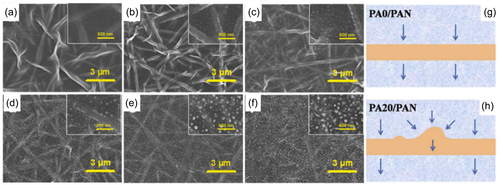
The inorganic salt crystallizes out after heating, compositing a template with rough structure, thus forcing the flat PA membrane to crumpled nanostructure. Mi et. Al.62 using NaCl, KCl, Na2SO4, KNO3, and CaCl2 as sacrifice template to form crumpled PA layer. The root mean square (RMS) roughness increased from 13.63 to 34.21 nm by adding NaCl (<2 wt%) into the aqueous reaction solution. The structure of the PA layer was tuned by NaCl concentration which high concentration promoted the more and larger crystals contributing to an increasing density and size of the raised knots or folds. However, the concentration of salt is far from saturation concentration. As appropriate high concentration of salt could break the hydrogen bonds in the nearby water molecules which attributed to the existence of discrete voids in the salts leading to enhance the electrostatic ordering in the aqueous solution, the mass transfer of PIP molecules in the aqueous phase was promoted, thus affecting the IP reaction process.63, 64 Also, high content of NaCl in the water phase could complex with the carbonyl groups of the PA incurring the uneven distribution of the IP reaction, which promote the formation of large nodular structures on the membrane surfaces. With 20 wt% NaCl in aqueous solution, the produced membrane showed nodular arrays with 32–87 nm in height and 90–160 nm in width as shown in Figure 6.65
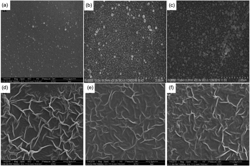
As CO2 bubbles generated from the heat of reaction and acid gave acid to increase the membrane surface roughness, Tang et al.23 added NaHCO3 to the aqueous solution for enhancing nanobubbles in preparing a leaf-like structure PA film. Furthermore, An et al.66 prepared a striped pleated membrane by adjusting the concentration of PIP and TMC, and then introduced NaHCO3 to fabricate a reinforced nanostructured film. The RMS turns from 10.6 nm of controlled membrane to 25.6 nm of the striped membrane and eventually into 104 nm of the enhanced nanostructure membrane. And the permeabilities of these membranes are 7.5, 11.4, and 17.2 L/(m2·h·bar), respectively.
3.1.4 Nanomaterials
Nanomaterials have been applied to improve membrane structure and properties for a long time as their unique properties.67, 68 The addition of traditional inorganic nanomaterials to the thin layer of nanofiltration membrane improves the hydrophilicity of the membrane and increases the permeation flux. The introduction of nanomaterials naturally forms a rough structure and provides additional water channels in porous nanomaterials. In recent years, the materials used to prepare high permeability nanocomposite membranes with roughness structure showed increasing attention to researchers.
One-dimensional nanomaterials such as nanotubes, cellulose nanofibers, gold nanorods, etc. were used to incorporate into the PA layer to prepare nanofiltration membranes with rough structures. Carboxylated single-walled carbon nanotubes (COOH-SWCNT),69 aluminosilicate nanotubes,70 titanate nanotubes (TNTs),71, 72 and halloysite nanotubes (HNTs) nanotubes73 were embedded into thin PA layer to build a rough surface. As the loading of nanomaterials increasing, more visible “leaf-like” structures were observed. Cellulose nanocrystals were prepared by different strategy and added into the aqueous solution for promoting permeability of PA membrane.74, 75 The PA surface transferred from flat to striped folds by elevating cellulose concentration to 0.05% as the cellulose nanocrystals increased the reaction rate of IP (Figure 7). Similarly, Au nanorods were incorporated into the PA membrane selective layer to construct a crumpled structure as the nanoparticles served as a template to improve the surface roughness.45
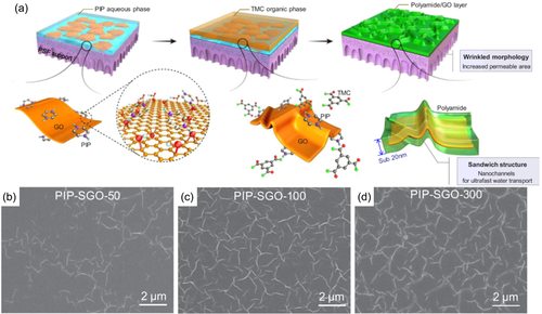
Graphene oxide (GO), a two-dimensional nanomaterial with abundant oxygen-containing functional groups at the edges and surfaces, has been concerned with special mass transport pathways and great potential in liquid separation. Zhu and coworkers76 in-situ embedding GO into separation layer of PA membranes via IP. The incorporation of GO in the membrane created a sandwich wrinkled structure surface with sub-20 nm PA layer as shown in Figure 8. The wrinkles were generated by the templates of the GO nanosheets and the hydrophilic functional groups on the basal planes and edges of GO. Similar conclusion was found in other literatures as GO incorporated in the PA layer to increase surface roughness.77-81 Except GO, other two-dimensional nanomaterials (e.g., MoS2, g-C3N4, LDHs) had been applied in PA membranes due to their impressive physicochemical properties.82-85 MoS2 nanosheets modified with tannic acid (TA)-Fe3+ coordination complexes were incorporated in the PA layer to create TFN nanofiltration (NF) membranes.84 Compared to the origin TFC membrane, TA-MoS2 membrane has a significant conversion in membrane surface morphology with the appearance of visible protuberances. Another novel TFC membrane was fabricated by embedding functionalized boron nitride nanosheets (FBNS) into the PA layer with expansion of homogenous leaf-like structure.86 The membrane also showed great chlorine resistance, performance stability, and antifouling behavior.
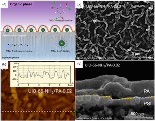
3-dimentional nanoparticles with inherent porous inside the materials gained increasing attention for improving the membrane performance. Metal organic frame (MOF), possessing outstanding advantages of hydrophilicity and sieving micropores, showed great potential in water treatment.87 UiO-66 and its derivatives have been investigated as nanofillers in TFN membranes for NF, forward osmosis (FO) and RO for their outstanding stability in aqueous solution. Yuan et al.88 conducted a facile vacuum filtration method for loading UiO-66-NH2 containing amine aqueous and then initiated IP procedure. The positioned MOF nanoaggregates acted as pillars for PA film facilitating a rough, fishnet-like surface which greatly promoted the membrane effective surface area. Su et al.89 demonstrated a homogeneous nanoscale striped Turing structure membrane by UiO-66-NH2 mediated as seen in Figure 9c. The MOF nanoparticles achieved strong interactions with aqueous amine monomer, that is, triethylenetetramine. An intermediate complex was in situ formed which lower the diffusion rate of triethylenetetramine resulting in the generation of Turing structure membrane as depicted in Figure 9. Other UiO-66 series incorporated PA membranes had been studied for improving membrane permeance, also.90-92 Some other 3-dimentional nanomaterials were involved in PA selective layers. Yu et al.93 synthesized a novel nanoporous covalent organic framework (COF) and deposited it onto a substrate to induce crumpled PA layers. The surface of the membrane gradually turned from tent-like to mesh morphology with increasing the amount of incorporated COF. Zhang et al.94, 95 introduced o-hydroxy porous organic polymer (o-POP) into thin film composite membranes to fabricate high flux nanofiltration membranes. The phenolic OH on the o-POP showed strong interactions of electrostatic attraction and hydrogen bonding with aqueous monomers which limited their diffusion rate across the organic boundary. Also, the viscosity of the aqueous phase increased by adding the porous polymer which slowed down the diffusion of ammine monomers contributing to a regularly wrinkled ring-shape surface. Xu et al.96 developed a carbon quantum dots (CQD) doped TFN membrane on ceramic hollow fiber support. The PA layer become thinner and rougher as CQD incorporated into the PA layer due to the nanoparticles template and inhibition of the amine monomer diffusion. Also, incorporating carbon dots into the PA membrane increased the roughness from 31.5 to 78.5 nm as the leaf-like structure turned into ridge-and-valley.97
3.1.5 Others
Some biological reagents are also used to improve the structure and performance of membranes, such as taurine, liposomes, glutamine and glycine, etc.98-100 Wang et al.99 first add liposomes to the amine monomer solution for IP process. The liposome underneath PA skin layer achieved many nanovoids and ring-shape wrinkled to raise surface roughness and reduce hydrophobicity. Gao et al.100 developed a striped surface of PA nanofiltration membrane by introducing taurine into the reaction system. The surface roughness heightened from 3.54 to 7.17 nm by increasing the taurine concentration. Also, the hydrophilicity was greatly improved by addition of taurine which composed amino and sulfonic groups, thus promoted anti-fouling performance. Tannic acid (TA) was a commonly used modifier for membrane and supporting material. A trace quantity of TA was incorporated into the aqueous phase for preparing a rough and dense PA membrane. TA with abundant hydroxyl group limited the diffusion of PIP constructing diffusion-driven instability for Turing structure membrane.101 In addition, sodium lauryl sulfate (SLS) can improve the interfacial polymerization conditions effectively.102 In the present of SLS, the membrane displayed even ridge-and-valley structure. And the roughness of the SLS-containing membrane increased with the content of SLS. The performance and IP condition of additives incorporated PA membranes are summarized in Table 1.
| Category | Additives used | Loading amount (optimum) | Incorporated phase | IP condition (optimum) | Surface roughness (optimum) | Performance (optimum) | Ref |
|---|---|---|---|---|---|---|---|
| Polymers | PEG | Aqueous | 4 wt% PIP/water 0.2 w/v% TMC | Ra = 77.6 nm | Water permeation flux increased by 41% while the rejection rate of Na2SO4 remained at 99.6%. | [48] | |
| Polymers | PVA | Aqueous | Ra = 119 nm | Water permeation flux of 24.79 L.m−2.h−1.bar−1 and rejection of 99.6% for Na2SO4. | [20] | ||
| Organic solvent | Ethyl acetate | 2 wt% Ethyl acetate/n-hexane | Organic | 2 wt% MPD/water 0.1 wt% TMC | A water flux of more than 1 m3/(m2·d) at 1.5 MPa with a NaCl rejection of 99%. | [26] | |
| Organic solvent | Acetone | 2 wt% Acetate/n-hexane | Organic | 2 wt% MPD/water 0.1 wt% TMC | NaCl rejection remained at 99%. | [51] | |
| Organic solvent | Dimethyl carbonate (DMC) | 1.5% DMC/n-hexane | Organic | 4.6 w/v% MPD/water 0.12 w/v% TMC | Ra = 101.6 nm | Water permeation flux of 5.84 L.m−2.h−1.bar−1 and rejection of 99.25% for NaCl. | [60] |
| Organic solvent | Benzene | N-hexane: Benzene = 25:75 | Organic | 3.0 wt% MPD/water 0.15 wt% TMC | Ra ≈ 92.7 nm | Water permeation flux of 2.2 L.m−2.h−1.bar−1 and rejection of 99% for NaCl. | [61] |
| Inorganic salts | NaCl | 1.0 wt% NaCl/water | Aqueous | 0.2 wt% PIP/water 0.1 wt% TMC | RMS = 23.27 nm | Water permeation flux of 21.22 L.m−2.h−1.bar−1 and rejection of 96.2% for Na2SO4. | [62] |
| Inorganic salts | NaCl | NaCl/water 20.0 wt% | Aqueous | 1.0 wt% PIP/water 0.2 wt% TMC | Water permeation flux of 25.8 L.m−2.h−1.bar−1 and rejection of 99.1% for Na2SO4. | [65] | |
| Inorganic salts | NaHCO3 | NaHCO3/water 6 wt% | Aqueous | 0.48 w/v% PIP/water 0.21 w/v% TMC | RMS = 104 nm | Water permeation flux of 17.2 L.m−2.h−1.bar−1 and rejection of 99.3% for Na2SO4. | [66] |
| Nanomaterials | Aluminosilicate nanotubes (ANTs) | ANTs/water 0.2 w/v% | Aqueous | 3.4 wt% MPD/water 0.15 wt% TMC | Ra = 114 nm | A water permeating flux of 5.63 L.m−2.h−1 | [70] |
| Nanomaterials | Amino titanate nanotubes (TNTs) | TNTs/n-hexane 0.05 w/v% | Organic | 2 w/v% MPD/water 0.1 w/v% TMC | Ra = 28.1 nm | Water permeation flux of 2.45 L.m−2.h−1.bar−1 and rejection of 96.53% for NaCl. | [71] |
| Nanomaterials | Amino titanate nanotubes (TNTs) | TNTs/n-hexane 0.05 w/v% | Organic | 2 w/v% MPD/water 0.1 w/v% TMC | Ra = 28.1 nm | Water permeation flux of 2.45 L.m−2.h−1.bar−1 and rejection of 96.53% for NaCl. | [72] |
| Nanomaterials | Halloysite nanotubes (HNTs) | HNTs/n-hexane 0.05 wt/v% | Organic | 2 w/v% MPD/water 0.1 w/v% TMC | Ra = 61.4 nm | Water permeation flux of 2.4 L.m−2.h−1.bar−1 and rejection of 95.6% for NaCl. | [73] |
| Nanomaterials | Graphene oxide (GO)、 Polyvinyl alcohol (PVA) |
100 ppm GO and 0.05 wt % PVA | Aqueous | 1.0 wt% PIP/water 0.1 wt% TMC | Ra = 64.8 nm | Water permeation flux of 84.2 L.m−2.h−1 at 0.55 Mpa and rejection of 97.6% for Na2SO4. | [81] |
| Nanomaterials | g-C3N4 nanosheets (CNs) | CNs/water 0.0025 wt% | Aqueous | 0.1 wt% PIP/water 0.15 wt% TMC | RMS = 139 nm | Water permeation flux of 18.8 L.m−2.h−1.bar−1 and rejection of 84% for Na2SO4. | [82] |
| Nanomaterials | Graphene oxide (GO) | GO/n-hexane 0.0015 wt% | Organic | 2.0 wt% MPD/water 0.15 wt% TMC | Water permeation flux of 2.97 L.m−2.h−1.bar−1 and rejection of 93.8% for NaCl. | [80] | |
| Nanomaterials | Acyl chlorided graphene oxide (GO-COCl) | GO-COCl/n-hexane 0.002 w/v% | Organic | 3 w/v% PIP/water 0.15 w/v% TMC | RMS = 54.7 nm | Water permeation flux of 22.6 L.m−2.h−1 at 0.6 Mpa and rejection of 97.1 for Na2SO4. | [79] |
| Nanomaterials | Graphene oxide (GO) |
Aqueous | 0.9 wt% PIP/water 0.01 wt% TMC | Water permeation flux of 24.2 L.m−2.h−1.bar−1 and rejection of 88.8% for Na2SO4. | [76] | ||
| Nanomaterials | Graphene oxide (GO) |
Aqueous | 0.9 wt% PIP/water 0.01 wt% TMC | [77] | |||
| Nanomaterials | Layered double hydroxides (LDHs) | Aqueous | A water permeating flux of 33.2 L.m−2.h−1. | [85] | |||
| Nanomaterials | Functionalized boron nitride nanosheets (FBNS) | FBNS/water 0.02 wt% | Aqueous | 2.5 wt% MPD/water 0.15 wt% TMC | Ra = 141 nm | Water permeation flux of 4.0 L.m−2.h−1.bar−1 and rejection of 96% for NaCl. | [86] |
| Nanomaterials | MoS2 | MoS2/n-hexane 0.01 wt% | Organic | 2 wt% MPD/water 0.1 wt/v% TMC | RMS = 101.0 nm | Water permeation flux of 6.2 L.m−2.h−1.bar−1 and rejection of 98.6% for NaCl. | [83] |
| Nanomaterials | UiO-66-NH2 | UiO-66-NH2/water 20.5 μg cm−2 | Aqueous | 2.0 mg mL−1PIP/water 1.5 mg mL−1TMC | RMS = 85.8 nm | Water permeation flux of 30.0 L.m−2.h−1.bar−1 and rejection of 97.5% for Na2SO4. | [88] |
| Nanomaterials | GO/Aminated polyvinyl chloride (APVC) membrane | GO/water 0.01 w/v% | Aqueous | 1.5 w/v% PIP/water 0.2 w/v% TMC | Ra = 83 nm | Na2SO4 rejection of 85.6% and dye rejection of 99%. | [78] |
| Nanomaterials | UiO-66-NH2 | UiO-66-NH2/water 0.1 w/v% | Aqueous | 0.15 w/v% PIP/water 0.15 w/v% TMC | Ra = 27.7 nm | Water permeation flux of 14.55 L.m−2.h−1.bar−1 and rejection of 99.0% for Na2SO4. | [91] |
| Nanomaterials | Cellulose nanocrystals (CNCs) | CNCs/water 0.2 wt% | Aqueous | 1.0 wt% PIP/water 0.2 w/v% TMC | Water permeation flux of 20.5 L.m−2.h−1.bar−1 and rejection of 98.0% for Na2SO4. | [74] | |
| Nanomaterials | Cellulose nanocrystals (CNCs) | CNCs/water 0.5% | Aqueous | 0.5 wt% PIP/water 0.1 w/v% TMC | RMS = 144.74 nm | Water permeation flux of 17.8 L.m−2.h−1.bar−1 and rejection of 98% for Na2SO4. | [75] |
| Nanomaterials | Tannic acid-Fe3+ modified MoS2(TA-MoS2) | TA-MoS2/water 0.01 wt% | Aqueous | 0.3 w/v% PIP/water 0.15 w/v% TMC | RMS = 26.7 nm | Water permeation flux of 7.6 L.m−2.h−1.bar−1 and rejection of 96.5% for Na2SO4. | [84] |
| Nanomaterials | Nanoporous covalent organic framework (NCOF) | NCOF/water 19.27 μg cm−2 | Aqueous | 1 w/v% PIP/water 0.1 w/v% TMC | RMS = 79.6 nm | Water permeation flux of 15.5 L.m−2.h−1.bar−1 and rejection of 98.9% for Na2SO4. | [93] |
| Nanomaterials | O-hydroxyazo porous organic polymers (o-POPs) | O-POPs/water 0.3 wt% | Aqueous | 2 wt% PIP/water 0.075 w/v% TMC | RMS = 49.6 nm | Water permeation flux of 29.6 L.m−2.h−1.bar−1 and rejection of 94.9% for Na2SO4. | [95] |
| Nanomaterials | The amino (-NH2) modified carbon quantum dots (N-CDs) | N-CDs/water 500 ppm | Aqueous | 0.5 w/v% TMC | A water permeating flux of 3.15 L.m−2.h−1 | [96] | |
| Nanomaterials | Carbon Dots (CDs) |
CDs/water 0.02 wt% | Aqueous | Ra = 53.8 nm | Water permeation flux of 87.1 L.m−2.h−1 at 1.55 Mpa and rejection of 98.8% for NaCl. | [97] | |
| Nanomaterials | O-hydroxy porous organic polymer (o-POP) |
O-POPs/water 0.02 wt% | Aqueous | 0.1 wt% PIP/water 0.001 w/v% TMC | RMS = 45.9 nm | Water permeation flux of 29.9 L.m−2.h−1.bar−1 and rejection of 97.5% for Na2SO4. | [94] |
| Nanomaterials | Au nanorods | Au nanorods/water 0.5 mg/mL | Aqueous | 1 w/v% PIP/water 0.1 wt% TMC | RMS = 38.1 nm | Water permeation flux of 16.0 L.m−2.h−1.bar−1 and rejection of 94.9% for Na2SO4. | [45] |
| Nanomaterials | Gel-based UiO-66-NH2 | Gel-based UiO-66-NH2/water 0.1 wt% | Aqueous | 0.2 w/v% PIP/water 0.15 wt% TMC | Sq = 23.1 nm | Water permeation flux of 36.7 L.m−2.h−1.bar−1 at and rejection of 94% for Na2SO4. | [90] |
| Nanomaterials | ZIF-L | ZIF-L/water 0.005 wt% | Aqueous | Water permeation flux of 48.9 L.m−2.h−1.bar−1 and rejection of 93% for Na2SO4. | [46] | ||
| Nanomaterials | Carboxylated single-walled carbon nanotubes (COOH-SWCNT) |
COOH-SWCNT/water 0.001 wt% | Aqueous | 0.75 wt% PIP/water 0.038 wt% TMC | RMS = 14.5 nm | Water permeation flux of 22.7 L.m−2.h−1.bar−1 and rejection of 95.69% for Na2SO4. | [69] |
| Others | Lipid vesicle | Lipid vesicle /water 1 mg/mL | Aqueous | 0.05 wt% PIP/water 0.1 w/v% TMC | RMS = 26.32 nm | Water permeation flux of 18.2 L.m−2.h−1.bar−1 and rejection of 95% for MgCl2. | [99] |
| Others | Taurine | Taurine /Water 0.2 wt% | Aqueous | 0.5 wt% PEI/water 0.1 w/v% TMC | RMS = 5.97 nm | Water permeation flux of 49.53 at 0.5 Mpa L.m−2.h−1 and rejection of 94.29% for Na2SO4. | [100] |
| Others | Tannic acid (TA) | TA/water 0.004 w/v% | Aqueous | 0.25 w/v% PIP/water 0.04 w/v% TMC | Ra = 61.1 nm | Water permeation flux of 8.38 L.m−2.h−1.bar−1 and rejection of 94.29% for Na2SO4. | [101] |
| Others | Chitosan | Chitosan/water 0.5 w/v% | Aqueous | 2.0 w/v% MPD/water 0.1 w/v% TMC | Ra = 141 nm | Water permeation flux of 5.86 L.m−2.h−1.bar−1 and rejection of 54.1% for NaCl. | [102] |
3.2 Construction of functional interlayer
The construction of the intermediate layer on the porous support before IP process has recently been regarded as an effective means to regulate the IP process and the PA layer structure.16 Interlayers of different materials can be constructed by surface coating or painting, vacuum filtration, chemical reaction, etc, including organic interlayers, nano-material interlayers and composite interlayers. Wang et al.103 summarized the recent advances in TFC PA membranes inserted by interlayer and the mechanisms of mediating interlayer to manipulate PA structure. The main influences of interlayer involve high-capacity storage and controlled diffusion rate of amine monomers, regulating the formation of polyamide oligomers, interfering with the generation of reaction heat and nanobubbles, and preventing the growth of polyamide into the substrate. Comparing to conventional membranes, the PA thickness of interlayer-based membranes was dramatically reduced, facilitating greatly contributions to the increase of water permeance of TFC membranes.18, 104 In addition, the interlayer constructed roughness substrate by nanofibers naturally become a rough template for PA layer. The chemical composition of the intermediate layer could be designed for acquiring interaction with the amine monomer by hydrogen bonds, ionic bonds, etc. The chemical bonding effect and physical hindrances limit the diffusion of the amine monomer, resulting in a difference diffusion rate of the reactive monomer, which produced instability of the diffusion-drive to form a Turing structure membrane.
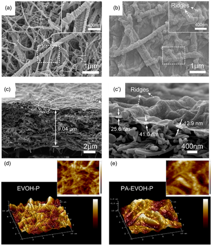
Fibrous supporting layers were commonly used interlayers for fabricating highly rough PA membranes. The fibrous mid-layer was prepared by many methods, that is, wet-laying, vacuum filtration, electrospinning, and so on. Wang et al.105 fabricated a thin ethylene vinyl alcohol copolymer (EVOH) nanofibrous scaffold by wet laying process and subsequent plasma treatment as interlayer (EVOH-P) for preparing TFC membranes. The highly roughen nanofibrous medium obtained a roughness of 206 nm, which served as a rough template for PA layer as shown in Figure 10. The structure of the nanofibrous scaffold and the hydrophilicity treated by plasma together facilitated the formation of PA layer with hierarchical crumpled surface which increased the roughness to 400 nm. Electrospinning was used for fabricating nanofibrous materials for low spinning cost, wide variety of spinnable materials, and controllable technology.106 It was reported that polyacrylonitrile (PAN) nanofibers were electrospun and modified by polydopamine (PDA)/polyethyleneimine (PEI) coatings as support.107 The fibrous substrate was further mineralized with zirconia coatings via hydrolysis of Zr4+. The PA selective layer was conducted on the mineralized support by IP process. The wetting behavior of the support layer was effectively improved by hydrophilic polymer coatings and zirconia decoration. The well hydrophilicity of the interlayer trapped the PIP monomers in the aperture and slow down the movement of PIP in aqueous solution. Meanwhile, the abundant zirconia nanoparticles acted as a template to promote the generation of folds in the PA layer.107 Cellulose fiber with excellent hydrophilicity, wide variety of sources and low cost has been widely applied in membrane fabrication for heavy metal removal and water purification.108 Cellulose nanofibers (CNF), sulfonated cellulose nanofibers and bacterial cellulose nanofibers were used for intermediate to improve TFC membrane structure and performance.109-111 Low et al.109 fabricated a TFC membrane by vacuum filtration CNF and NH2-MIL-53 (Al) MOF nanoparticles on the Nylon substrate as support for IP procedure. The hydrophilic nanofiber provided highly porous substrate and MOF created hilly surface morphology. The roughness of the new interlayer support TFC membrane obtained more than 200 nm which was far more than that of conventional TFC membrane. Zhu and Jin111 prepared nanofilm composed hydrophilic bacterial cellulose nanofibers (BCNs) which reinforced by salts as medium for IP reaction. The strong hydrophilicity of BCNs created a hydration layer which promotes Marangoni convection at water/organic solvent interface. The instability of the interface formed extra area for interfacial reaction, thus produced an arch-bridge structured thin PA active layer.
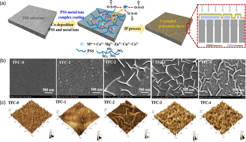
Organic interlayers due to variety and regulated functional groups have been applied for enhancing membrane structure and performance. Wang et al.112 used gelatin as an interlayer and conducted a reverse IP process. The organic monomer was first immersed in the support and reacted with gelatin layer, and then the amine monomer was introduced. The as-prepared membrane achieved crumpled structure as deposition time of gelatin was appropriate. The nanofiltration membrane with nanostrand hydrid morphology could be formed by co-deposition of a macrocycle polyphenol molecule, Noria, and PEI on the support and subsequent IP.113 The amine group on the support acted as a host and the amine monomer played a role of guest. The host-guest heterogeneous interaction significantly altered the IP process forming a typical Turing striped structure on the PA layer. Generally, the formation of crumpled PA membrane by introduction of new interlayer involved many influences as the chemical components, pore size and wettability transferred. Specific chemical modification facilitated the wrinkled morphology as the interaction of functional interlayer with amine monomers regulated by the chemical designs. An striped-like structure membrane was fabricated with APVC support membrane by amination reaction and introducing GO into aqueous solution to participate the IP process.78 Two main factors led to the formation of loose striped morphology: (I) the APVC substrate has strong interaction with amine monomers by electrostatic interaction of hydrogen bond and so on; (II) TMC reacted with amine group on the support layer first, and then connected slowly with the GO to build the crumpled structure. Niu et al.114 proposed a facile coordination-driven assembly strategy to build a poly (sodium 4 styrenesulfonate) (PSS)- metal ions interlayer for high performance TFC membranes (Figure 11). The complex interlayer as nanoscaffold to provide uniform IP platform and as macromolecule to induce the diffusion-driven instability was favorable for creation of thin, defect-free and crumpled PA membrane (Figure 11b,c). TA-Fe3+ interlayer on a polydopamine-modified polyethylene support was used for fabricating a worm-like structure PA layer. The unique morphology was formed by influencing the diffusion of MPD.115 The amine monomer was also affected by the polyphenol intermediate layer prepared by co-deposition of 5,5′,6,6'tetrahydroxy-3,3,3′,3′-tetramethyl-1,1′-spirobisindane (TTSBI) and PEI.116 Nano-pleated structure was formed on the TFC surface and promoted the water permeance. Previous work has indicated that the introduction of a dendrimer porous layer into the IP process enables the formation of a stripe-like PA nanofilm containing ordered nanovoids.117
Novel nanomaterials have also been fabricated as interlayers for TFC membranes. Cheng et al.118 Brush painted MXene nanosheets onto the porous substrates to partially cover the membrane pores, transferring the IP interface from substrate pores to nanosheet surfaces. As the wetting behavior of the supporting membrane and MXene nanosheet differed a lot, which created a patterned “hydrophobic-hydrophilic” zone, a nano crumpled structure morphology on the surface of PA membranes was favored to establish. In addition, the MXene showed high adsorption capacity to PIP molecules for its preferred hydrophilicity, large specific surface area, and confirmed electrostatic interactions and hydrogen bonding between MXene and PIP molecules, which was prone to accumulate PIP for promoting the reaction rate between PIP and TMC and the release of reaction heat. The fast reaction rate and large amount of the heat created a gradient temperature at the interface of water and oil inducing the Marangoni convection and thus caused the instability of the interfacial zone. Based on the above factors, a nano-striped morphology PA layer was generated. Thin- and stripe-structured PA layers were formed on a base GO membrane,119 modified carbon nanotube (mCNT)-deposited substrate120 and g-C3N4 and HNTs co-deposition support121 via IP, respectively. These new carbon-based nanomaterial support layers provided a platform with uniform pore size and rich active groups for the IP process, which plays a vital role in the formation of a highly rough PA layer. Traditional inorganic substrates were obstacle for application by their high price. Lai et al.122 developed an inexpensive support made of large alpha-alumina particles and coated by smaller alpha-alumina particles and carbon nanotubes. The support was smooth and permeable, but the PA layer formed on the coated support showed increased “leaf-like” surface structure. The increased surface area by large “leaf-like” structure facilitated great improvement in membrane flux in solvent nanofiltration. The performance and IP condition of PA membranes with functional interlayer are listed in Table 2.
| Layer | IP condition(optimum) | Roughness | Performance | Ref |
|---|---|---|---|---|
| Gelatin | IP-R 1 wt% PIP/water 0.2 wt% TMC |
Water permeation flux of 33.7 L.m−2.h−1.bar−1 and rejection of 98% for Na2SO4. | [112] | |
Graphitic carbon nitride (g-C3N4) and Halloysite nanotubes (HNTs) |
2.5 mg/mL PIP/water 0.15 w/v% TMC | RMS = 39 nm | Water permeation flux of 20.5 L.m−2.h−1.bar−1 and rejection of 94.5% for Na2SO4. | [121] |
| Bacterial cellulose nanofiber (BCNS) | 0.25 wt% PIP/water 0.49 wt% TMC | Ra = 25.1 nm | Water permeation flux of 42.5 L.m−2.h−1.bar−1 and rejection of 99.1% for Na2SO4. | [111] |
| PSS-metal | 1 w/v% PIP/water 0.1 wt% TMC | RMS = 20.69 nm | Water permeation flux of 22.95 L.m−2.h−1.bar−1 and rejection of 99.3% for Na2SO4. | [114] |
| MXene nanosheet | 1.0 wt% PIP/water 0.1 wt% TMC | Ra = 15.3 nm | Water permeation flux of 27.8 L.m−2.h−1.bar−1 and rejection of 99% for Na2SO4. | [118] |
| Triethylenetetramine (TETA) | 1.5 w/v% PIP/water 0.2 w/v% TMC | Ra = 62 nm | Water permeation flux increased by 60% while salt retention remained stable. | [78] |
| Mineralized nanofiber | 0.5–1% PIP 0.1% TMC | Water permeation flux of 38.2 L.m−2.h−1.bar−1 and rejection of 97.6% for Na2SO4. | [107] | |
| Sulfonated bacterial cellulose (SBC) | 7.5 mg/mL PIP/water 2 mg/mL TMC | Water permeation flux of 32 L.m−2.h−1.bar−1 and rejection of 96% for Na2SO4. | [110] | |
| Porous aromatic PA dendrimer layer | 1.8 w/v% PIP/water 0.1 w/v% CPTC/n-hexane | Water permeation flux of 13.4 L.m−2.h−1.bar−1 and rejection of 98.9% for Na2SO4. | [117] | |
Ethylene vinyl alcohol copolymer (EVOH) nanofibers |
0.2 w/v% PIP/water 0.2 w/v% TMC | Water permeation flux of 42.25 L.m−2.h−1.bar−1 and rejection of 95.97% for Na2SO4. | [105] | |
| Noria, and polyethyleneimine (PEI) | 1.0 wt% PIP/water 0.1 wt% TMC | Water permeation flux of 28 L.m−2.h−1.bar−1 and rejection of 96% for Na2SO4. | [113] | |
| Tannic acid-Fe3+ | 2 wt% MPD/water 0.1 wt% TMC | Ra = 50.1 nm | Water permeation flux of 71.2 L.m−2.h−1 at 0.2 Mpa and rejection of 98.3% for NaCl. | [115] |
| Polyphenol | 1.0 wt% PIP/water 0.1 wt% TMC | Ra = 14.95 nm | Water permeation flux of 23.7 L.m−2.h−1.bar−1 and rejection of 93.4% for Na2SO4. | [117] |
| Inorganic supports α-Al2O3 and carbon nanotube (CNT) | 3.4 wt% MPD/water 0.15 wt% TMC | [122] | ||
| Water template | 1.0 wt% PIP/water 0.1 w/v% TMC | Water permeation flux of 21.3 L.m−2.h−1.bar−1 and rejection of 99.4% for Na2SO4. | [127] |
3.3 Sacrificial template
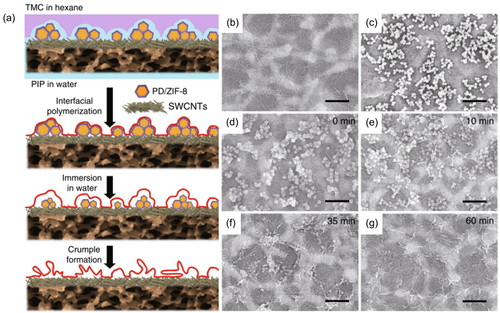
The conventional template method was realized by introducing nanoparticles or preparing a nanofibrous scaffold layer. The sacrificial template method involved formation of template and subsequent removal of the template. In the previous strategy of introducing additives, different salts were added into the aqueous solution, and the template was formed by heating and crystallization. Afterwards, the crystalized salts templates were removed by water rinsing. The sacrificial template method introduced here is to directly prepare a template substrate, then polymerize on the surface of the template to obtain a PA film, and finally conduct a certain route to remove the template to form a PA layer with a wrinkled appearance. Zhu and Zhang et al.46 designed a sacrificial ZIF-L layer for preparing PA membrane. The ZIF-L could be removed by a weak acid solution leaving the PA layer root-like structure. The RMS roughness increased from 7.4 to 60.2 nm for synergetic effect of the addition of PVA and ZIF-L template. Zhu and Jin et al.25 designed a TFC membrane mediated by metal–organic framework nanoparticles (ZIF-8) nanomaterials. The ZIF-8 nanoparticles served as a sacrificial template material preloaded on the porous supporting membrane to produce rough and irregular nanostructures. Then, the IP reaction occurred on the rough substrate surface. After the IP process, these nanoparticles were removed by dissolving in water, leaving a thin PA active layer with a wide range of folds of nanostructures. The schematic diagram was presented in Figure 12 and the membrane surface morphology was crumpled as the nanoparticles removed. This pleated structure significantly increases the effective water penetration area.
3.4 Other strategies
In addition to the above-mentioned strategies for constructing crumpled-structure TFC membranes, some studies have reported other methods, that is, kinetic pathways, in-situ growth nanoparticles or interlayers, and in-situ aqueous phase template for constructing pleated membranes. Zhou et al.123 deconstructed a kinetic pathway of IP to control the morphology of the PA nanofilm as shown in Figure 13. First, a nascent PA nanofilm was fabricated as the main skeleton. Then, a second IP process was conducted by adjusting the monomers' stoichiometric ratio at the new interface. The nodules with controlled size and surface characteristics were established and the formation of hollow nodules increased the overall thickness of the PA nanofilm to ~25.26 nm. Tsuru et al.124 constructed a multilayered PA membranes by two-step IP process as the first spray-assisted IP created a fibrous and planar part PA structure and the second IP contributed to the formation of multilayered ridge-and-valley structures with the size of approximately 1–2 μm in height. He et al.125 demonstrated a high permeable-selective TFC membrane through in situ formed interlayer of chitosan (CS). The CS was added into the amine aqueous and aging for a certain of time. As the diffusion rate of CS was much slow compared to amine monomers during the IP process, a mid-layer was formed by free CS molecules and aged CS nanoparticles. The CS concentration and aging time were controlled for manipulating the membrane surface structure from nodular to vermicular and to a convex structure. Based on the concept of in-situ synthesis, there are researchers who in-situ synthesized silicon oxide through the IP process. Silicon tetrachloride (SiCl4) was involved in the organic solution for preparing TFN membranes. The research verified that silica nanoparticles were embedded in the PA layer and many permeable voids were buried underneath the PA protuberances and overhanging crumples.126 Niu et al.127 fabricated a TFC membrane with 3D surface nanostructures by controlling the force of roller to regulate the residual aqueous solution for interfacial polymerization template. By this route, the surface morphology transferred from leaf-like shapes to ridges. The increased permeable area by the ridges promoted the water permeance.
4 COMPARISON OF THE PERFORMANCE OF CRUMPLED TFC MEMBRANES WITH CONVENTIONAL TFC MEMBRANES
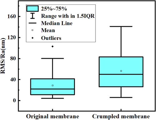
The construction of highly roughened structure in TFC membranes by different strategies showed great effect on membrane performance. The roughness of membrane surface increased to a certain level and the effective surface area arose correspondingly. The summary of membrane surface roughness and separation performance for crumpled membranes based on available references is expressed in Figures 14 and 15. The membrane roughness could increase 881% at most as inorganic salts introduced into the membrane fabrication system.66 The surface area increased from 26.4 to 34.5 μm2. The introduction of nanomaterials into PA layer is the most common method to construct rough membrane. But, due to the small size of the particles and limited incorporation amount in membrane selective layer, the surface roughness varied little compared to other methods. The roughness of most films with nanoparticles added increased about 20%–50% compared with that of membranes without nanomaterials. After summarizing the literatures, it was found that the roughness of the unroughened TFC membranes was generally between 10 and 40 nm, and the surface roughness of the highly rough film prepared by various strategies was in the range of 25–80 nm, up to 140 nm as shown in Figure 14. The average surface roughness of crumpled membranes is 56 nm, and that of conventional membranes is 29 nm, significantly illustrating the effective performance of the mentioned strategies. The increased roughness clearly added more filtration area for the membrane who was in the same apparent area as the conventional membrane.
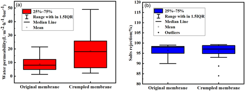
The increase in the surface roughness of the TFC membrane intuitively promoted pure water flux by external filtration area. By summarizing the separation performance of the rough membranes and traditional membranes, it can be found that the average water flux of the crumpled membranes is 2.1 times than that of the traditional membrane and the separation performance are at the same level with average salt rejection 96.4% (Figure 15). It proves that the construction of roughened TFC membrane can improve permeability performance without decreasing the separation performance.
5 ANTI-FOULING PROPERTIES OF CRUMPLED TFC MEMBRANES
Most of the research work on crumpled membranes focused on the “trade-off” effect, and paid little attention to the influence of the fold structure of the membrane surface on membrane fouling. Previous studies have shown that the degree of membrane fouling will increase as the roughness of the membrane increases.35-37 The researchers had found that the ridge-and-valley structured RO membrane was prone to attach foulants and the fouling rate was higher than that of smoother surface membranes.34 Membrane fouling was affected by lots of factors including the hydrophilicity, charge, chemical components and roughness of the membrane surface, operational conditions, as well as the characteristics of the foulants and feed.128 It has been reported that membrane surface roughness may have little effect on biofouling, and some antifouling modifications may lead to rougher membrane surfaces.129-131 Furthermore, Livingston's group132 had found that the high roughness membrane affected the membrane fouling as same as the flat membrane with the same initial flux which means the membrane permeation has a significant effect on the membrane fouling. Commonly, the crumpled membranes show higher water permeance, which lead to serious membrane fouling. The attenuation of permeate flux may not be caused by the wrinkled structure of the membrane surface, but by the high initial flux. Therefore, proper design of TFC membrane with highly rough surface is possible to guarantee the great separation performance with high permeance and good antifouling ability at the same time.
An66 discovered that the highly roughness membrane showed less flux decline and better recovery than flat and relatively low roughness membranes. They conducted in situ optical coherence tomography (OCT) monitoring to validate their hypothesis. The large area of clean-ridge provided effective water permeation channels even when the contaminants covered the valleys. Thus, it is necessary to further study on patterned nano-topography which will improve the filtration performance of nanofiltration membranes. Besides morphology regulation, chemical modification promotes antifouling performance of membrane with increasing superiority. Some additives with ionic groups altered the membrane morphology as well as chemical composition. Taurine with sulfonate group and PEI with amino group combined with TA and TMC to form a zwitterionic striped layer leading to antifouling membrane with high salt separation performance.100 The membrane showed favorable antifouling property in humic acid (HA), SA and bovine serum albumin (BSA) solutions with flux recovery ratio (FRR) > 89.9%. Nanomaterials with unique chemical properties were applied in PA selective layer to regulate membrane morphology and surface free energy for favorable antifouling performance. Liu et al.78 modified the substrate and introduced GO into the selective layer to fabricate PA membrane accompanied by stripe-like surface structure with 75.8% surface roughness increment. The membrane with largest roughness showed best antifouling property for dye solution in long-term experiment for 11 h, because of the chemical bonds between substrate and PA layer improving the stability of the membrane. Layered MoS2 nanosheets with negative charge exhibited excellent antifouling performance when added into PA layer. Though the surface roughness was heightened by the addition of nanosheets, the flux decline was less than the traditional membrane in the presence of BSA and NaCl. The flux attenuation rate reached 9% after 14 h of filtration by 0.01 wt% MoS2-TFN membrane, while that of the TFC membrane was attenuated 15%. The electrostatic force and flat nanosheet surface gave rise to repulsive interaction between the BSA and TFN membrane surface.83 Hydrophilic nanomaterials showed significant anti-fouling performance as hydration layer generated to resist organic pollutants. FBNS embedded membrane showed decreased thickness, increased surface roughness with homogeneous leaf-like structure but excellent fouling tolerance by recovering over 96% pure water permeance in filtrating HA solution.86 TFN membrane with 0.05% NH2-TNTs embedded had higher fouling resistance for BSA due to the lower BSA-membrane adhesive free energy.71 The membrane with NH2-TNTs embedded showed higher fouling resistance compared to TFC membrane with 95% water flux recovery after a simple rinsing process.
6 CONCLUSIONS AND FUTURE PERSPECTIVES
The existing roughness membrane formation principles includes four methods, that is, interfacial nanobubbles effect, template method, diffusion-driven instability and co-solvent effect. In fact, interfacial nanobubbles effect is a special template method with in situ generated nanobubbles act as the template. The co-solvent principle accelerates the diffusion of the water-phase amine monomer to form a miscible intermediate layer, increasing the formation of a widen PA layer. The instability of diffusion drive is to slow down the diffusion rate of amine monomer and forms a difference in diffusion rate. The two mechanisms are just contradictory. It can be seen that the diffusion rate of the reactive monomer has a great influence on the membrane-forming structure, but the relationship between the diffusion rate and the membrane structure is still not clear. There are few reports on the diffusion rate of the oil-phase monomer which has a great influence on the performance of the TFC membrane.
For different mechanisms, the main methods adopted are adding various types of additives, constructing a functionalized intermediate layer, sacrificial templates, multi-stage kinetic reactions, and in-situ formation of nanoparticles, etc. Among these methods, the introduction of additives is the simplest and most widely used method. Various types of additives including polymers, organic co-solvents, inorganic salts, and nanomaterials have tried to add into the PA selective layer generating a rougher structure than the original membrane. However, the removal of additives complicates the membrane production process, and the impure removal may cause secondary pollution during membrane application. For the embedding of nanoparticles, the binding force between nanomaterials and the PA layer has not been studied in detail, especially the inorganic nanoparticles. Their compatibility with the organic PA matrix and their stability in the film have not been thorough reported. Further researches are needed to explore the long-term operation for TFN membranes, the nanomaterials shedding issues and the influence of the shedding on the separation system.
The construction of the intermediate layer assisted to form a TFC membrane with a rough structure and showed good influence on shorten the thickness of the PA layer, which significantly improve the selective permeability performance of the TFC membrane. However, the preparation of the intermediate layer is complicated and difficult to scale up, thus hinders it in industrial application. The intermediate layer consumes additional materials, which increases the cost of the membrane preparation process. The sacrificial template method greatly improves the permeability of the membrane, but the preparation process is multi-program. The bonding force between the surface selective layer and the substrate after removing the template is relatively weak, which easily causes the separation layer to peel or break, thus seems difficult to realize industrial application.
In the future, for further understanding the effect of preparation mechanism on highly rough structures, it is necessary to explore the kinetics of the interfacial polymerization process, especially the influence of the diffusion process on the reaction mechanism, and the influence of supporting membrane pores on the diffusion of monomers. In addition, it is necessary to ensure the existence of associated nanosized voids inside the roughness structures. Otherwise, the membrane thickness of the protruding part will increase, which increases the mass transfer resistance and decreases the membrane permeation flux. Although high roughness shows that it is detrimental to the anti-fouling of the membrane, the anti-fouling properties of some high-roughness pleated membranes still have certain advantages. But effective roughness range against membrane fouling should be further studied. Patterned rough structure and membrane fouling research from the perspective of fluid mechanics are the future research direction of new anti-fouling membranes.
AUTHOR CONTRIBUTIONS
Dan Hu: Conceptualization (lead); writing – original draft (lead). Xiaomin Ren: Writing – review and editing (lead). Hongyan Fu: Validation (lead). Yu Wang: Data curation (lead). Hehe Li: Data curation (equal).
ACKNOWLEDGMENTS
This project has received funding from Scientific Technological Innovation Service Ability Construction-Basic Scientific Research Funding (PXM2020_014213_000017), Research Foundation for Youth Scholars of Beijing Technology and Business University (QNJJ2020-18), National Natural Science Foundation of China (32172340) and Postgraduate Research Ability Enhancement Project (19008021082 and 19008022056).
Biographies

Dan Hu is a researcher of School of Light Industry, Beijing Technology and Business University. PhD degree from Institute of Process Engineering, Chinese Academy of Sciences. Her research interests are coalescence separation of oil/water emulsions; membrane separation includes membrane surface modification and preparation of novel nanofiltration membrane materials. She has worked for water treatment technology for nearly 10 years.

Xiaomin Ren is a master degree candidate of the nanofiltration membrane in the Key Laboratory of Cleaner Production and Integrated Resource Utilization of China National Light Industry, School of Light Industry, Beijing Technology and Business University. Her research interest is surface modification of nanofiltration membrane.

Hongyan Fu is a graduate student in the Key Laboratory of Cleaner Production and Integrated Resource Utilization of China National Light Industry, School of Light Industry, Beijing Technology and Business University. Her research interests are high-performance nanofiltration membrane, water purification, and Li+/Mg2+ separation.

Yu Wang is a graduate student in the Department of Chemical Engineering at Beijing Technology and Business University. She is a researcher in nanofiltration membrane separation technology. Her research interests are devoted to the nanofiltration membrane materials with different properties and the preparation and separation performance of membranes.

Xudong Feng is Assistant Professor of Chemical Engineering Department in Beijing Technology & Business University. He has sponsored two sub-projects of the National Science and Technology Support Program and attended several other projects. His research interests focused on the wastewater treatment technology and equipment, membrane separation technology.

Hehe Li is a researcher of Beijing Key Laboratory of Flavor Chemistry, College of Light Industry Science and Technology, Beijing Technology and Business University. Her research interest is flavor chemistry, especially in Baijiu for 10 years.
Open Research
DATA AVAILABILITY STATEMENT
The data that support the findings of this study are available from the corresponding author upon reasonable request.


