MgO-Template Synthesis of Extremely High Capacity Hard Carbon for Na-Ion Battery
Graphical Abstract
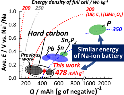
Mg-templated hard carbon as an extremely high capacity negative electrode material for Na-ion batteries is successfully synthesized by heating a freeze-dried mixture of magnesium gluconate and glucose. The hard carbon demonstrates an extraordinarily large reversible capacity of 478 mAh g−1 with a high Coulombic efficiency of 88 % at the first cycle. Owing to the low potential operation, estimated energy density of the full cell is very high.
Abstract
Extremely high capacity hard carbon for Na-ion battery, delivering 478 mAh g−1, is successfully synthesized by heating a freeze-dried mixture of magnesium gluconate and glucose by a MgO-template technique. Influences of synthetic conditions and nano-structures on electrochemical Na storage properties in the hard carbon are systematically studied to maximize the reversible capacity. Nano-sized MgO particles are formed in a carbon matrix prepared by pre-treatment of the mixture at 600 °C. Through acid leaching of MgO and carbonization at 1500 °C, resultant hard carbon demonstrates an extraordinarily large reversible capacity of 478 mAh g−1 with a high Coulombic efficiency of 88 % at the first cycle.
Hard carbon is one of the most promising negative electrode materials for practical Na-ion batteries owing to totally-balanced performance in terms of reversible capacity, working potential, cycle life, and abundant resources.1 Hard carbon consists of mainly two types of nano-sized domains. One is graphitic domain which has a turbostratic structure and random orientation. The other is internal micropores which can be regarded as a void between the graphitic domains. Both domains can electrochemically store sodium, and the nano-sized internal pores act as a predominant active site for electrochemical sodium storage and contribute to a reversible redox activity.2 The internal micropores having a suitable size to accommodate Na clusters are, therefore, of the most importance to design higher capacity hard carbon.3 Recent reports showed that porous and low-density hard carbon materials deliver so higher capacities of 410 mAh g−1[4] and 420–438 mAh g−1.3b, 5 However, preparation of the latter higher capacities materials needs costly process like higher temperature treatment at ≥1900 °C.
Template synthesis of carbon, using inorganic materials, for example, MgO,6 zeolites7 and silica8 as templates, is known as one of the synthesis routes of porous carbon of which internal pore size and its distribution are tunable by modulating template size. Among them, the MgO-template synthesis provides remarkable advantages as follows: 1) MgO is easily leached out by a diluted acid,6 2) pyrolysis of some Mg-containing organic compounds leads to proper nano-sized MgO in carbon matrix, 3) the acid leaching of MgO particles leads to pore formation in the carbon,6 and 4) the size and number of the MgO-templated pores are tunable by selecting Mg-containing starting materials.6 In this study, we uniquely modify the MgO-template method and subsequent post-heat-treatment at 1000–1500 °C and demonstrate a new synthesis of hard carbon powder materials delivering enormously large reversible Na storage capacities beyond 450 mAh g−1.
Magnesium gluconate (Mg(C6H11O7)2, hereinafter, referred to as Mg Glu) was utilized for our MgO template synthesis of hard carbon. Its thermal decomposition was examined with thermogravimetric analysis in Supporting Information, Figure S1. Based on the MgO-template techniques reported in the review article,6 glucose (C6H12O6, hereafter called Glc) was mixed with Mg Glu in different ratios in order to regulate MgO concentration and size of the template. We compared two mixing processes, that is, planetary centrifugal mixing of their powder without solvent and freeze-drying of their aqueous solution, to vary a dispersion state of Mg Glu and Glc. Detailed synthesis procedures are described in the Supporting Information. In a previous report, Kano et al. preheated pure Mg Glu powder at 900 °C and mainly investigated an influence of high post-heat-treatment temperatures (postHTTs) of 1900 and 2400 °C to obtain high-capacity hard carbon.3b, 9 On the other hand, our group reported significant impacts of the preheat-treatment temperature (preHTT) for carbon sources on Na storage capacity of hard carbon.10 Therefore, we first synthesized hard carbon by heating pure Mg Glu powder (without Glc addition) to find an influence from preHTTs of 400, 600, and 800 °C on the resultant hard carbon samples prepared via acid-leaching MgO and post-heating at 1500 °C in an argon atmosphere. Hereafter, names of the hard carbon samples are denoted by HC “preHTT”-“postHTT”(“mixing method” “Mg Glu/Glc ratio”) like HC400-1500(P100:0). Sample abbreviations and synthesis conditions of all the hard carbon samples synthesized in this study are summarized in Table S1. X-ray diffraction (XRD) patterns of the samples are displayed in Figure 1 a. In the XRD data, broad diffraction peaks, observed at relatively low diffraction angles of 2θ=21–23° and assigned to the 002 Bragg diffraction of graphitic domains,11 indicate that all carbon samples have small graphitic domains with wider interlayer spacing between sp2 carbon sheets than 3.354 Å for graphite (see estimated interlayer distances in Table S2). These features are commonly observed for hard carbon.12 Although the interlayer distance is slightly shorter for HC400-1500(P100:0) (3.736(4) Å) than 3.76 Å for the other samples, all the samples have almost the same crystallite size of graphite-like domains with the similar stacking number of carbon sheets.
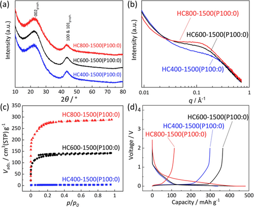
(a) XRD patterns. (b) SAXS patterns. (c) N2 adsorption-desorption isotherms. (d) Initial charge–discharge curves for HC400-1500(P100:0), HC600-1500(P100:0), and HC800-1500(P100:0).
Obvious differences are found in the micropores and surface area of the hard carbon samples. Small-angle X-ray scattering (SAXS) patterns reveal broad humps at the scattering vector, q (=(4π/λ)sinθ, where λ=1.541 Å is the X-ray wavelength and θ is half the scattering angle) of 0.1–0.3 Å−1. The humps arise from micropores in the carbon matrix, including nanometer-sized voids between sp2 carbon planes.13 As shown in Table S2, the calculated size of pores in hard carbon increases from 1.01 to 1.62 nm with increase in the preHTT from 400 to 800 °C. Some micropores are open and can be detected as surface micropores by a N2 adsorption-desorption measurement. All isotherms of the hard carbon samples in Figure 1 c can be classified as Type-I, suggesting the presence of micropores with less than 2 nm in diameter. No mesopores are confirmed in the pore size distribution data (see Figure S2). Specific surface area of the hard carbon calculated with Brunauer–Emmett–Teller (BET) theory increases from 10.9 to 839 m2 g−1 with elevated preHTTs. These results indicate that raising the preHTT results in growth of MgO-template particles and larger size and number of open micropores after the MgO removal and post-heating.
Electrochemical Na storage properties of the hard carbon samples are compared in Figure 1 d. Similar to the hard carbon materials reported so far,14 the hard carbon electrodes exhibit typical initial charge–discharge curves of Na ∥ hard carbon cells; a sloping voltage region above 0.15 V and a plateau region below 0.15 V vs. Na. The initial desodiation capacities of the HC400-1500(P100:0), HC600-1500(P100:0), and HC800-1500(P100:0) samples are 299, 365, and 114 mAh g−1 with initial Coulombic efficiencies of 88, 83, and 24 %, respectively (Table S3). Low Coulombic efficiency results from massive electrolyte decomposition and solid electrolyte interphase (SEI) formation15 on the large surface area of hard carbon as observed for HC800-1500(P100:0). In spite of large specific surface area (484 m2 g−1), HC600-1500(P100:0) delivers the high Coulombic efficiency. The fact suggests that surface micropores formed in the 600 °C sample are almost closed against the electrolyte liquid. We believe that such conflicting results originate from the size difference between N2 molecules and electrolyte (solvated sodium ion).3a
For further tuning size and concentration of MgO templates, we employed diluting Mg Glu with Glc because we studied Glc-derived hard carbon free from MgO template.10b The mixtures of Mg Glu and Glc were prepared through a freeze-drying method including processes of dissolving in water and freezing by liquid N216 to ensure homogeneous mixtures of the organic compounds without thermal decomposition as drawn in Figure 2 a. We hereafter denote the method as “freeze-drying” and just mechanical mixing of the starting materials (Mg Glu and Glc) as “powder-mixing”. The names of hard carbon samples are denoted by HC“preHTT”-“postHTT”(F“Mg Glu/Glc ratio”) and HC“preHTT”-“postHTT”(P“Mg Glu/Glc ratio”), respectively.
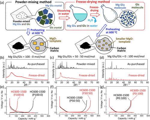
(a) Schematic illustration for the two mixing procedures for preparation of the mixtures of Mg Glu and Glc. Comparison of XRD patterns for the powder-mixed (including non-mixed as-purchased powder) and freeze-dried precursors at the Mg Glu/Glc ratios of (b) 100:0, (c) 50:50, and (d) 0:100 mol/mol. Initial charge–discharge curves of the Na cells for the corresponding hard carbon samples prepared via different precursor-preparation processes at the Mg Glu/Glc ratios of (e) 100:0, (f) 50:50, and (g) 0:100 mol/mol, followed by preheating at 600 °C, acid-treatment, and post-heating at 1500 °C.
Effect of the freeze-drying method was examined from the XRD data of pure Mg Glu, pure Glc, and their mixture at the Mg Glu/Glc ratio of 50:50 mol/mol (Figure 2 b–d), which were used as precursors for preheating. In the pure Mg Glu case (Figure 2 b), as-purchased Mg Glu powder represents a lot of sharp diffraction peaks attributed to Mg Glu crystals17 whereas the freeze-drying method results in quite broad peaks at 20° and ca. 38°. A similar trend is observed in the XRD patterns of Mg Glu/Glc mixtures (Figure 2 c). In contrast, sharp diffraction peaks are observed for pure Glc regardless of the mixing methods (Figure 2 d). These results suggest that the freeze-drying enhances dispersion of Mg Glu and suppresses its crystallization except or the pure Glc cases.
Hard carbon samples were synthesized from these freeze-dried starting materials through preheating at 600 °C, acid-treatment, and post-heating at 1500 °C. Similar to the hard carbon samples in Figure 1, interlayer distances, pore size, BET surface area, and particle morphology for the carbon samples were examined by using XRD, SAXS, N2 adsorption/desorption, SEM, and TEM measurements, and the results are summarized in Figure S3–S8. Regardless of the mixing methods and the Mg Glu/Glc ratio, the resultant carbon samples show similar particle sizes and broad XRD peaks, which confirms formation of hard carbon as shown in Figure S3–S6. Figure 2 e–g compares initial charge–discharge curves of the hard carbon samples prepared via the different precursor-preparation methods. By comparing the two methods, obvious differences in reversible capacities are found for the pure Mg Glu and the mixture cases. Whereas, Glc-derived hard carbon samples deliver almost the same capacities of 330–340 mAh g−1 with high initial Coulombic efficiency of ca. 90 % agreeing with no obvious differences in the XRD patterns for the precursors in Figure 2 d. In the case of pure Mg Glu, HC600-1500(P100:0) and HC600-1500(F100:0) deliver initial reversible capacities of 365 and 123 mAh g−1 with Coulombic efficiency of 83 and 31 %, respectively (Figure 2 e). The freeze-drying results in the much-increased irreversible capacities which correlates to enlarged BET surface area of the hard carbon samples (Figure S8). Unlike the two cases of pure starting materials, the mixture-derived hard carbon samples through powder-mixing and freeze-drying (HC600-1500(P50:50) and HC600-1500(F50:50), respectively) deliver extremely large reversible capacities of 418 and 478 mAh g−1 with high efficiencies of 86 and 88 %, respectively, at the first cycle. The freeze-drying for the Mg Glu and Glc mixture results in enhancement of both reversible capacity and Coulombic efficiency compared to those in the powder-mixing. To the best of our knowledge, both the high efficiency and large reversible capacity of 88 % and 478 mAh g−1, respectively, in the potential range from 2 to 0 V are totally superior to hard carbon materials which were reported to date. Including the other Mg Glu/Glc ratios of 75:25 and 75:25 mol/mol, the largest reversible capacities are successfully demonstrated by the hard carbon samples derived from the 50:50 mol/mol mixtures regardless of the mixing methods as shown in Figure S6e and S8. Also, cycle test in Na cells confirms that all of hard carbon electrodes shows acceptable capacity retention for rechargeable battery application (see Figure S6f).
Since obvious differences between the two precursor-preparation methods are observed in the pure Mg Glu precursors, here, we discuss their effects on MgO templates formed by the preheating Mg Glu. XRD patterns of the preheated as-purchased and freeze-dried Mg Glu at 600 °C (HC600(P100:0) and HC600(F100:0), respectively) are shown in Figure 3 a. HC600(P100:0) shows sharper diffraction peaks at 2θ=ca. 43° and 62° attributed to larger MgO crystallites compared to those in HC600(F100:0). Crystallite sizes of the MgO particles estimated by Scherrer's equation are 1.65(2) and 1.10(9) nm for HC600(P100:0) and HC600(F100:0), respectively. The TEM image of HC600(P100:0) also directly evidences the large lattice-fringe domains in 1–5 nm size of MgO crystallites with d200,MgO=0.207(5) nm (Figure 3 b), while the MgO domains with d200,MgO=0.20(5) nm are smaller in HC600(F100:0) (Figure 3 c). The feature is clearly confirmed in the dark-field TEM images in Figure S7.
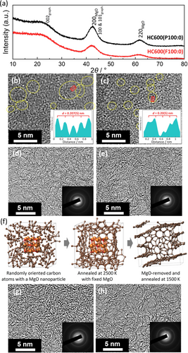
(a) XRD patterns and (b,c) TEM images of (b) HC600(P100:0) and (c) HC600(F100:0). Dotted yellow circles indicate lattice fringes of MgO nanoparticles. Inset panels represent averaged line-profile for the MgO nanoparticles in the red square regions. (d,e) TEM images and SAED patterns of (d) HC600-1500(P100:0) and (e) HC600-1500(F100:0). (f) Snapshots of MgO/carbon composite structures and MgO-removed one calculated by first-principles molecular dynamics and drawn by the program VESTA.19 Brown, orange, and red spheres represent carbon, magnesium, and oxygen atoms, respectively. TEM images and SAED patterns of (g) HC600-1500(F0:100) and (h) HC600-1500(F50:50).
After the subsequent acid-leaching MgO and post-heat treatment at 1500 °C, the MgO crystallites completely disappear in the TEM images of HC600-1500(P100:0) and HC600-1500(F100:0) (Figure 3 d,e). According to the previous report,6 MgO nanoparticles can be partly leached away by HCl aq. treatment, and then residue MgO can be completely removed by reduction of MgO with carbon and evaporation of resultant Mg metal (b.p.=1090 °C18) during the 1500 °C post-treatment, leading to formation of similar size of empty pores in the carbon. The pore size is larger in HC600-1500(P100:0) (Figure 3 d) compared to HC600-1500(F100:0) (Figure 3 e), but the pores are not so clearly distinguishable from the disordered carbon matrix in the TEM images.
To understand the role of MgO nanoparticle and elucidate the nanoporous structures of hard carbon, we employed first- principles molecular dynamics calculations (see detailed calculation conditions in Supporting Information). Estimated equilibrium structures of MgO-templated carbon and MgO-removed one are shown in Figure 3 f. The retained carbon network during simulated annealing calculation at 1500 K indicates the reasonable stability of the empty pore surrounded with the carbon matrix even after MgO removal, which agrees with the reported results on micro/meso porous carbon materials.6 The results of XRD (Figure 3 a) and SAXS (Figure S8) also support size analogy between the MgO crystallite in the preheated precursor and the pore in hard carbon bulk. Thus, the pores in the resultant hard carbon are templated with the MgO nanoparticles which enables to control the pore size by selecting Mg Glu/Glc ratios, preHTTs, and mixing conditions of starting materials.
From the viewpoint of local structures of hard carbon samples, effects of Mg Glu/Glc ratio are discussed with TEM images in Figure 3 e,g,h. HC600-1500(F100:0) (Figure 3 e) and HC600-1500(F50:50) (Figure 3 h) include the graphitic domain consisting of mainly three-layered stacking in the porous structure while HC600-1500(F0:100) (Figure 3 g) is composed of four or more stacked carbon-sheets in the dense structure. From the XRD data, the use of pure Mg Glu and Mg-rich mixtures results in the smaller stacking number of the carbon sheets (see Figure S8b). Since highly graphitized domains, which consist of flat and thick stacking of more than 5 sheets with narrow interlayer space, are electrochemically inactive for Na storage,20 moderately disordered graphite-like structures are believed to contribute the capacity increase as reported elsewhere.20, 21
We found that the Mg Glu/Glc ratio influences the stacking number of carbon sheets and the size of MgO particle as a template to form pores in hard carbon. Although the freeze-drying method leads to homogeneously dispersed MgO/carbon sources, the resultant hard carbon derived from Mg-rich sources has the small stacking number of carbon sheets and open pores against electrolytes, inevitably resulting in a large irreversible capacity and a small reversible capacity. Due to these interacted factors, the 50:50 mol/mol freeze-dried mixture induces the formation of unique hard carbon material delivering the extremely large capacity with high Coulombic efficiency.
By using the 50:50 mol/mol freeze-dried mixture and for achieving higher-capacity sodium storage, preHTT was optimized again as was done for the as-purchased Mg Glu powder precursor in Figure 1 (see structure and morphology analysis results for the synthesized hard carbon samples in Figure S9-S11 and Table S4). Initial charge–discharge curves of the hard carbon electrodes are shown in Figure 4 a and Table S5. Among the samples, HC600-1500(F50:50) delivers the largest reversible capacity of 478 mAh g−1. The second largest capacity of 469 mAh g−1 is obtained for HC650-1500(F50:50) and the smallest capacity is for HC400-1500(F50:50), which is a different trend from the pure Mg Glu cases in Figure 1 d. Initial Coulombic efficiencies of the samples are ca. 88 % except for that of HC800-1500(F50:50) (84 %), which can be explained by the largest BET surface area and electrolyte decomposition on the particle surface, resulting in the largest initial irreversible capacity (see Table S4 and S5). We noted that no formation of MgO crystals is confirmed by the XRD pattern of the preheated precursor at 400 °C (HC400(F50:50)) (Figure S12). TEM-EDS spectra evidence complete removal of the Mg-containing components only for HC400(F50:50), while MgO nanoparticles remained in the 550–800 °C samples after acid leaching. In the latter samples, complete removal of Mg ingredient from the carbon matrix is achieved through the reduction of MgO into Mg metal and volatilization during post-heating (see Figure S10 and S13). Consequently, no formation of the MgO template in HC400(F50:50) results in the smallest capacity of 294 mAh g−1. Noted that we have confirmed that the acid leaching process is necessary to obtain the large capacities even though MgO is removed through the post-heating process (Figure S14).
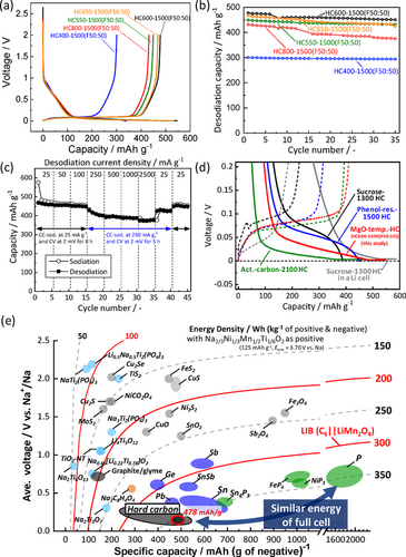
(a) Initial charge–discharge curves. (b) Cycle performance of HC400-1500(F50:50), HC550-1500(F50:50), HC600-1500(F50:50), HC650-1500(F50:50), and HC800-1500(F50:50). (c) Rate performance of HC600-1500(F50:50). (d) Average voltage (vs. Na) and energy density versus gravimetric capacity for various negative electrode materials for Na-ion batteries. The estimated energy density as full Na-ion cells is also shown with P2-Na2/3Ni1/3Mn1/2Ti1/6O2 as a positive electrode.25
In Figure 4 a, the capacity ratio in the lower-potential plateau than 0.15 V is as high as ca. 85 % of the entire desodiation capacities except for HC400-1500(F50:50) (72 %) as summarized in Table S5. In the plateau region, two sodiation processes; i.e., sodium intercalation into interlayer space of turbostratic graphite-like domains and sodium filling accompanied by Na clustering in pores (or void), were proposed.1b, 3c, 21b, 22 In the former case, the theoretical intercalation capacities corresponding to the formation of NaC24, NaC8, and NaC6 are 92, 279, and 372 mAh g−1, respectively.20, 21c Actually, the plateau capacities for HC600-1500(F50:50) and HC650-1500(F50:50) are ca. 400 mAh g−1, which is larger than the theoretical values.
Further, we considered Na clustering in closed micropores and conducted an ex-situ solid-state 23Na magic angle spinning (MAS) NMR measurement for sodiated and desodiated HC600-1500(F50:50) electrodes (Figure S15). The observed signal located at 1030 ppm for the sodiated sample does not originate from metallic sodium dendrite in/on hard carbon (1128 ppm23) and is successfully assigned to quasi-metallic sodium according to the peak assignments reported in the literatures.3c, 10c, 23
Based on the results and estimated closed-pores volume as well as maximum sodiation capacities (see detailed data and discussion in Table S6 and Figure S16–18), both Na intercalation and Na clustering reactions are expected to contribute to the high capacity sodium storage in the voltage plateau region.24 The extremely high capacity hard carbon has opened a door towards new material design of high-capacity Na storage carbons.
Figure 4 b displays cycle stability of the hard carbon electrodes in Na cells. All the hard carbon electrodes in Na cells exhibit acceptable capacity retention except for HC800-1500(F50:50), of which gradual capacity decay is probably due to electrolyte decomposition on the surface as mentioned above. Among all hard carbon samples, HC600-1500(F50:50) sample demonstrates the highest capacity of 478 mAh g−1 with good capacity retention at 25 mA g−1. Although reversible capacity decreases to ca. 400 mAh g−1 at a higher sodiation current density of 250 mA g−1, HC600-1500(F50:50) exhibits excellent desodiation rate performance as shown in Figure 4 c. From the extremely large capacity mainly obtained in the voltage plateau region, low sodiation potential close to 0 V vs. Na+/Na was anticipated and concerns metallic Na plating. However, from magnified charge–discharge curves in Figure 4 d, we confirmed that the sodiation potential plateau is located around 0.05 V vs. Na and lower, which is higher than that of the post-heated activated carbon at 2100 °C in a Na cell5a and sucrose-derived low postHTT hard carbon in a Li cell.3d The 23Na MAS NMR signal at the lower-frequency shift of 1030 ppm for sodiated HC600-1500(F50:50) also implies more ionic state of sodium atoms compared to those reported for the sucrose-derived hard carbon at the postHTT of 2000 °C (1114 ppm).10c Therefore, the potential risk of metal plating for HC600-1500(F50:50) is lower than high postHTT hard carbon as well as high-capacity low-postHTT hard carbon in a Li cell. Hard carbon preparation at the moderately high postHTTs of 1300–1600 °C leads to reduced risk of Na plating as well as cost reduction compared to high postHTTs of 1800–2400 °C. Even at the moderately high postHTT, heat treatment of the freeze-dried Mg Glu and Glc mixture has produced extremely high-capacity hard carbon as a negative electrode material for Na-ion batteries.
The energy density of a Na-ion full cell with the hard carbon negative electrode and P2-Na2/3Ni1/3Mn1/2Ti1/6O2 as a positive electrode material25 was calculated and compared in Figure 4 e (see the simulated voltage curves of the full cell in Figure S19). Surprisingly, the large capacity (478 mAh g−1) and the low working potential (ca. 0.085 V vs. Na) for the hard carbon lead to the high energy density of 358 Wh kg−1, which is almost the same energy density for phosphorous materials delivering ca. 2000 mAh g−1.26 Furthermore, the gravimetric capacity density of 478 mAh g−1 corresponds to formation of NaC4.7 at the fully sodiated state. The sodium content is nonstoichiometric and much higher than stoichiometric lithium content in the graphite electrode (LiC6) at the fully charged state of the Li-ion full cell. When the hard carbon electrode (478 mAh g−1 and 0.085 V vs. Na+/Na corresponding to 0.385 V vs. Li+/Li) is imaginarily combined with a standard positive electrode of LiCoO2 (160 mAh g−1 and 3.8 V vs. Li+/Li) as a hard carbon∥LiCoO2 full cell and compared to that for the graphite electrode (specific capacity of 372 mAh g−1 and working potential of 0.1 V vs. Li+/Li), theoretical energy densities of the imaginary hard carbon∥LiCoO2 cell and graphite∥LiCoO2 cell are almost the same values of ca. 409 and 414 Wh kg−1, respectively. If we do not take into account weight of positive electrode in full cell, the +19 % increase of energy density (Wh kg−1) can be achieved by the hard carbon (see Figure S20). The extremely higher capacity of our developed hard carbon will enable to overcome the general issue of lower voltage operation and lower energy density of Na-ion cell originating from the difference between Eo(Na+/Na) and Eo(Li+/Li) compared to those of Li-ion.
In conclusion, novel hard carbon materials are synthesized via a MgO template technique and demonstrate unusually large reversible capacities of 478 mAh g−1 with initial Coulombic efficiency of 88 % in aprotic Na cells. Systematic studies on the synthesis conditions reveal that the freeze-drying process, including mixing starting materials of Mg Glu and Glc in solution, enhances homogeneous dispersion of the MgO sources. Once MgO nanocrystals are formed during the preheating at 600 °C, MgO acts as a template to form nano-sized pores in the resultant hard carbon during the post-heating at 1500 °C. Large total volume of the nanopores (or nano-sized voids) and surrounding thin graphitic layers with a wide interlayer space are of mutual importance for the high-capacity sodium storage in hard carbon. Owing to the extremely high capacity of 478 mAh g−1 with a low-potential operation (ca. 0.085 V vs. Na), the energy density of the theoretical full cell with the hard carbon negative electrode and P2-Na2/3Ni1/3Mn1/2Ti1/6O2 as a positive electrode material is calculated to be as high as 358 Wh kg−1, which is comparable to that for phosphorous materials delivering ca. 2000 mAh g−1. Because of the nonstoichiometric Na storage content (NaC4.7 corresponding to 478 mAh g−1), further higher capacity Na storage is expected for future hard carbon materials.
Acknowledgements
The authors are grateful to Dr. Toshinari Ichihashi and Prof. Yasushi Idemoto at Tokyo University of Science (TUS) for TEM measurements, to Ms. Yoko Tanaka for experimental supports, and to Prof. Hidenori Otsuka and his laboratory members at TUS for experimental assistance. This work was partly supported by MEXT program “Elements Strategy Initiative to Form Core Research Center” (Grant No. JPMXP0112101003) and by JST through CONCERT-Japan program of SICORP (Grant No. JPMJSC17C1).
Conflict of interest
The authors declare no conflict of interest.


