Feedback and Communication in Active Hydrogel Spheres with pH Fronts: Facile Approaches to Grow Soft Hydrogel Structures
Abstract
Compartmentalized reaction networks regulating signal processing, communication and pattern formation are central to living systems. Towards achieving life-like materials, we compartmentalized urea-urease and more complex urea-urease/ester-esterase pH-feedback reaction networks into hydrogel spheres and investigate how fuel-driven pH fronts can be sent out from these spheres and regulated by internal reaction networks. Membrane characteristics are installed by covering urease spheres with responsive hydrogel shells. We then encapsulate the two networks (urea-urease and ester-esterase) separately into different hydrogel spheres to devise communication, pattern formation and attraction. Moreover, these pH fronts and patterns can be used for self-growing hydrogels, and for developing complex geometries from non-injectable hydrogels without 3D printing tools. This study opens possibilities for compartmentalized feedback reactions and their use in next generation materials fabrication.
Introduction
Living systems have the capability to filter signals, process information, communicate, and form patterns via reaction-diffusion fronts, as controlled by feedback-controlled reaction networks with spatiotemporal organization.1, 2 These processes rely on exchange and correlation of signaling molecules, such as ions, hormones, and/or neurotransmitters.3 An ultimate result is the construction of living architectures, as for instance seen in morphogenesis.4 Such biological phenomena are a source of inspiration for the field of chemical reaction network (CRN)-based, life-like materials, even though synthetic approaches can only capture parts of the complexity found in living systems.5 In general, approaches in this direction exploit chemical complexity in the form of CRNs to control spatial and temporal organization in materials and systems.6-11 Inspired by nature, man-made CRNs have been demonstrated in cell-free systems using peptide,12 protein,13 DNA strand displacement,14 DNA-RNA,15, 16 and enzymatic reaction networks.17, 18 Important features such as threshold sensing,19 bistability,20, 21 oscillations,22-24 and pattern formation25 could be shown on a molecular level. Building on this, CRNs were combined into materials to control physiochemical responses,26, 27 capsule permeability,28, 29 patterns,30 communication,31-34 gating,35 chemotaxis,36 diffusiophoresis,37, 38 and hydrogel formation.39-44 Hence, feedback-driven CRNs can offer a great control on a molecular scale, but their behavioral diversification demands for a proper sketch of the kinetics and network topology, and the step from molecular systems to materials continues to be a significant challenge.
The most complex behavior in man-made CRNs can at present be obtained in DNA, protein and peptide-based CRNs, due to facile molecular programming and partly predictable behavior.24, 45 Yet, it may be argued that such CRNs may face some limitations in a facile higher-level application in the materials field due to some limitations in scalability, and also because responsive materials have been designed in the past decades to a very high level to operate with comparably simple triggers in a very robust manner.7 pH-switchable self-assemblies and materials are one eminent contender. In fact, pH feedback-driven CRNs have emerged in recent years as versatile tools to organize self-assemblies in time and to make transient materials.18, 43 Such systems also benefit from their relatively simple analysis using pH. One prominent pH-type CRN uses the urea-urease driven pH feedback system that has been analyzed in homogeneous solution, or under confinement both experimentally and theoretically to exhibit feedback, front propagation, as well as bistable and oscillatory behavior.46-50 Recently, we demonstrated more complex dual network systems (urea-urease/ester-esterase) in solution,41 or under the confinement into layers51 as a strategy towards new behavior in a stirred supernatant solution. In the context of this research, we hypothesized that fundamentally new and more complex behavior of CRNs may be accessible by exploiting the compartmentalization of antagonistic enzymatic networks (urea-urease/ester-esterase) into spatially organized hydrogel spheres, and by focusing on systems in non-stirred condition so as to add reaction/diffusion components as additional system component to complexify the overall behavior.
Therefore, we herein introduce urea-urease or more complex urea-urease/ester-esterase CRNs that are compartmentalized into spheres, core/shell spheres, and patterns of spheres, to generate and manipulate pH fronts and pH-patterns.47 Although the urea-urease network50, 52, 53 has been investigated previously in homogeneous solutions, we herein focus on compartmentalized systems with spatial heterogeneities. By using pH-sensitive dyes, the systems become convenient to understand as the developing pH fronts can be visualized in real time. Depending on the constitution of the systems, we identify not only tunable pH front speeds, but also unravel non-linear response (damping), membrane activity in core–shell spheres and inter-sphere communication on a larger length scale (Figure 1). Furthermore, we also demonstrate that the new behavior of the systems with reaction/diffusion54-56 components can be exploited on a materials level for self-growing materials. We showcase this for the growth of gel objects with various geometries based on a peptide hydrogel that can otherwise not be 3D printed by classical 3D printing extrusion methods due to its fragile nature.
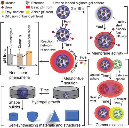
A roadmap from pH front chemistry to systems and materials design. Studies comprise enzymatic reaction networks encapsulated in single spheres to induce and regulate pH fronts and identify non-linear phenomena, installing a membrane activity by addition of pH-responsive gel shells to core–shell spheres, inter-sphere communication between spheres containing antagonistic enzymes, and self-synthesizing 2D and 3D hydrogel structures as an alternative to 3D printing tool.
Results and Discussion
At the outset, to reach patterns and pH fronts, we immobilized urease into Ca2+-crosslinked alginate gel spheres (20 μL, radius (R)=1.3±0.1 mm, details in the experimental section). Rheology of the Ca2+-crosslinked alginate gel shows a sufficiently strong gel matrix (Figure S1), and enzyme leakage does not occur during the experimental time period (Figure S2). To study in detail the comparably simple urea-urease CRN, we immersed these spheres into a fuel solution containing urea (300 mM at 10 mM Na3citrate/citric acid buffer (Na3C/CA; pH 3.5 as start pH)) and used bromocresol purple (BCP; 0.2 g L−1) as an optical read-out with a switching value at pH 6–8. The reaction starts when the fuel urea diffuses inside the gel sphere and is converted by urease to NH3 (and CO2). Consequently, a high concentration of OH− ions locally accumulates at the surface and inside the gel sphere, which generates a basic pH front that travels throughout the fuel solution with time (Figure 2 a). An optical analysis allows to determine the initial speed of the pH front (at t≈0) and the average front speed (between t=10–60 min).
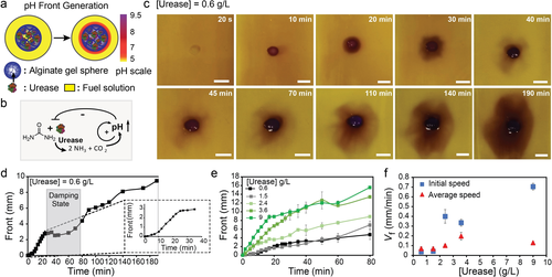
Non-linear network responses of urease-loaded gel spheres in urea/Na3C/CA solutions. a) A pH front when placing a urease-loaded alginate gel sphere into a solution containing urea (300 mM) at a starting pH of 3.5 (10 mM Na3C/CA). The pH color scale is a guide to the eye. b) Urea-urease network topology. c) Time-lapse photographs of the basic pH front from compartmentalized urea-urease reaction network, highlighting the non-linear damping phenomenon (0.6 g L−1 urease). d) pH front propagation for a single experiment with urease gel sphere (0.6 g L−1 urease) clearly presenting initial sigmoidal signature and later damping phenomenon. e) pH front propagation with various urease concentrations (average of 2–3 repeats). f) Initial (t≈0 min) and average (from t=10–60 min) pH front velocities as a function of the urease concentration. Experimental conditions: 20 μL sodium alginate (4.5 wt %); respective enzymes concentrations; Fuel solutions: 300 mM urea, 10 mM Na3C/CA (pH 3.5), and 0.2 g L−1 BCP. Scale bars: 5 mm. Table S1 lists the values of initial and average speeds.
To understand the occurring regimes, it is important to recall that urease has a bell-shaped pH-dependent activity curve with a maximum activity at pH 7, flanked by two pH areas of substantially lower to almost zero activity (Figure S3a). Hence, when starting from an acidic pH 3.5, the NH3 production can exert first positive and ultimately negative feedback on the enzyme activity (Figure 2 b). The basic pH front becomes stable, and sustains if, and only if, the rate of NH3/OH− production by the active gel sphere is greater than its consumption into the surrounding acidic fuel sink (10 mM Na3C/CA). The generation of the pH front and its traveling speed shall be proportional to the CRN reactivity, and thus the enzyme concentration. Therefore, we determined both initial and average speeds to estimate the relative activity of the CRN compartmentalized in the gel sphere as a function of urease concentrations. Figure 2 c,d demonstrates an exemplary network response at low urease concentration (0.6 g L−1). A stable basic pH front, generated after a few minutes (ca. 5–10 min), travels initially through the fuel solution. Later, it starts to be annihilated at 40 min and then reappears and reaccelerates at 110 min with the progress of reaction. This reflects a non-linear damping signature which is in good agreement with its network topology that consists of a positive feedback and a coupled negative feedback module (Figure 2 b). The damping is caused by the consumption of urea and the negative feedback of the generated basic environment (see Figure S3a for pH-dependent urease activity). Subsequent Na3C/CA equilibration during the damping period (ca. 40–70 min), even though in an inhomogeneous, non-circular manner, causes a slight lowering of the pH (BCP switches at pH 6–8). Together with diffusive resupply of urea, the confined urease picks up the reaction speed again. Hence, in contrast to homogeneous stirred solutions investigated earlier, the compartmentalized enzymatic reaction network hub is controlled by diffusion processes.51
Owing to some unavoidable non-uniformity in the gel sphere shape and enzyme distribution, the traveling front is not always perfectly circular (Figure S4), but averaging repeats (2–3 times) minimizes the error and provides consistent data even for such complex systems (Figure S5). The non-uniform pH front becomes more prominent when the network gets inhibited by the inherent negative feedback loop. The fundamental feedback modules (e.g., positive, and negative feedbacks) are clearly visible when plotting the traveling distance of the pH front vs. time (Figure 2 d). The initial sigmoidal curve supports the fast autocatalysis (positive feedback, Figure 2 d, ca. first 15 min) and then a damping phenomenon signifies the coupled negative feedback module. Figure 2 e compares the front propagations (average of 2–3 measurements) for various enzyme concentrations (Figure S6). Due to the averaging, the damping phenomenon becomes less pronounced compared to the individual measurements. The reaction speed in terms of pH front speed levels off at larger distances for most of the experiments due to the volumetric nature of the expansion.
Clearly, the initial speed and the average speed of the pH front are a function of the urease concentrations. Three different regimes can be observed (Figure 2 f). First, in the low concentration regime of urease (i.e., <2 g L−1), both the initial and average speeds of the pH front are low, implying a low network reactivity inside the gel sphere. Secondly, at relatively higher concentration of urease (i.e., 2–4 g L−1), the moderate initial and average speeds of the pH front suggest an optimum balance of positive/negative feedbacks and diffusion of educt and product, allowing the system to stay at the high activity regime in its bell-shaped pH curve. This results in a stable propagating pH front. Third, at elevated urease concentration (i.e., 9 g L−1), the high initial speed of the pH front signifies an initial high network reactivity inside the gel sphere. This produces excessive quantities of OH− ions, which then induce significant negative feedback (high pH) to the system that cannot be compensated by influx of Na3C/CA and more urea. As a result, the average speed of the pH front at later stages drops significantly (Figure 2 f).
We hypothesized that a further self-regulation could be possible by creating a more complex network via the addition of an ester-esterase reaction module into the urea-urease spheres (Figure 3 a). Individually, the ester-esterase network and its principal operation in hydrogel spheres was confirmed by a reference experiment (Figure S7). The esterase has a low activity at acidic pH and reaches high activity at medium to high pH (Figure S3b). Based on the network topology shown in Figure 3 b, we surmised that the esterase could have accelerating, stabilizing or destructive influence on the basic pH front. A high reactivity of the ester-esterase module producing high quantities of H3O+ ions was expected to prevent a basic pH front and inhibit the overall network response. In contrast, a low to moderate ester-esterase reactivity may yield an optimum concentration of H3O+ to stabilize the overall basic pH front propagation by maintaining the urea-urease reaction closer to the center of its bell-shaped activity profile, and thus prevents a drift and loss of activity at very high pH.

Non-linear network responses of urease/esterase gel spheres in urea/EA/Na3C/CA solutions. a),b) Experimental setup and urea-urease/ester-esterase network topology. The pH color scale is a guide to the eye. c),d) Time-lapse photographs of pH fronts from compartmentalized urea-urease/ester-esterase reaction networks (0.6 g L−1 urease, (c) 5.4 and (d) 12 g L−1 esterase). e) pH front propagation for various esterase concentrations for urease/esterase-loaded spheres (0.6 g L−1 urease; average of 2–3 measurements). f) Initial (t≈0 min) and average (from t=10–60 min) pH front velocities as a function of the esterase concentration. Positive and negative feedback to the pH front depend on esterase concentration against a fixed urease concentration of 0.6 g L−1. Experimental conditions: 20 μL sodium alginate (4.5 wt %) with respective enzymes mixtures; Fuel solutions: 300 mM urea, 1.00 M EA, 10 mM Na3C/CA (pH 3.5), and 0.2 g L−1 BCP. Scale bars: 5 mm. Table S1 lists the values of initial and average speeds.
To confirm these principles, we fixed the urease concentration at 0.6 g L−1 (the damping situation from above, Figure 2 c) and varied the esterase concentration from 0 to 12 g L−1 in the gel sphere (Figure S8). Urea and ethyl acetate (1 M EA) serve as fuels. Figures 3 c & d display the pH front propagation at 5.4 and 12 g L−1 esterase at fixed urease concentration (0.6 g L−1). Strikingly, 5.4 g L−1 esterase indeed stabilizes the pH front, whereas 12 g L−1 esterase clearly reveals damping at 40 min and suppression at longer time (Figure 3 c,d). Figure 3 e,f summarizes the real time pH front propagation and the traveling speeds for all binary enzymes system. Figure 3 f shows that the presence of esterase at low to medium concentration (<7.2 g L−1; at fixed urease (0.6 g L−1)) clearly accelerates both the initial and the average speeds of the pH front compared to the reference gel sphere without esterase (urease, 0.6 g L−1, Figure 2 c). A synergistic network response occurs, because the concentration of OH− ions produced by the urease network can be compensated near optimally with H3O+ ions produced by the esterase network. This maintains an ideal pH window (pH 6–8) for the system to retain all the subnetwork reactions at high level. This observation signifies the positive feedback by the esterase reaction network to the basic pH front of the overall system at this concentration regime. Second, at high esterase concentration (12 g L−1; at fixed urease (0.6 g L−1)), the low initial and average speed of the pH front generated by the gel sphere represents an inhibition effect to the overall system response as the antagonistic esterase network produces excessive quantities of H3O+ ions and overcompensates the urease activity.
Next, we sought to program a physicochemical membrane activity over the compartmentalized urea-urease spheres. Membrane activity is a mechanism usually seen in materials and living systems to control functionalities.57, 58 Therefore, we prepared core–shell gel spheres by surrounding an already prepared urease-loaded gel sphere (9 g L−1, R=1.1±0.1 mm) with additional gel layers (ca. 0.9±0.1 mm thickness) containing pure alginate, or an alginate/polyacrylic acid (PAA) mixture without any additional enzyme (Figure S9). PAA is a weak polyacid with a pKa=4.2 that co-immobilizes by the alginate/Ca2+ gelation mechanism (Figure 4 a). We hypothesized that PAA is able to scavenge OH− ions and serve as polymeric counterion to slow down diffusion of NH4+.59
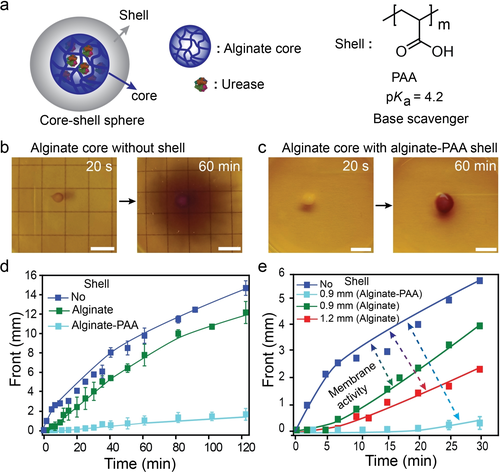
Membrane activity by addition of pH-responsive shells onto urease-loaded gel spheres. a) Core-shell spheres: The core is an alginate sphere with 9 g L−1 urease, the shell is enzyme free and composed of pure alginate or alginate/PAA. b),c) pH front generated from urease-loaded core (b) without shell and (c) with alginate-PAA shell. d) pH front propagation kinetics for different core–shell spheres highlighting the membrane activity with various shell composition. A shell-free sphere is shown for comparison. e) The membrane activity depends on the shell thickness. For the membrane activity experiments: 8 μL of sodium alginate (4.5 wt %) and respective urease (9 g L−1) mixture is used to prepare the core sphere (R=1.1±0.1 mm). Shell wall (thickness=0.9±0.1 mm) is prepared either from 20 μL of sodium alginate (4.5 wt %) or alginate/PAA (3.5 wt %/1 wt %). Fuel solutions: 300 mM urea, 10 mM Na3C/CA (pH 3.5), and 0.2 g L−1 BCP. Scale bars: 5 mm.
Indeed, the bare core sphere with 9 g L−1 urease produces a stable basic pH front immediately upon exposure to the urea-containing fuel solution. However, upon addition of the shells, different membrane activities occur (Figures 4 b–d). Addition of PAA results in the strongest membrane activity. For instance, at 60 min reaction time, the internal sphere has converted to a high pH state, but the diffusive front is very thin and only extends to ca. 10 % of the sphere without the membrane layer (Figures 4 b,c). This is caused by scavenging of the OH− and by the polymeric nature of the PAA counterion for the NH4+, that needs to co-diffuse with OH− for electroneutrality reasons. Meanwhile, the dummy alginate shells present a lower membrane effect with a thickness-dependent decrease of the pH front diffusion at a specific time (Figure 4 e). This is caused by addition of the additional concentric, volumetric diffusion obstacle for the urea (shell thickness). In fact, a careful analysis reveals that all shells, even a dummy alginate shell, slightly expand when placed into the fuel solution (Figure S10). This is due to the increase in pH which swells the shell (and the sphere itself) due to deprotonation of carboxylic acids producing a repulsive force. Hence, this effect also contributes to the more efficient PAA membrane mechanism.
Moreover, we targeted long-range inter-sphere communication. This involves immobilizing the two antagonistic enzymes into separate spheres. This complements above investigations combining both enzymes into one sphere (Figure 3). To this end, urease and esterase were separately immobilized into alginate spheres (R=1.1±0.1 mm), and then esterase spheres were placed a few mm (4–7 mm) away from a central urease sphere into a fuel-containing solution at a start pH of 3.5. We focus on two systems using high-activity (9 g L−1) and low-activity (2.4 g L−1) urease spheres in presence of esterase spheres with similar esterase loading (10–11 g L−1). At low pH (3.5), the esterase gel spheres are almost inactive, while the initial positive feedback of the urea-urease network turns the urease sphere active immediately, resulting in a basic pH front emanating from the urease sphere. After a certain period, when the basic front reaches near the dormant esterase sphere, the local pH is increased, and the esterase sphere is activated to produce a counter acid pH front (Figure 5 a). The images in Figure 5 clearly show the inter-sphere communication for the two experiments having (i) a high-activity urease sphere (9 g L−1) surrounded by 4 high-activity esterase spheres (11 g L−1; Figure 5 b) and (ii) a low-activity urease sphere (2.4 g L−1) surrounded by 3 high-activity esterase spheres (10 g L−1; Figure 5 c). A reference experiment with surrounding esterase-free dummy spheres is shown for comparison (Figure 5 d).
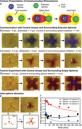
Inter-sphere communication, temporal pH front patterns and inter-sphere attraction. a) General scheme. b)–d) Sphere patterns as described in the Figure. The respective counter acid fronts from esterase sphere in (b) are indicated by red arrows. All urease, esterase, and empty spheres are indicated by blue, green, and gray arrows, respectively. Fuel solution: 100 mM urea, 10 mM Na3C/CA (pH 3.5), and (b) 3.0 M EA, 0.08 g L−1 of BCP; c–d) 1.0 M EA, 0.2 g L−1 of BCP. e) Inter-sphere attraction of experiment shown in (c) top. The black arrows indicate the movement of the surrounding sphere (bottom). f) Plot of center-to-center distance vs. time revealing inter-sphere attraction. Please note that the final center-to-center distance is not 2.2 mm, as expected for 1.1 mm sphere, but slightly larger due to volume expansion when the basic environment is created. Scale bars: 5 mm.
In terms of communication and influence on the pH front, the following regimes can be delineated. The dummy spheres (reference experiment) only produce a diffusion obstacle against the propagation of the stable basic pH front emanating from the central urease sphere (Figure 5 d). However, the surrounding esterase spheres add additional signal-activated negative feedback barriers against the propagation of the basic pH front by producing a counter acid front around themselves. In case of the high-activity urease sphere, the basic pH front can only be annihilated in a very thin layer surrounding the esterase spheres (Figure 5 b). Overall, the basic pH front is able to progress beyond the esterase sphere circle. In case of a low activity urease sphere (Figure 5 c), the pH front is ultimately scavenged by the esterase spheres. This even occurs for a lower number of spheres (3 instead of 4). Strikingly, depending on the distance of the central to the surrounding sphere, the esterase spheres are attracted towards the central urease sphere at 4 mm distance via a diffusiophoretic chemotaxis mechanism to diminish a non-equilibrium concentration gradient60 (Figure 5 e). The center-to-center distance between the central to surrounding sphere is significantly reduced with time (Figure 5 f). The control with the dummy spheres (Figure 5 d), does not show a similar attraction despite having the same distance between the central sphere to the surrounding sphere. This demonstrates the importance of both enzymatic spheres to work in concert, and to provide diffusiophoretic driving force from both sides. Interestingly, this attraction also provides a physical obstruction for urea diffusion and leads to a chemo-structural negative feedback on the activity of the central urease sphere. All the experiments satisfactorily demonstrated the inter-sphere communication.
Building on these pattern formation processes, we hypothesized that they could be leveraged for possible applications for the mild and shear-free growth of soft hydrogel materials61 to construct various shapes without 3D printing tools and other molds. First, we discuss hydrogel growth guided by a basic pH front. For that, we prepared a gelator-fuel solution with urea (300 mM), BCP (0.05 g L−1) and the small gelator molecule Fmoc-ethylenediamine hydrochloride (Fmoc-Et-NH2, 4 g L−1). Fmoc-Et-NH2 is known to lead to gels by nanofiber formation above pH 8.5 (Figure 6 a).62
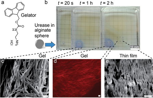
Autonomous growth of hydrogel materials. a) Chemical structure of gelator, Fmoc-Et-NH2. b) Growth of self-assembled gel front by urease-loaded sphere (R=1.05 mm, 9 g L−1 urease). c)–e) The respective (c,e) SEM (scanning electron microscopy) and (d) CLSM (confocal laser scanning microscopy) images at the bottom refer the alignment of nanofibers by the urease-loaded alginate sphere. Gelator-fuel solution contains: 4 g L−1 Fmoc-Et-NH2, 300 mM urea, 10 mM Na3C/CA (pH 3.5), 0.02 g L−1 BCP. Scale bars: 1 μm.
Significant differences occur when adding a urease droplet or a comparable urease sphere to a Fmoc-Et-NH2 solution. Simple addition of a urease droplet (10 μL, 9 g L−1 urease) generates a basic pH volume rapidly, but no defined gel layer and rather disordered nanofibers are observed (Figure S11). This is because the urease diffuses away from the spot of injection (plus unavoidable convection due to pipetting). In contrast, when placing a urease-loaded gel sphere (R=1.1 mm; 9 g L−1 urease) in the Fmoc-Et-NH2-fuel solution, a self-assembled gel front of Fmoc-Et-NH2 nanofibers emanates from the urease sphere after a few minutes, as guided by the basic pH front (Figure 6 b). The growth from the sphere allows some alignment of a nanofibrous morphology as seen by Scanning Electron Microscopy (SEM) and Confocal Laser Scanning Microscopy (CLSM) (Figures 6 c–e). Moreover, a self-assembled thin film is observed in front of the hydrogel regime, which contains similarly aligned short nanofibers but thinner in diameter.
To understand the growth more quantitatively, we 1) encapsulated different urease concentrations into similarly sized spheres, and 2) used differently sized spheres at similar urease concentration (Figures 7 a, b). The growth kinetics of the gel front is accelerated for higher urease concentrations in spheres of the same size (Figure 7 a). For instance, for spheres of similar size, the gel front at high urease loading (9 g L−1) is 12 times further developed compared to low urease loading (≤3 g L−1) after 60 min. The system is also dependent on the size of the spheres, and the thicknesses of the growing hydrogel layers scale with the size of the spheres (Figure 7 b). For example, in case of larger spheres (R≥0.93 mm; urease 9 g L−1), the developed gel layer extends more than 1.5 times further than that of small spheres (R≤0.61 mm; urease 9 g L−1) after 30 min of growth. This signifies that more surface area and higher local enzyme concentration facilitate the self-assembly and growth of the gel front.
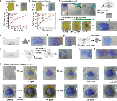
Autonomous growth of various geometrical hydrogel structures. a),b) Visualization and kinetics of gel fronts generated by urease spheres with (a) varied urease concentration at const. R=1.05 mm or (b) varied sphere dimension at const. urease 9 g L−1. c) Fmoc-Et-NH2 gels are non-injectable and cannot be 3D printed. d)–k) Various shapes and scripts including (d) cylinder, (e) triangle, (f) rectangle, (g) number eight, (h) hemisphere, (i) flower, (j,k) “Hi You” are grown from the non-injectable hydrogel without the help of 3D printing or molds. Black arrows indicate the growth of the gel fronts while red arrows in (i) indicate the removal of surrounding dummy spheres. l) More complex 3D pyramid can be constructed by layer-by-layer deposition of gel material by the pre-patterns of urease-loaded gel spheres. Gelator-fuel solution: 4 g L−1 of Fmoc-Et-NH2, 300 mM urea, 10 mM Na3C/CA (pH 3.5), 0.05 g L−1 BCP. Scale bars: 5 mm.
Before addressing the use of such urease spheres and their patterns for growing hydrogel structures, it is important to clarify one key advantage. In fact, growing such Fmoc-Et-NH2 gels allows to overcome one of their 3D printing processing problems, which is their non-injectability. Non-injectability is common to many strongly assembling nanofiber gelators that lead to brittle gels, which fracture under shear. To visualize the problem related to gel extrusion, we prepared a homogeneous gel by mixing urease (0.1 g L−1) and a gelator-fuel solution and attempted to extrude it through a syringe needle to mimic a bioprinting extrusion process (Figure 7 c, Figure S12). Indeed, even gentle operation does not allow proper extrusion, and the gel fractures into a dispersion.
As a remedy to this problem, we show that various geometric hydrogel shapes can be grown autonomously from the non-injectable hydrogel using the basic pH front of the templating urease spheres. To this end, we constructed first various 2D and 2.5D geometric shapes including cylinder, triangle, rectangle, number eight, hemi-sphere, and flowers by utilizing the pH front approach (Figures 7 d–i; Figure S13). Some hydrogel patterns expressing words can also be constructed (Figures 7 j,k). To develop triangles, rectangles, and other gel patterns, first one needs to construct the respective pre-patterns with urease-loaded gel spheres, followed by immersion into the gelator-fuel solution. Guided by the basic pH front, the gel front is developed around the urease sphere patterns which laterally interconnect to produce the desired structures (Figures 7 e–g; Figure S13). Figure 7 d describes the temporal growth of a gel cylinder in more detail.
Among these structures, the construction of the hemisphere and the flower is somewhat special. To construct the hemisphere, the urease sphere is made to float in a gelator-fuel solution by generating an air bubble inside of it. Subsequent hydrogel growth from the interfacially pinned urease-sphere then yields the hemisphere (Figure 7 h; Figure S13). For flowers, first a pre-pattern is constructed in which a urease-loaded sphere is centrally located and surrounded by enzyme-free dummy gel spheres (see section 2 in Supporting Information). The growth of the gel front yields a gel circle after 30 min. Thereafter, removal of the surrounding dummy polymer gel spheres furnishes the flower geometry (Figure 7 i; Figure S13). Building upon such 2D and 2.5D strategies, such pH fronts generated by compartmentalized reaction diffusion systems can also be used to construct more complex 3D structure. For instance, a more complex 3D pyramid can be constructed with a sequential layer-by-layer approach (Figure 7 l).
Overall, this developed pH front/gel growth approach is a potential method to construct gel objects with various shapes in the length scale up to several centimeters with millimeter scale resolution. For example, the 3D pyramid was constructed with the base length and height of 1.8 cm and 1 cm, respectively. We believe that further tunability of sizes and resolution is possible by modifying the starting gel spheres and further fine tuning the gelator/fuel solutions. Earlier works54, 55, 61 utilized reaction diffusion chemistry to trigger hydrogels, but the current approach provides a clear avenue for how to grow complex structures of non-injectable hydrogels.
Conclusion
We demonstrated detailed insights into the cross-regulation behavior, chemical, chemo-mechanical and chemo-structural feedback mechanisms for pH-modulating antagonistic reaction networks compartmentalized into gel spheres and their patterns. This compartmentalization and absence of stirring adds an important reaction/diffusion component to the studied systems, compared to earlier work operating in homogeneous stirred solutions in the context of pH-feedback mechanisms. We started with a detailed understanding of the kinetics, positive and negative feedback loops of simple compartmentalized urea-urease CRNs, or more complex urea-urease/ester-esterase CRNs, for producing active reaction/diffusion pH fronts. The systems feature damping mechanisms, sustained signals or suppressed signals. Moreover, we demonstrated how additional responsive and non-responsive layers in core–shell spheres can further control the emanating pH fronts. Complementing the systems of antagonistic enzymes confined into single spheres, we constructed systems of spheres, in which the antagonistic enzymes were compartmentalized into different spheres that were arranged in patterns. These concepts allowed to identify inter-sphere regulatory effects, such as diffusion obstacles for the substrate and the pH-front, local annihilation of the pH-front growing from the central sphere only in close proximity of the surrounding antagonistic spheres, or global annihilation of the pH-front by the surrounding antagonistic spheres using overpowering signal-countersignal processes. Strikingly, the inter-sphere communication via catalytically induced signals triggered a diffusiophoretic attraction of the spheres, and ultimately a chemo-structural feedback with a spatial pattern reconfiguration. Building upon such controlled pH fronts and pH front patterns, we showed that pH fronts can be used to grow hydrogel material with some in situ alignment of nanostructures. As such it adds a valuable tool for achieving structures inaccessible by 3D printing, by spatially pre-organizing reactive spheres.
In a more generalized way, we believe that this study will be helpful in understanding and designing other compartmentalized synthetic feedback-controlled and compartmentalized reaction networks in the emerging domain of systems chemistry. It also paves the way and gives important examples to transition feedback-controlled reaction networks from the systems chemistry domain into material systems design to target different functionalities. For instance, it can open a scope for 3D shaping of non-injectable supramolecular gels useful for applications in near future.
Acknowledgements
We acknowledge support by the DFG in WA3084/4-2. I.M. acknowledges partial support by a Marie Curie FRIAS COFUND fellowship and the funding from European Union's Horizon 2020 research and innovation program under the Marie Skłodowska-Curie grant agreement No 754340. We acknowledge Dr. Avik Samanta for his valuable suggestions. Open access funding enabled and organized by Projekt DEAL.
Conflict of interest
The authors declare no conflict of interest.


