An Efficient FPGA Implementation of Optimized Anisotropic Diffusion Filtering of Images
Abstract
Digital image processing is an exciting area of research with a variety of applications including medical, surveillance security systems, defence, and space applications. Noise removal as a preprocessing step helps to improve the performance of the signal processing algorithms, thereby enhancing image quality. Anisotropic diffusion filtering proposed by Perona and Malik can be used as an edge-preserving smoother, removing high-frequency components of images without blurring their edges. In this paper, we present the FPGA implementation of an edge-preserving anisotropic diffusion filter for digital images. The designed architecture completely replaced the convolution operation and implemented the same using simple arithmetic subtraction of the neighboring intensities within a kernel, preceded by multiple operations in parallel within the kernel. To improve the image reconstruction quality, the diffusion coefficient parameter, responsible for controlling the filtering process, has been properly analyzed. Its signal behavior has been studied by subsequently scaling and differentiating the signal. The hardware implementation of the proposed design shows better performance in terms of reconstruction quality and accelerated performance with respect to its software implementation. It also reduces computation, power consumption, and resource utilization with respect to other related works.
1. Introduction
Image denoising is often employed as a preprocessing step in various applications like medical imaging, microscopy, and remote sensing. It helps to reduce speckles in the image and preserves edge information leading to higher image quality for further information processing [1]. Normal smoothing operations using low-pass filtering do not take into account intensity variations within an image and hence blurring occurs. Anisotropic diffusion filter performs edge-preserving smoothing and is a popular technique for image denoising [2]. Anisotropic diffusion filtering follows an iterative process and it requires a fairly large amount of computations to compute each successive denoised image version after every iteration. This process is continued until a sufficient degree of smoothing is obtained. However, a proper selection of parameters as well as complexity reduction of the algorithm can make it simple. Various edge-preserving denoising filters do exist targeting various applications according to the cost, power, and performance requirements. However, as a case study, we have undertaken to optimize the anisotropic diffusion algorithm and design an efficient hardware equivalent to the diffusion filter that can be applied to embedded imaging systems.
Traditional digital signal processors are microprocessors designed to perform a special purpose. They are well suited to algorithmic-intensive tasks but are limited in performance by clock rate and the sequential nature of their internal design, limiting their maximum number of operations per unit time. A solution to this increasing complexity of DSP (Digital Signal Processing) implementations (e.g., digital filter design for multimedia applications) came with the introduction of FPGA technology. This serves as a means to combine and concentrate discrete memory and logic, enabling higher integration, higher performance, and increased flexibility with their massively parallel structures. FPGA contains a uniform array of configurable logic blocks (CLBs) [3–5], memory, and DSP slices, along with other elements [6]. Most machine vision algorithms are dominated by low and intermediate level image processing operations, many of which are inherently parallel. This makes them amenable to parallel hardware implementation on an FPGA [7], which have the potential to significantly accelerate the image processing component of a machine vision system.
2. Related Works
A lot of research can be found on the requirements and challenges of designing digital image processing algorithms using reconfigurable hardware [3, 8]. In [1], the authors have designed an optimized architecture capable of processing real-time ultrasound images for speckle reduction using anisotropic diffusion. The architecture has been optimized in both software and hardware. A prototype of the speckle reducing anisotropic diffusion (SRAD) algorithm on a Virtex-4 FPGA has been designed and tested. It achieves real-time processing of 128 × 128 video sequences at 30 fps as well as 320 × 240 pixels with a video rate speed of 30 fps [8, 9]. Atabany and Degenaar [10] described the architecture of splitting the data stream into multiple processing pipelines. It reduced the power consumption in contrast to the traditional spatial (pipeline) parallel processing technique. But their system partitioning architecture clearly reveals nonoptimized architecture as the N × N kernel has been repeated over each partition (complexity of which is O(N2)). Moreover, their power value is completely estimated. The power measurements of very recent hardware designed filters, namely, the bilateral and the trilateral filter [11–13], have also been undertaken. In [14], the authors have introduced a novel FPGA-based implementation of 3D anisotropic diffusion filtering capable of processing intraoperative 3D images in real time making them suitable for applications like image-guided interventions. However, it did not reveal the acceleration rate achieved in hardware with respect to the software counterpart (anisotropic diffusion) and energy efficiency information as well as any filtered output image analysis. Authors in [15] have utilized the ability of Very Long Instruction Word (VLIW) processor to perform multiple operations in parallel using a low cost Texas Instruments (TI) digital signal processor (DSP) of series TMS320C64x+. However, they have used the traditional approach of 3 × 3 filter masks for the convolution operation used to calculate the filter gradients within the window. It increased the computation of arithmetic operations. There is also no information regarding the power consumption and energy efficiency.
We have also compared our design with the GPU implementations of anisotropic diffusion filters for 3D biomedical datasets [16]. In [16], the authors have implemented biomedical image datasets in NVIDIA’s CUDA programming language to take advantage of the high computational throughput of GPU accelerators. Their results show an execution time of 0.206 sec for a 1283 dataset for 9 iterations, that is, for a total number of (1283∗9) pixels where 9 is the number of iterations to receive a denoised image. However, once we consider 3D image information, the number of pixels increases thrice. In this scenario, we need only 0.1 seconds of execution time in FPGA platform as an approximation ratio with a much reduced MSE (Mean Square Error) of 53.67 instead of their average of 174. The acceleration rate becomes 91x with respect to CPU implementation platform unlike the case in GPU with 13x. Secondly, their timing (execution) data does not include the constant cost of data transfer (cost of transferring data between main memory on the host system and the GPU’s memory which is around 0.1 seconds). It measures only the runtime of the actual CUDA kernel which is an inherent drawback of GPU. This is due to the architecture which separates the memory space of the GPU from that of its controlling processor. Actually, GPU implementation takes more time to execute the same [17] due to lot of memory overhead and thread synchronization. Besides GPU implementation or customized implementations on DSP kits of Texas Instruments have got their own separate purpose of implementation.
3. Our Approach
- (i)
Firstly, the independent sections of the algorithm that can be executed in parallel have been identified followed by a detailed analysis of algorithm optimization. Thereafter, a complete pipeline hardware design of the parallel sections of the algorithm has been accomplished (gradient computations, diffusion coefficients, and CORDIC divisions).
- (ii)
Our proposed hardware design architecture completely substituted standard convolution operation [18], required for the evaluation of the intensity gradients within the mask. We used simple arithmetic subtraction to calculate the intensity gradients of the neighboring pixels within a window kernel, by computing only one arithmetic (pixel intensity subtraction) operation. The proposed operation saved 9 multiplications and 8 addition operations per convolution, respectively (in a 3 × 3 window).
- (iii)
The number of iterations, which is required during the filtering process, has been made completely adaptive.
- (iv)
Besides increasing the accuracy and reducing the power reduction, a huge amount of computational time has been reduced and the system has achieved constant computational complexity, that is, O(1).
- (v)
We performed some performance analysis on the diffusion coefficient responsible for controlling the filtering process, by subsequently differentiating and scaling, which resulted in enhanced denoising and better quality of reconstruction.
- (vi)
Due to its low power consumption and resource utilization with respect to other implementations, the proposed system can be considered to be used in low power, battery operated portable medical devices.
The detailed description of the algorithm optimization and the hardware parallelism as well as the achieved acceleration are described in Section 5. As discussed above, in order to implement each equation, one convolution operation needs to be computed with a specified mask as per the directional gradient. Further optimization has been achieved by parallel execution of multiple operations, namely, the intensity gradient (∇I) and the diffusion coefficients (Cn) within the filter kernel architecture, being discussed in hardware design sections. To the best of our knowledge, this is one of the first efficient implementations of the anisotropic diffusion filtering, with respect to throughput, energy efficiency, and image quality realized in hardware.
The paper is organized as follows. Section 4 describes the algorithm background, Section 5 briefly explains the materials and methods of the approach in multiple subsections, Section 6 discusses the results, and Section 7 ends up with the conclusions and future projections.
4. Algorithm (Background Work)
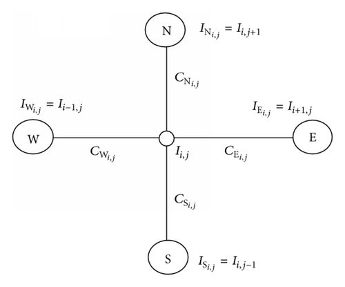
Equation (1) above can be discretized on a square lattice with vertices representing the brightness, and arcs representing the conduction coefficients, as shown in Figure 1.
5. Design Method and Hardware Details
5.1. Replacing the Convolution Architecture (Proposed by Us)
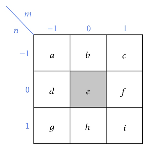
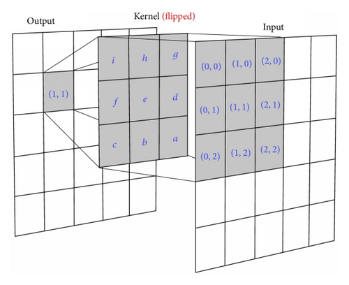
This operation is continued for all other directions. This shows that the convolution operation can be simplified down to a single arithmetic subtraction, thereby drastically reducing the number of operations, the complexity, and the hardware resources. It also enhances the speed, as discussed in the latter sections of the paper.
The gradient estimation of the algorithm for various directions is shown in equationarray (2), which was originally realized in software [19] by means of convolution of 3 × 3 gradient kernel sliding over the image. It consisted of 9 multiplications and 8 additions for a single convolution operation (so total of 17 operations). Therefore, our hardware realization of the convolution kernel operation (computing gradient (2)) has been substituted by a single arithmetic subtraction operation, reducing a huge amount of computation. The detailed hardware implementation is described in Section 5.5.
5.2. Adaptive Iteration (Proposed by Us)
The iteration step of the filter shown in (3) needs to be manually set in the classical version of the algorithm, which was its main drawback. However, that has been made adaptive by the proposed Algorithm 1. The number of iterations completely depend upon nature of the image under consideration.
-
Algorithm 1: Adaptive iteration algorithm.
-
Input: Denoised images Ii,j at every iteration step of (3).
-
Comments: Referring (3).
-
(1) The differences between denoised output images at every iteration step is found out.
-
-
(2) The difference between the maximum and minimum of the difference matrix found out in
-
Step (1) is computed at every iteration step.
-
-
(3) Steps (1) and (2) are continued until the condition shown below is met.
-
-
(4) Once the condition in Step (3) is met the execution is stopped which in turn stops the
-
number of iteration thereby making it adaptive.
-
(5) Display the number of iteration thus encountered and exit.
5.3. In-Depth Analysis of the Diffusion Coefficient (Proposed by Us)
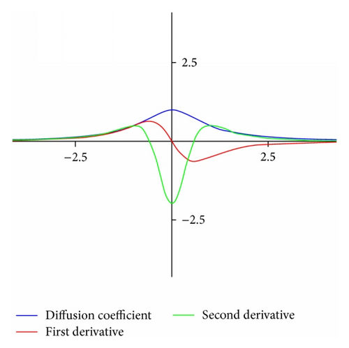
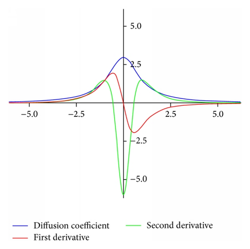
Upon solving (17), the roots appear as . However, keeping the roots coordinate the same, the magnitude increases upon scaling as is clear from graphs (see Figure 3(b)).
So we can conclude here that the smoothing effect can be performed in a controlled manner by properly scaling the derivative of the coefficient. As a result, images with high-frequency spectrum are handled in a different way unlike their counterpart.
Since the coefficient controls the smoothing effect while denoising, it also effects the number of iterations incurred to achieve the magnitude threshold κ in (4) for smoothing. This signal behavior of the diffusion coefficient should be very carefully handled. Proper selection of its magnitude depends upon the image selected for denoising.
5.4. Algorithm of Hardware Design Flow
The first step requires a detailed algorithmic understanding and its corresponding software implementation. Secondly, the design should be optimized after some numerical analysis (e.g., using algebraic transforms) to reduce its complexity. This is followed by the hardware design (using efficient storage schemes and adjusting fixed-point computation specifications) and its efficient and robust implementation. Finally, the overall evaluation in terms of speed, resource utilization, and image fidelity decides whether additional adjustments in the design decisions are needed (ref. Figure 4). The algorithm background has been described in the previous Section 4.
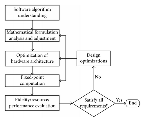
The workflow graph shown in Figure 5 shows the basic steps of our design implementation in hardware.

5.5. Proposed Hardware Design Implementation
The noisy image is taken as an input to the FPGA through the Gateway_In (see Figure 5) which defines the FPGA boundary and converts the pixel values from floating to fixed-point types for the hardware to execute. The anisotropic diffusion filtering is carried out after this. The processed pixels are then moved out through the Gateway_Out again converting the System Generator fixed-point or floating-point data type.
Figure 5 describes the abstract view of the implementation process. The core filter design has been elaborated in descriptive components in a workflow modular structure shown in Figure 6. The hardware design of the corresponding algorithm is described in Figures 7–14.
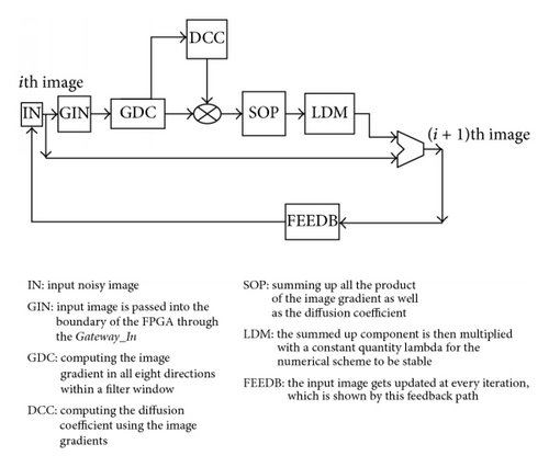
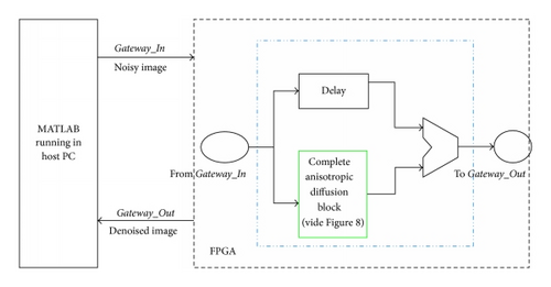

Explanation of Hardware Modules as per the Workflow Diagram. Figure 7 shows the magnified view of the blue boundary block implementing equation (3) of Figure 5 (i.e., the anisotropic diffusion filtering block). Figure 7 shows the hardware design which gets fired t times due to t number of iterations from the script when executed.
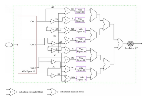
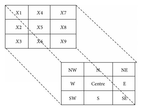
Equation (3) has been described in words in detail in Figure 6 with iteration required to meet the necessary condition for the classical anisotropic diffusion equation. Equation (3) shows that gets updated at every iteration and has been realized with the hardware design in Figure 8. The green outlined box in Figure 7 has been detailed in Figure 8. The line buffer reference block buffers a sequential stream of pixels to construct 3 lines of output. Each line is delayed by 150 samples, where 150 is the length of the line. Line 1 is delayed by (2∗150 = 300) samples, each of the following lines are delayed by 150 fewer samples, and line 3 is a copy of the input. It is to be noted that the image under consideration used here is of resolution 150 × 150, and in order to properly align and buffer the streaming pixels, the line buffer should be of the same size as the image. As shown in Figure 9, X1 to X9 imply a chunk of 9 pixels and their corresponding positions with respect to the middle pixel X5 as north (N), south (S), east (E), west (W), north-east (NE), north-west (NW), and so forth, as shown with a one-to-one mapping in the lower second square box.
This hardware realization of the gradient computation is achieved by a single arithmetic subtraction as described in Section 5.1.
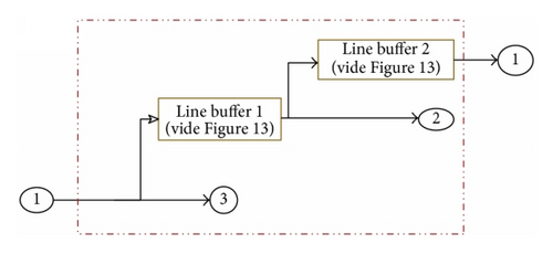
Now, referring to this window, the difference in pixel intensities from the center position of the window to its neighbors gives its gradient as explained in equationarray (2). This difference in pixel intensities is calculated in the middle of the hardware section as shown in Figure 8. Here, X1 denotes the central pixel of the processing window and the corresponding differences with pixel intensities in position X1, X2, X3, …, X9 denote the directional gradient (X1 − X5 = grad_northwest, X2 − X5 = grad_west, …, X9 − X5 = grad_southeast). The pixels are passed through the line buffers (discussed in Section 5.6) needed for proper alignment of the pixels before computation. This underlying architecture is basically a memory buffer needed to store two image lines (see Section 5.6) implemented in the FPGA as a RAM block. The deep brown outlined block in Figure 8 (from where the three out lines are coming out) contains the detailed diagram and working principle of the buffering scheme in Figure 12.
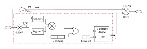
Now, let us discuss the bottom-up design approach to make things more transparent. Referring to (3), the coefficient Cn is defined in equationarray (6) which has been realized in hardware as shown in Figure 11 where ‖E‖ is the intensity gradient calculating variable and κ is the constant value 15. So 1/κ = 1/15 = 0.0667 which gets multiplied with the input gradient ‖E‖ squared up and then added with a unitary value and the resultant becomes the divisor with 1 the dividend. Referring to the hardware design in Figure 11, the CORDIC divisor has been used to compute the division operation in (4) and the rest is quite clear. Now, Figure 10 is the hardware design of the equations CnEn and 1/2CnEn as per the individual components of (3). For the gradient north, south, east, and west, it is needed to multiply only 1/2 with CnEn and 1 for others. We have seen the coefficient computation of equationarray (6) where the input is the gradient En = ∇In. This is the same input in the hardware module in Figure 10 needed to compute coefficient Cn. The output of Figure 10 is nothing but the coefficient multiplied with the gradient En as shown.
The delays are injected at the intervals to properly balance (synchronize) the net propagation delays. Finally, all the output individual components of the design shown in Figure 8 are summed up and the lambda (λ) is finally multiplied with the added results. This implementation of the line buffer is described in the next subsection.
Each component in (3), that is, C · ∇I, requires an initial 41-unit delay for each processed pixel to produce (CORDIC: 31-unit delay, multiplier: 3-unit delay, and register: 1-unit delay). The delay balancing is done as per the circuitry. However, this delay is encountered at first and from the next clock pulse each pixel gets executed per clock pulse since the CORDIC architecture is completely pipelined.
5.6. Efficient Storage/Buffering Schemes
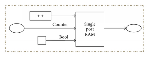
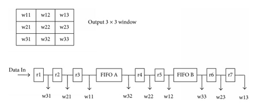
Figure 12 describes the efficiency in the storage/buffering scheme. Figures 12 and 13 describe a window generator to buffer reused image intensities diminishing data redundancies. This implementation of the line buffer uses a single port RAM block with the read before write option as shown in Figure 13. Two buffer lines are used to generate eight neighborhood pixels. The length of the buffer line depends on the number of pixels in a row of an image. A FIFO structure is used to implement a 3 × 3 window kernel used for filtering to maximize the pipeline implementation. Leaving the first 9 clock cycles, each pixel is processed per clock cycle starting from the 10th clock cycle. The processing hardware elements never remain idle due to the buffering scheme implemented with FIFO (Figure 14). Basically, this FIFO architecture is used to implement the buffer lines.
With reference to Figure 14, it is necessary that the output of the window architecture should be vectors for pixels in the window, together with an enable which is used to inform an algorithm using the window generation unit as to when the data is ready to process. To achieve maximum performance in a relatively small space, FIFO architectural units specific to the target FPGA were used.
6. Results and Discussion
In this paper, we presented an efficient architecture of the FPGA prototyped hardware design of an optimized anisotropic diffusion filtering on image. The algorithm has been successfully implemented using FPGA hardware using the System Generator platform with Intel(R) Core(TM) 2 Duo CPU T6600 @ 3.2 GHz platform and Xilinx Virtex-5 LX110T OpenSPARC Evaluation Platform (100 MHz) as well as Avnet Spartan-6 FPGA IVK.
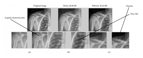
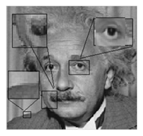
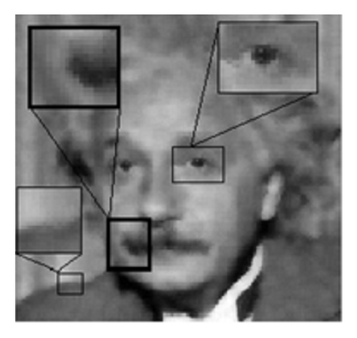
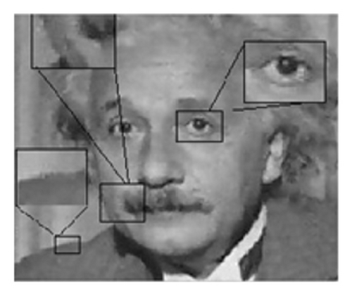
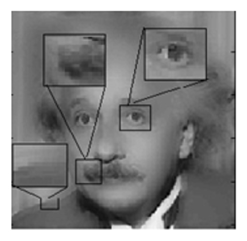
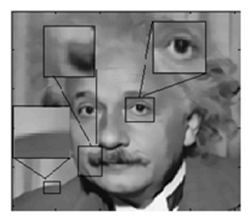
Here, the hardware filter design is made using the Xilinx DSP blockset. The algorithm [2] has been analyzed and optimally implemented in hardware with a complete parallel architecture. The proposed system leads to improved acceleration and performance of the design. The throughput is increased by 12 to 33% in terms of frame rate, with respect to the existing state-of-the-art works like [20–22]. Figures 15, 16, and 17 show the denoising performances. Figure 15 shows a denoised image of various human skeletal regions which was affected by noise. Figure 16 shows the quality comparison between the hardware and its corresponding software implementations. Figure 17 shows the various denoising filter performances. Fine texture regions have been magnified to show the achieved differences and improvement.

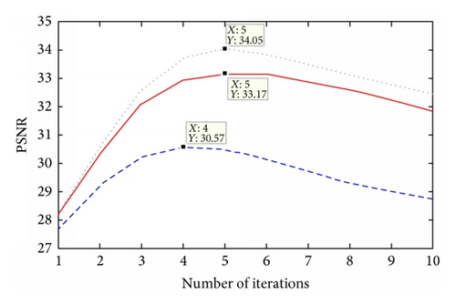
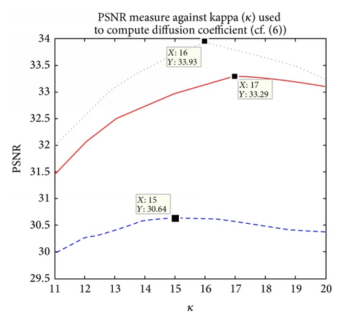
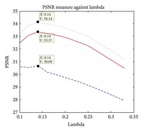
Figures 18 and 19 denote the accuracy measures.
With regard to data transfer requirement, there is a huge demand for fast data exchange between the image sensor and the computing platform. For example, transferring a 1024 × 1024 grayscale video sequence in real time requires a minimum data transfer rate of 1024 × 1024 pixels/frame∗1 byte/pixel∗30 fps = 30 Mbps. In order to achieve this data rate, a high performance I/O interface, such as a PCI or USB, is necessary. We have used USB 2.0 (Hi-Speed USB mode) supporting 60 Mbps data rate.
For a 512 × 512 image resolution, time taken to execute in software is 0.402 seconds and 0.101 seconds for 150 × 150 size grayscale image approximately (cf. Table 1).
Image resolution |
Software execution time (seconds) |
Hardware execution time (seconds) |
Accelerate rate |
|---|---|---|---|
| 150 × 150 | 0.101 | 0.0011 | (0.101/0.0011) = 91 |
| 512 × 512 | 0.402 | 0.0131 | (0.402/0.0131) = 30 |
| Method | Std. dev. = 12 | Std. dev. = 15 | Std. dev. = 20 | |||
|---|---|---|---|---|---|---|
| SSIM | PSNR (dB) | SSIM | PSNR (dB) | SSIM | PSNR (dB) | |
| (a) ADF [2] | 0.9128 | 29 | 0.8729 | 27.82 | 0.8551 | 24.93 |
| (b) NLM [27] | 0.9346 | 28.2 | 0.9067 | 27.29 | 0.8732 | 25.64 |
| (c) BF [12] | 0.9277 | 27 | 0.8983 | 28.54 | 0.8809 | 24.28 |
| (d) TF [13] | 0.8139 | 25.22 | 0.7289 | 22.87 | 0.6990 | 21.98 |
|
0.9424 | 30.01 | 0.9245 | 28.87 | 0.8621 | 25.86 |
Simulation activity files (SAIF) from simulation is used for accurate power analysis of a complete placed and routed design.
As already explained, the buffer line length needs to be equal to that of the image resolution. Now, as the resolution increases, the buffering time increases too. Now, it is obvious that increasing image resolution, the number of pixels to be processed in both hardware and software increases. This difference is proportionate. But what makes the difference in acceleration rate as a result of change in resolution (see Table 1) is created by the buffering scheme of the hardware. In software, the image can be read at one go unlike in hardware where the pixels need to be serialized while reading (see Figures 12 and 14).
Case 1. The image resolution used for this experiment is 150 × 150, so a total of 22500 pixels. Therefore, a sum total of (22500∗5) = 112500 pixels have been processed for five iterations of the algorithm. Our proposed hardware architecture is such that it can process per pixel per clock pulse (duration 10 ns). The clock frequency of the FPGA platform on which the experiment has been performed is 100 MHz (period = 10 ns). The Gateway_In of the FPGA boundary has an unit sample period. Therefore, the total time taken to process is 22500 pixels∗5 iterations∗10 ns = 0.0011 seconds in hardware (also has been cross-checked complying with (19)).
Whereas only in software environment the total time taken to execute in the host PC configuration mentioned above is 0.101 seconds, thus a total acceleration of (0.101/0.0011 = 91x) in execution speed has been achieved in FPGA-in-the-loop [23] experimental setting.
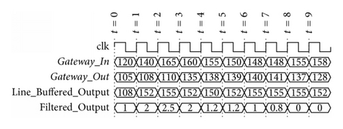
Case 2. Therefore, for image resolution 512 × 512, the total hardware time required to process is 262144 pixels∗5 iterations∗10 ns = 0.0131 seconds (also has been cross-checked complying with (19)). Figure 20 shows that per pixel gets executed per clock cycle starting from the FPGA boundary Gateway_In to Gateway_Out.
The experiment has been implemented 10 times and the corresponding mean squared error (MSE) obtained has been averaged by 10 to get the averaged MSEav, which is used to calculate the PSNR. Since the noise is random, therefore averaging is performed while computing the PSNR.
As seen from the processed images, our result resembles the exact output very closely. The difference is also clear from the difference of the PSNR and SSIM values (Table 2).
A closer look has been plotted with a one-dimensional plot shown in Figure 21, which clearly exposes the smoothing effect at every iterative step.

FPGA-in-the-loop (FIL) verification [23] has been carried out. It includes the flow of data from the outside world to move into the FPGA through its input boundary (a.k.a Gateway_In), get processed with the hardware prototype in the FPGA, and be returned back to the end user across the Gateway_Out of the FPGA boundary [24, 25]. This approach also ensures that the algorithm will behave as expected in the real world.
Figure 22 shows the frames per second achieved for images of various resolutions. The power measurements in our proposed method have been analyzed after the implementation phase (placement and routing) and are found to be more accurate and less than their stronger counterpart, namely, the hardware implementation of the bilateral and trilateral filter as shown in Table 3.
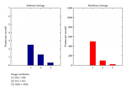
Table 4 denotes the resource utilization for both the hardware platforms for our implementation and a very strong benchmark implementation (its counterpart) of bilateral filter. It shows that a lot of acceleration has been achieved for anisotropic (cf. Table 5) with respect to its counterpart bilateral at the cost of a marginal increase in percentage of resource utilization (cf. Table 5).
| Percentage utilization | Image size (150 × 150) | ||
|---|---|---|---|
Virtex-5 LX110T OpenSPARC FPGA (utilized/total number) (anisotropic diffusion) |
Fully parallel and separable single dimensional architecture (bilateral filter) for the same OpenSPARC device | Avnet Spartan 6 industrial video processing kit (anisotropic diffusion) |
|
| Occupied slices | 5225/17280 | 6342 and 3144 | 3810/23038 |
| (30%) | (37% and 18%) | (16%) | |
| Slice LUTs | 14452/69120 | 11689 and 8535 | 11552/92152 |
| (20%) | (17% and 12%) | (12%) | |
| Block-RAM/FIFO/RAMB8BWERs | 1/148 | 22 and 22 | 2/536 |
| (1%) | (15% and 15%) | (1%) | |
| Flip flops | 17309/69120 | 16167 and 5440 | 15214/69120 |
| (25%) | (23% and 8%) | (22%) | |
| Bonded IOBs | 46/640 | 1 and 1 | 46/396 |
| (7%) | (1% and 1%) | (11%) | |
| Mults/DSP48Es/DSP48A1s | 55/64 | 0 and 0 | 81/180 |
| (85%) | (0% and 0%) | (45%) | |
| BUFGs/BUFCTRLs | 1/32 | 4 and 4 | 1 |
| (3%) | (13% and 13%) | (3%) | |
| Filtering techniques | AD filtering | BF | ||||||
|---|---|---|---|---|---|---|---|---|
| Image resolution | A | B | C | D | A | B | C | D |
| Execution time (software in seconds) | 0.101 | 0.153 | 0.402 | 1.1 | 0.5 | 1.1 | 2.5 | 11.5 |
| Acceleration rate in software for anisotropic over bilateral (approx.) | 3x | 3x | 3x | 3x | — | — | — | — |
| Acceleration rate when executed in hardware with respect to software for BF | — | — | — | — | 70x | 6x | 7x | 3x |
| Acceleration rate when executed in hardware with respect to software for AD | 91x | 46x | 30x | 21x | — | — | — | — |
The complexity analysis has been compared with some of the benchmark works and is shown in Table 6.
| Algorithm | Complexity |
|---|---|
| Constant time polynomial range approach [30] | O(1) |
| Trilateral filter [13] | More than the [12, 27, 30–35] |
| NLM [27] | x2 · y2 · N · M |
| Brut force approach [31] | O(|S|2) |
| Layered approach [32] |
|
| Bilateral grid [33] approach |
|
| Separable filter kernel approach [34] | O(|S|σs) |
| Local histogram approach [35] | O(|S|logσs) |
| Constant time trigonometric range approach [12] | O(1) |
| Classical anisotropic diffusion [2] | Nonlinear |
| Optimized anisotropic diffusion (OAD) (our approach) | O(1) |
6.1. Considerations for Real-Time Implementations
So in order to process one frame, the total number of clock cycles required is given by (M · N/tp + ξ) for a single processing unit. For ncore > 1, one can employ multiple processing units.
Let us evaluate a case study applying (19) for our experiment.
For 512 × 512 resolution image, M = 262144, N = 5, tp = 1, that is, per pixel processed per clock pulse, ξ = 1050, that is, the latency in clock cycle, f = 100 MHz, and ncore = 1. Therefore, tframe = 0.013 seconds = 13 ms ≤ 33 ms (i.e., much less than the minimum timer threshold required to process per frame in real-time video rate). With regard to data transfer requirement, there is a huge demand for fast data exchange between the image sensor and the computing platform. For example, transferring a 1024 × 1024 grayscale video sequence in real time requires a minimum data transfer rate of 1024 × 1024 pixels/frame∗1 byte/pixel∗30 fps = 30 Mbps. In order to achieve this data rate, a high performance I/O interface, such as a PCI or USB, is necessary. Our USB 2.0 (Hi-Speed USB mode) supports 60 Mbps data rate, which is just double the minimum requirement of 30 Mbps which catered our purpose with ease.
- (i)
Accuracy. We have performed our experiments on approximately 65–70 images (both natural and medical) and they are producing successful results. We discovered that every time they yielded the max PSNR for the following selected parameter values shown in Figures 18 and 19.
- (ii)
Power. We can claim our design to be energy efficient as the power consumption for the design has reduced in comparison to other benchmark works for an example image of a given resolution as shown (cf. Table 3 by reducing the number of computations [26], NB also tested for images of various resolutions) with respect to other state-of-the-art works cited previously [11, 12].
- (iii)
Diffusion Coefficient Analysis. We performed some performance analysis on the diffusion coefficient responsible for controlling the filtering process, subsequently by differentiation and scaling. The changes in the signal behavior help to perform a proper selection of the scaling parameter needed for filtering different image types. PSNR and SSIM performance measures reflect the reconstructed denoising quality affected by random noise.
- (iv)
Complexity. Previous implementations [10, 15] used normal convolution operation to calculate the intensity gradients whose computational complexity is of O(N2). Even if the normal convolution is substituted by single dimensional architecture [12], the computational complexity would reduce to O(N). However, we have realized the same with a single arithmetic subtraction operation, making it convenient by arranging the pixels in the favorable order, thereby reducing the complexity to O(1). That is, O(N2) → O(N) → O(1), that is, the least complexity achievable.
- (v)
Speed. Besides having O(1) complexity, our hardware architecture of the algorithm has been formulated in parallel. This allows us to further accelerate its speed, since all the directional gradient computations have been done in parallel, thereby saving the CORDIC (processor) divider delay time by (41∗7∗10) = 2870 ns. Each CORDIC block has 31-unit delay, together with multipliers and registers and thereby saving 7 directions (due to parallel executing) where 10 ns is each clock pulse.
- (vi)
Adaptive Iteration. We have designed Algorithm 1, which shows the steps of intelligent adaptation of the number of iterations.
- (vii)
The filter design has been implemented in one grayscale channel; however, it can be replicated for all other color channels.
- (viii)
Reconstruction Quality. Last but not least, the denoised image quality has been measured against benchmark quality performance metrics.
7. Conclusions
In this paper, we presented an efficient hardware implementation of edge-preserving anisotropic diffusion filter. Considerable gain with respect to accuracy, power, complexity, speed, and reconstruction quality has been obtained as discussed in Section 6. Our design has been compared to the hardware implementation of state-of-the-art works with respect to acceleration, energy consumption, PSNR, SSIM, and so forth. From the point of view of the hardware realization of edge-preserving filters, both bilateral and anisotropic diffusion yield satisfying results, but still the research community prefers bilateral filter as it has less parameters to tune and is noniterative in nature. However, recent implementations of the same are iterative for achieving higher denoised image quality. So it can be concluded that if a proper selection of parameters can be done (has been made adaptive without manual intervention in our case) in case of anisotropic diffusion filtering, then real-time constraints can be overcome without much overhead. We have not performed the hardware implementation of the nonlocal means algorithm as it contains exponential operations at every step. Hardware implementation of the exponential operation introduces a lot of approximation errors.
While GPU implementations of the same do exist, however, we have undertaken this work as a case study to measure the hardware performance of the same.
Additional work on testing with more images, design optimization, and real-time demonstration of the system and a suitable physical design (floorplanning to masking) is to be carried out in future. It is to be noted that we have designed one extended trilateral filter algorithm (edge-preserving/denoising) which is also producing promising results (not been published yet).
Till now, there have been more advanced versions of anisotropic diffusion algorithms even with more optimized/modified versions. But they are all optimized and targeted to specific applications. However, this design forms the base architecture for all the other designs. Any kind of modification of the algorithm and its corresponding hardware design can be done keeping the similar base architecture.
Competing Interests
The authors declare that there are no competing interests regarding the publication of this paper.
Acknowledgments
This work has been supported by the Department of Science and Technology, Government of India, under Grant no. DST/INSPIRE FELLOWSHIP/2012/320 as well as the grant from TEQIP phase 2 (COE) of the University of Calcutta providing fund for this research. The authors also wish to thank Mr. Pabitra Das and Dr. Kunal Narayan Choudhury for their valuable suggestions.


