Biomechanical Effects of Multi-segment Fixation on Lumbar Spine and Sacroiliac Joints: A Finite Element Analysis
Geng Zhao, Lianlei Wang and Hongwei Wang contributed equally to this work.
Disclosure: The authors declare that they have no conflict of interest.
Abstract
Objective
Spine fixation surgery affects the biomechanical environment in the sacroiliac joint (SIJ), which may lead to the SIJ pain or degeneration after surgery. The purpose of this study is to determine the impact of the number and position of fixed segments on the SIJs and provide references for surgeons to plan fixation levels and enhance surgical outcomes.
Methods
The intact lumbar-pelvis finite element (FE) models and 11 fixation FE models with different number and position of fixed segments were developed based on CT images. A 400N follower load and 10° range of motion (ROM) of the spine were applied to the superior endplate of L1 to simulate the flexion, extension, bending and torsion motion after surgery. The peak stress on the SIJs, lumbar intervertebral discs, screws and rods were calculated to evaluate the biomechanical effects of fixation procedures.
Results
With the lowermost instrumented vertebra (LIV) of L5 or S1, the peak stress on SIJs increased with the number of fixed segments increasing. The flexion motion led to the greater von Mises stress on SIJ compared with other load conditions. Compared with the intact model, peak stress on all fixed intervertebral discs was reduced in the models with less than three fixed segments, and it increased in the models with more than three fixed segments. The stress on the SIJ was extremely high in the models with all segments from L1 to L5 fixed, including L1-L5, L1-S1 and L1-S2 fixation models. The stress on the segment adjacent to the fixed segments was significant higher compared to that in the intact model. The peak stress on rods and screws also increased with the number of fixed segments increasing in the flexion, extension and bending motion, and the bending and flexion motions led to the greater von Mises stress on SIJs.
Conclusion
Short-term fixation (≤2 segments) did not increase the stress on the SIJs significantly, while long-term segment fixation (≥4 segments) led to greater stress on the SIJs especially when all the L1-L5 segments were fixed. Unfixed lumbar segments compensated the ROM loss of the fixed segments, and the preservation of lumbar spine mobility would reduce the risks of SIJ degeneration.
Introduction
Approximately 30% of patients with low back pain suffer from sacroiliac joint (SIJ) pain.1-3 The typical symptoms of SIJ pain include unilateral or bilateral low back pain, which might radiate to the buttock, groin, thigh and even foot.4 Patients with SIJ pain have worse quality of life than patients with mild heart failure and respiratory diseases.5
SIJ pain is believed to be related to pathological conditions such as sacroiliitis, rheumatic, infectious and oncologic conditions.6 However, several studies have shown that SIJ pain also occurs after spine fixation surgery, which is one of the causes of failed back surgery syndrome.7, 8 Katz et al.9 reported that the patients suffering from SIJ pain accounted for 32% of patients who experienced low back pain after lumbosacral fixation. Frymoyer et al.10 reported that 37% of patients with persistent low back pain after lumbar fixation to the sacrum were referred to the SIJ. Maigne et al.11 observed that patients who had undergone fixation surgery had a greater risk of SIJ pain than did the healthy population. DePalma et al.12 reported that lumbosacral fusion increased the probability of positive SIJ blocks. Therefore, extra attention needs to be given to the treatment and treatment of SIJ dysfunction after surgery.13
The relationship between adjacent segment degeneration and spinal surgery has been confirmed in previous reports.14, 15 Numerous studies have shown that the stress on the facet joints and intervertebral discs in adjacent segments increases, and the range of motion in adjacent segments also increases after spinal fixation.16-18 The SIJs are the adjacent joints of the surgical segment for lumbosacral fixation surgery. As a result, the biomechanical effects in the SIJs may be similar to those in intervertebral discs.19
The finite element (FE) method is an effective and reliable method conducting biomechanical studies of the human spine and pelvis. Soriano-Baron et al.20 reported that the SIJs were stabilized after posterior and transarticular SIJ fusion. Zhao et al.21 demonstrated that the combination of sacroiliac screws in the S1 and S2 segments provided the most stable fixation. There have also been many studies examining the stress and strain on internal fixation instruments after fusion and fixation.22, 23 However, the biomechanical effects on the SIJs with fixation segment lengthening remain unknown.
The lumbar-pelvis surgical FE models were developed and the effects of the multi-segment fixation on the SIJs and lumbar spine were explored in this study. The surgery to reconstruct spinal stability included the fixation system and fusion system. Many kinds of intervertebral implants, such as the cage and artificial intervertebral disk, were used in the fusion surgery, which varied in materials and constructions. In this study, we just focused on the biomechanical effects of the fixation system, so the operative segments were not fused. The purpose of this study was to investigate: (i) the biomechanical effects of multi-segment fixation on the SIJs; (ii) the biomechanical effects of differences in the number of fixed segments on adjacent segments; and (iii) peak stress on the different fixation systems.
Materials and Methods
Model Construction
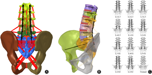
The CT images of the lumbar spine and pelvis were collected from a healthy volunteer (male, 26 years old, 176 cm and 71 kg) without any spinal disease. The participant provided informed written consent for this study. Mimics 20.0 (Materialise, Leuven, Belgium), Geomagic Studio 2012 (Geomagic, Cary, NC, USA), Solidworks 2017 (Dassault Systèmes, Limonest, France) and HyperMesh 2017 (Altair Technologies Inc., Fremont, CA, USA) were used to develop and mesh the FE model. The base of the FE model of the whole lumbar spine (L1-L5) was previously developed and validated.24 As shown in Figure 1, the model consisted of the whole lumbar spine (L1-L5), the pelvis and the related ligaments. Isotropic linear-elastic properties were assigned to vertebrae. The cortical bone, endplate, annulus matrix, and nucleus were meshed using hexahedral elements, while cancellous bone was meshed using tetrahedral elements. The thickness of the cortical bone was assumed to be 1 mm in the lumbar spine and 0.8 mm in the pelvis. The facet joints were defined as frictionless contacts.25 Six layers of annular fibers, meshed as nonlinear truss elements with no compression, were added to the annular matrix. The following ligaments were meshed as nonlinear truss elements with no compression: anterior longitudinal ligament (ALL); posterior longitudinal ligament (PLL); capsular ligament (CL); ligamentum flavum (IL); interspinous ligament (ISL); supraspinal ligament (SSL); transverse ligament (TL); anterior sacroiliac ligament (ASL); long posterior sacroiliac ligament (LPSL); short posterior sacroiliac ligament (SPSL); sacrospinous ligament (SS); sacrotuberous ligament (SL); interosseous sacroiliac ligament (ISIL); pubic ligament (PL); and iliolumbar ligament (IL). The attachment regions of the ligaments were obtained from previous studies.26 In total, the FE model contained 617,433 nodes and 2,345,421 elements. The material properties of the FE model were obtained from previous studies27-29 and are shown in Table 1.
| Component | Young's modulus (MPa) | Poisson's ratio | Stiffness (N/mm) | References | |
|---|---|---|---|---|---|
| Cortical bone | 12,000 | 0.3 | - | 27 | |
| Cancellous bone | 100 | 0.2 | - | 27 | |
| Bone endplate | 12,000 | 0.3 | - | 27 | |
| Cartilage endplate | 25 | 0.25 | - | 27 | |
| Annulus ground substance | 4.2 | 0.45 | - | 27 | |
| Nucleus pulposus | 1 | 0.4999 | - | 27 | |
| Anterior longitudinal ligament | 7.8 (<12.0%) | 20 (>12.0%) | 0.3 | - | 28 |
| Posterior longitudinal ligament | 10 (<11.0%) | 20 (>11.0%) | 0.3 | - | 28 |
| Capsular ligament | 7.5 (<25.0%) | 32.9 (>25.0%) | 0.3 | - | 28 |
| Ligamentum flavum | 15 (<6.2%) | 19.5 (>6.2%) | 0.3 | - | 28 |
| Interspinous ligament | 10 (<14.0%) | 11.6 (>14.0%) | 0.3 | - | 28 |
| Supraspinal ligament | 8 (<20.0%) | 15 (>20.0%) | 0.3 | - | 28 |
| Transverse ligament | 10 (<18.0%) | 8.7 (>18.0%) | 0.3 | - | 28 |
| Anterior sacroiliac ligament | 700 | 28 | |||
| Long posterior sacroiliac ligament | 1000 | 28 | |||
| Short posterior sacroiliac ligament | 400 | 28 | |||
| Sacrospinous ligament | 1400 | 28 | |||
| Sacrotuberous ligament | 1500 | 28 | |||
| Interosseous sacroiliac ligament | 2800 | 28 | |||
| Pubic ligament | 500 | 28 | |||
| Iliolumbar ligament | 1000 | 28 | |||
| AF layer 1 | 550 | 0.3 | - | 29 | |
| AF layer 2 | 495 | 0.3 | - | 29 | |
| AF layer 3 | 440 | 0.3 | - | 29 | |
| AF layer 4 | 420 | 0.3 | - | 29 | |
| AF layer 5 | 385 | 0.3 | - | 29 | |
| AF layer 6 | 360 | 0.3 | - | 29 | |
| Screw and rod | 110,000 | 0.3 | - | 29 | |
- Abbreviation: AF, annulus fibers.
FE Models of Fixation
Twelve kinds of models were constructed by implanting screws bilaterally. The intact model was the base model without surgery, and the 11 fixation models were established: (i) four models with the lowermost instrumented vertebra (LIV) of L5, including the L1-L5, L2-L5, L3-L5, and L4-L5 fixation models; (ii) five models with LIV of S1, including the L1-S1, L2-S1, L3-S1, L4-S1, and L5-S1 fixation models; and (iii) two models with LIV of S2, including the L1-S2 and L2-S2 fixation models. The surgery models were fixed by the posterior fixation system, which consisted of L1-S1 pedicle screws, S2 alar-iliac (S2AI) screws and connection rods. Hexahedral elements were used to mesh the screws and rods. The screws and rods were made of Ti6Al4V. The lengths of the pedicle screws and the S2AI screws were 55 and 110 mm, respectively, and the diameters of the screws and rods were 5.5 mm and 5 mm, respectively. The insertion points of the pedicle screws were positioned in the lateral and inferior corners of the superior facet joints. S2AI screws were inserted into the sacrum at the midpoint between the lateral points of the S1 and S2 foramina. The ipsilateral screws were connected by longitudinal rods. It was hypothesized that bone adhesions developed between the bone and screw, which prevented the implant from moving. Therefore, the contact between the screws and rods and the contact between the screw and the surrounding bone was assumed to be a no-slip interface,30 and the threads of the screw were ignored.
Boundary Conditions
The bilateral acetabulum was constrained in all six degrees of freedom to emulate the standing position. The node O positioned at the center of the sacrum was constrained in the three translational degrees of freedom and was connected to the superior surface of the L1 vertebra by a rigid rod that was extensible in length but constrained in three rotational degrees of freedom. The weight of the upper body was simulated by a 400 N compressive follower load on the superior surface of the L1 vertebra. Then, node O was rotated 10° in flexion, bending, extension and torsion to simulate the range of motion of the lumbar spine after surgery.
Data Analyses
The stress on the SIJ and at each level of the intervertebral disc were used to evaluate the biomechanical effects on these areas after internal fixation procedures, which is related to the risk of degeneration. The stress on the screws and rods was calculated to evaluate the risk of instrument failure.
Model Validation
The load–displacement curve measured by Miller et al. in a cadaveric study was used to validate the FE model of the sacrum.31 To simulate the previous experiment, each ilium was fixed, and the node on the midpoint of the superior sacral endplate was assumed to be the reference point for displacement. Five translational loads (anterior, posterior, superior, inferior and mediolateral) of 294 N and three rotational moments (flexion, extension, and axial rotation) of 42 Nm were applied to the point on the center of the sacrum. The displacement points of the reference points were compared with Miller et al.'s study.
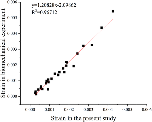
The FE model of the pelvis was also validated using the average strain values from the cadaveric study by Hu et al.32 The nodes on both acetabula were fixed, and vertical forces of 100, 200, 300, 400, and 500 N were applied on the top surface of the sacral vertebral body. As shown in Hu et al.'s study, six points on the surface of the pelvis, which were located along the pelvic biomechanical load transferring path, were selected as the measuring points. The strain of the measuring points was recorded and used for validation. compared with a previous study.
Results
Validation of the FE Model
As shown in Figure 2, the results of the FE model were compared with previous studies via linear regression analysis. The comparison of sacral displacements under the eight loading conditions showed satisfactory agreement with previous studies.31, 33

The R2 represented the correlation of the regression equation.
A comparison of the displacements and the regression equation showed that the finite element model agreed well with the experimental results (Figure 3).
Stress Distribution on the SIJ
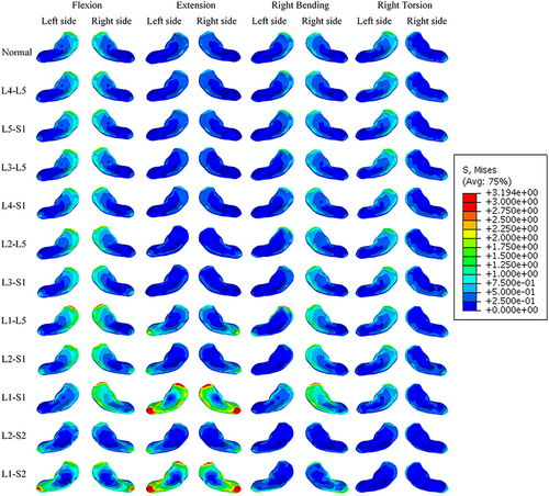
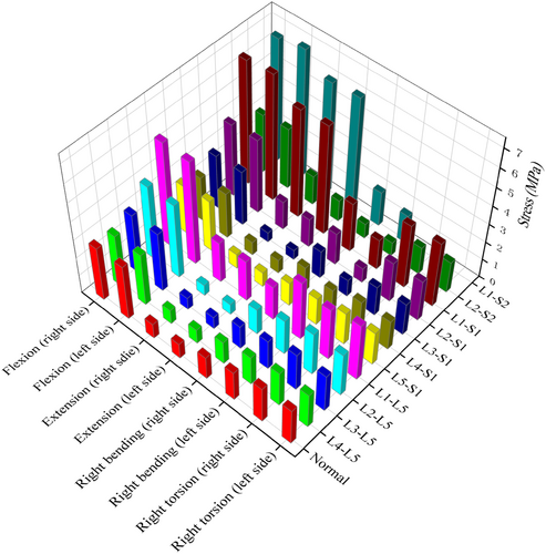
The distribution of the von Mises stress on the SIJs is shown in Figure 4. The stress was concentrated in the anterior part of the SIJ during flexion and was concentrated in the posterior part of the SIJ during extension. In the right bending motion, the stress on the right SIJ was greater than that on the left SIJ and was more concentrated in the anterior part. In the right torsion motion, the stress on the left SIJ was greater than that on the right SIJ and was more concentrated in the anterior part. The peak stress on the SIJs is shown in Figure 5. With the same LIV, the peak stress on the SIJs increased with the number of fixed segments. Among all the loading conditions, flexion led to the highest von Mises stress on the SIJs, which indicated that flexion was the worst-case loading condition.
Peak Stress on the Intervertebral Discs and SIJs
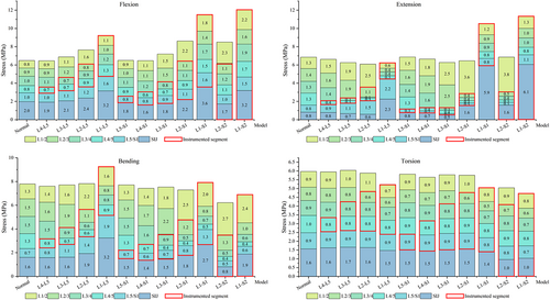
Figure 6 showed the peak stress on the intervertebral discs and SIJs in the normal and fixation models. Compared with the normal model, models with flexion motion showed lower peak stress on the SIJs in the L4-L5, L5-S1, L4-S1, L3-S1 and L2-S2 fixation models. The peak stress on the SIJs in the other flexion models was greater than that in the normal model. With extension, the peak stress on the SIJs decreased in the L4-L5, L3-L5, L2-L5, L5-S1, L4-S1 and L3-S1 fixation models. With bending motion, the peak stress on the SIJs was reduced in the L4-L5, L5-S1, L4-S1, L3-S1 and L2-S2 fixation models. With torsion motion, the peak stress on the SIJs was reduced in the L2-S2 and L1-S2 models, and there were no large differences in the peak stress on the SIJs in the models with LIVs of L5 or S1. Compared with the normal model, the peak stress on the fixed segments was reduced in the model with fewer than two fixed segments, and it increased on some of the fixed segments in the model with more than four fixed segments. The stress on the segment adjacent to the fixed segments was significant higher compared to that in the intact model.
Peak Stress on the Screws and Rods
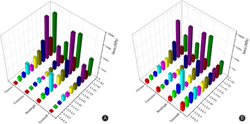
As shown in Figure 7, with the LIV of L5 or S1, the peak stress on the rods and screws increased with the number of fixed segments in the flexion, extension and bending motion. Peak stress on the screws and rods in the S1 involved group was greater than that in the L5 involved group. Among all the loading conditions, the bending motion led to the highest von Mises stress on the SIJs, followed by the flexion motion. Under torsion conditions, the number of fixed segments slightly influenced the peak stress on the screws. Unusually, the peak stress on the screws and rods in the L2-S2 fixed model was noticeably lower than that in the L2-S1 and L1-S2 fixed models.
Discussion
This study developed a lumbar-pelvis finite element model and evaluated the effects of multi-segments segments on the SIJs and lumbar spine. A significant correlation between the number of fixation segments and the stress on the SIJs and lumbar spine was found in the present study. Short-term fixation did not increase the stress on the SIJs, and long-term fixation increased the stress on the SIJs significantly. The peak stress on the upper adjacent segment and the fixation system increased with the number of fixed segments. The flexion motion led to the greater von Mises stress on the SIJs among the four kinds of motions.
Model Validation
It was necessary to verify the effectiveness of the model before evaluating the biomechanical effects of the multi-segment fixation. However, Hammer and Klima reported that most of these studies lacked cadaveric validation in a standardized manner.34 Most of these studies performed validation based on Miller et al.'s cadaveric study.35, 36 In the present study, the FE model of the pelvis was validated by linear regression analysis to compare the strain on the pelvis with the specimen mechanical experiment from Hu et al.'s study.32 The correlation coefficient of 0.967 indicates a strong correlation between the FE model and the experimental results and demonstrates that the model and boundary conditions are able to simulate the load transmission.
Biomechanical Effects of Multi-segments Fixation on the SIJs
The biomechanical factor was widely accepted as one of the potential causes of SIJ degeneration.37 The SIJ was the joint proximate to the distal end of the spine axis and distributes the load from the upper body. It was a significant purpose of the FE method to assess the relationships among lumbar fixation, stress on SIJs, rods and screws, displacement of the pelvis and to further predict the outcomes of lumbar fixation procedures. Ha et al.38 reported that 75% patients who underwent fusion had SIJ degeneration, and 38.2% in the healthy control group had this type of degeneration according to CT images. DePalma et al.12 reported that the prevalence of SIJ pain in patients who underwent lumbar spine fusion was 18.2%, and that in patients who underwent sacrum fusion was 12.8%. Nessim's study39 suggested that multi-segments fixation resulted in an increased risk of SIJ dysfunction as a larger portion of the spine was fixed causing increased mobility in adjacent segments which then bore additional stress. However, it is difficult to evaluate the biomechanical effects of lumbar fixation in clinical studies.
Although the SIJs are firm joint connecting the sacrum and ilium, previous studies have reported that the SIJ showed a rotation movement of approximate 4° and a translation movement of approximate 1.6 mm.40 As the SIJs have a sinusoidal or propeller-shaped form,6 the movement of different parts of the SIJs varies. In the present study, the stress distribution indicated that there was a greater risk of degeneration in the anterior part of the SIJs. Stress on the SIJs was concentrated in the anterior part during flexion, bending and torsion, and it was concentrated in the posterior part during extension. Shibata et al.41 reported that sclerosis commonly occurs on the anterior part of the SIJ, which was consistent with the results of this study.
Biomechanical Effects of Differences in the Number of Fixed Segments on Adjacent Segments
It was commonly believed that the stress on adjacent segments increases after fixation procedures in the lumbar spine.42 In the present study, the stress on the L5/S1 intervertebral disc increased with the number of fixed segments in the models with the LIV of L5, which showed that more fixation segments were related to greater stress on the adjacent lumbar segment. However, although the SIJ was close to the L5/S1 segment, there were some differences between the SIJs and intervertebral discs. In the short-term fixation (≤2 segments) models, additional L5/S1 fixation decreased the peak stress on the SIJs. However, the peak stress on the SIJs in the L1-S1 fixation models was greater than that in the L1-L5 fixation models. Additional L5/S1 fixation extended the fixation segments and increased the stress on the upper adjacent segment. With flexion, extension and bending motion, the stress on the SIJ with fewer than three fixed segments did not visibly change, while it increased noticeably with long-term fixation (≥4 segments). The stress on the SIJ was almost unaffected by the presence of fixed segments with torsion motion.
Biomechanical Effects of Multi-segment Fixation on the Fixation System
As the S2AI screw fixes the SIJ, S2AI fixation also differed from lumbar and lumbosacral fixation. In the L2-S2 fixation model, the stress on the SIJs decreased greatly, while the stress on the L1/2 increased noticeably. In the models without S2AI screws, the stress on the SIJs was extremely high in the models including L1-L5 fixation. Although Ha et al.38 indicated that all lumbar fixation had a relationship with the SIJ degeneration, the present study showed that the remaining mobile lumbar segments were also important. If the loss of range of motion (ROM) could be compensated for by short-term fixation, the flexion surgery would not lead to an obvious increase in the stress of the SIJs. When the rest of the mobile segments were too short, the SIJs would withstand greater deformation to complete motion, which led to high stress on the SIJs. Not considering the motion of the thoracic spine, three mobile lumbar segments were sufficient to compensate for light postoperative activity.
A high peak stress on the screws and rods might lead to screw loosening and rod fracture. Obviously, the peak stress on the screws or rods increased with the number of fixed segments with the same LIV (L5 or S1). However, the S2AI screws showed some differences. The peak stress on the rods and screws in the L2-S2 fixation model was less than that in the L2-S1 fixation model, and the peak stress on the rods and screws in the L1-S2 fixation model was less than that in the L1-S1 fixation model. The SIJ was much more stable than the lumbar intervertebral joint. S2AI fixation had little effect on axis stability; however, it decreased the peak stress on the fixation system. As the stress on the L1/L2 disc in the L2-S2 fixation model was slightly greater than that on the L1/L2 disc in the L2-S1 fixation model, surgeons needed to decide whether extending fixation segments was necessary.
Strengths and Limitations
Most previous FE analyses simulated the biomechanical behavior of the lumbar spine and pelvis under a certain compressive force and moment, for example, 400 N and 10 Nm.19, 33 However, after long segmental fixation, the patient's lumbar spine with the restraint device only exhibited a limited range of motion. The stress on the SIJs was highest during flexion motion among the four loading conditions in all fixation models and the normal model, which meant that the flexion motion led to the greatest burden.43 In addition, flexion was the most commonly used daily action. As a result, strict constraints in flexion motion were more effective at decreasing the risk of implant failure in the postoperative period. Based on these models and boundary conditions, the similarities and differences between sacroiliac fixation and lumbar fixation and their biomechanical changes of the spine and SIJs were systematically investigated in this study. In particular, the effects on the spine and SIJs with the LIV of L5, S1 and S2 were studied with the fixed segments extending upward.
The present study had several limitations. First, as many kinds of implants with different materials were used to fuse the operative segments,44, 45 the operative segments were only fixed with no fusion in this study. Second, the ROM of the thoracic spine was not taken into consideration in this study. As the thoracic spine is much more stable than the lumbar spine, there is slight movement in the thoracic spine, which might have affected the numerical value of the results. Third, the geometry of the SIJ varies anatomically among individuals.46 Only one FE model was employed in this study, which means that the simulation results might not be representative of everyone. In addition, this study simulated early postoperative conditions in which the motion of the spine was restricted by the device. However, the principal effects of changes in the boundary conditions and material properties of the intervertebral disc during long-term recovery have not been simulated. And the material parameters used in different components referred to the previous studies.27-29 The different material properties are adopted by other literature.47-50 Due to slight differences in mechanical properties, the calculated stress or deformation values might differ, but the trends of change were not affected.
Conclusion
Although the SIJs are an extension of the lumbar spine involved in the transmission of load to the lower extremities, the biomechanical characteristics of the SIJs differ from those of the lumbar segment after fixation. With short-term fixation (≤2 segments), the loss of ROM is completely compensated by the lumbar spine, which do not increase the stress on the SIJs. However, with long-term fixation (≥4 segments), the stress on the SIJs increases significantly, especially when the L1-L5 segments are all fixed. These results show that the lumbar segments compensate for the loss of ROM prior to the SIJs, and preserving some of the ROM of the lumbar spine can decrease the risk of SIJ degeneration.
Funding Information
The study was supported in part by National Natural Science Foundation of China (No. 82172483 to Xinyu Liu and 82102522 to Lianlei Wang) and Natural Science Foundation of Shandong Province (ZR2022QE287 to Hongwei Wang).
Author Contributions
Geng Zhao, Lianlei Wang, and Hongwei Wang carried out the entire procedure including the study design, data extraction, statistical analysis, manuscript writing and editing. Xinyu Liu and Lianlei Wang conceived the study, coordinated and participated in the entire process of drafting and editing the manuscript. Chao Li contributed to the data extraction, and statistical analysis. Suomao Yuan, Junyuan Sun, and Yonghao Tian contributed to the study design and data review. All authors have contributed significantly. All authors read and approved the final manuscript.
Consent for Publication
The authors agree to publication. This manuscript has not been published in any other journal.


