Advancements in Chemical Vapor Deposited Carbon Films for Secondary Battery Applications
Abstract
Carbon films, synthesized via chemical vapor deposition (CVD), have gained significant attention in secondary battery applications, where stability and capacity are required to be improved for next-generation electronic devices and electric vehicles. Beyond the inherent properties of carbon films, such as high electrical conductivity, mechanical strength, chemical stability, and flexibility, the CVD method provides a high degree of freedom in designing the carbon films in battery applications, enabling conformal coating with structure engineering for modification of its electrical and mechanical properties. In this review, the CVD-grown carbon films are highlighted in the secondary battery applications, enabling them to overcome critical issues, such as volume expansion, sluggish kinetics, and unstable interfaces. To deeply understand the CVD-grown carbon films, such as graphene and amorphous carbon, a comprehensive overview of the CVD process is also provided, focusing on growth mechanisms, control of 3D morphology, and doping techniques. In addition, a broad range of applications are introduced for carbon films in battery components, including their use in cathodes, anodes, and current collectors, as well as their potential in advanced battery systems, such as lithium-sulfur and all-solid-state batteries. This review proposes future directions for optimizing carbon films to achieve practical applications in next-generation energy storage devices.
1 Introduction
In recent decades, the secondary battery industry has rapidly expanded due to the high demand for portable electronic devices and electric vehicles.[1] However, the need for improved performance is increasing even more rapidly,[2] particularly regarding specific energy density, fast charging capabilities, and cycling stability. To satisfy these demands, recent research has primarily focused on improving interface reactions.[3-6] The most commonly adopted approach to enhance interface reactions has been the uniform modification of the interface with various interfacial materials, such as ceramics (oxides, phosphates, etc.)[7-10] or conductive polymers.[11-13] Additionally, complex structures of these materials, including vertically aligned[14, 15] and 3D porous structures[16-20] have been proposed. Among these interfacial materials, carbon-based materials have gained attention as a promising option because of their ease of processing, lightweight nature, chemical stability, and high electrical and ionic conductivities.[21, 22] However, fabrication of carbon films with complicated structures using conventional wet-chemical or solid-state reaction methods is still challenging.[23]
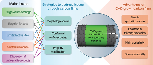
In contrast, the chemical vapor deposition (CVD) technique offers significant advantages over the conventional methods, allowing for the fabrication of uniform, high-quality carbon films in a more straightforward, scalable, and environment-friendly way.[24-26] Moreover, carbon films with complex structures can be created by CVD, along with ease in modification of their characteristics and high versatility in process for advanced applications.[27-31] Therefore, numerous studies have focused on utilizing CVD-grown carbon films in secondary battery applications by addressing critical issues, such as volume expansion of cathode/anode materials[32-34] and sluggish kinetics[35-37] (summarized in Figure 1). Nevertheless, it remains unclear whether high-quality, uniform carbon materials can be successfully grown on the active materials of cathodes and anodes, and further research is needed to understand the mechanisms behind the resulting battery performance improvements. Additionally, more studies are required to explore how the characteristics of carbon materials, such as crystal structure, defects, functional groups, and specific surface area, can be controlled and how this control can further enhance battery performance.
In this review, we explore the application of carbon films fabricated through CVD in various components of secondary batteries, including cathodes, anodes, and current collectors. The unique functional properties of carbon films, such as high electrical conductivity and structural stability, have been exploited to address key challenges in these battery components, thereby enhancing their electrochemical performance. In addition to traditional Li-ion batteries (LIBs), we discuss the potential of CVD-grown carbon films in advanced battery systems like lithium-metal batteries (LMBs), lithium-sulfur (Li-S) batteries, all-solid-state batteries (ASSBs), and lithium-oxygen (Li-O2) batteries. Despite these advancements, further research is needed to fully understand the growth mechanisms and to establish clear correlations between the structural and chemical properties of carbon films and their performance in different battery chemistries.
2 Fundamentals of CVD for Fabrication of Carbon Films
2.1 Working Principles of CVD and Processing Parameters
CVD involves introducing gaseous precursors including carbon sources into a reaction chamber, then those are decomposed and deposited onto a target substrate. The growth of carbon films through CVD is influenced by various processing parameters, such as gaseous precursors,[38] gas flow rates,[39, 40] temperature,[41] pressure,[42] and substrate material.[43] By fine-tuning these parameters, carbon films with tailored properties can be produced, which is crucial for enhancing battery performance. As illustrated in Figure 2a, gaseous precursors, such as CH4, C2H4, and C2H2, are introduced into the reaction chamber and flow over the substrate. The activation and decomposition of these precursors are driven by thermal or plasma energy. Then carbon species adsorb on the substrate, followed by dehydrogenation. A catalytic substrate facilitates the dehydrogenation of carbon species adsorbed on the surface, requiring less energy compared to a non-catalytic substrate. Depending on the carbon solubility of the substrate, the carbon species either migrate over the surface to form graphene nuclei or dissolve into the bulk, followed by segregation during the cooling step.[28]

The structure and properties of carbon films grown by CVD are significantly influenced by the substrate used as a growth template due to different growth modes (Figure 2b).[43, 44] In self-limited growth, an efficient catalytic metal, Cu, is used for the decomposition of hydrocarbon gas. Because Cu has extremely low carbon solubility even at high temperatures, graphene is grown in a self-limited way. Growth of thicker graphene is inhibited due to the pre-formed graphene layer acting as a barrier to contact additional carbon sources to the Cu surface.[45, 46] When Ni with high carbon solubility is used as a growth template, multilayer graphene is grown via precipitation and segregation of carbon atoms dissolved in Ni.[47, 48] The number of graphene layers can be controlled by adjusting the cooling rate and carbon concentration in the Ni substrate.[47] Similar to catalytic metal substrates, Al2O3 and MgO with high chemical activity effectively convert CH4 gas into monolayer graphene films.[49-51] In contrast to catalytic substrates, less-reactive substrates, such as SiO2, require higher energy to grow graphene and deposit carbon films, necessitating elevated temperatures or plasma energy.[52] However, due to the required high energy and non-crystalline nature of SiO2, the synthesized carbon films on SiO2 show lower crystallinity and less controllability in film thickness. Nevertheless, it has been reported recently that the quality of carbon films grown on SiO2 can be improved by fine-tuning growth conditions, such as temperature and gas flow rate,[53, 54] introducing H2O or Cu vapor to facilitate nucleation of graphene,[55, 56] or modifying the substrate surface.[57-60]
However, a conventional CVD process requiring high temperatures is not appropriate for non-catalytic and chemically unstable cathode and anode materials used in secondary batteries. Thus, plasma-enhanced CVD (PECVD) has been employed for battery materials as it enables the growth of carbon films at low temperatures on non-catalytic substrates while minimizing the degradation of battery materials. (Figure 2c).[31] Although plasma energy enhances the decomposition and adsorption of carbon species on the target surface, low processing temperature in the PECVD process limits surface migration of adsorbed carbon species, potentially degrading the crystallinity of the carbon films (Figure 2d).[61] However, it is important to emphasize that optimizing the growth conditions of carbon films is not sufficient; controlling the quality aspects, such as crystal structure and thickness, is crucial for enhancing battery performance. This ensures efficient penetration of Li ions and prevents degradation of battery materials, as well as the uniform formation of a solid electrolyte interphase (SEI) on carbon films.
2.2 Morphology Control of Carbon Films
The morphology of carbon film plays a critical role in their performance in batteries, particularly in influencing the electrode surface area, ion transport pathways, and mechanical stability. In this regard, carbon films with different morphologies, such as sheets, vertically aligned walls, shells, and foams, have been used as shown in Figure 3. Carbon film morphology is primarily determined by the morphology of the substrate used during CVD synthesis. Carbon sheets are typically grown on flat substrates such as metal foils, resulting in ultra-thin, 2D films. Shell structures, on the other hand, are synthesized on particle-like cores, where the carbon film conforms to the spherical shape of the core. Foam structures are created by growing carbon films on complex, porous templates like Ni foam, which imparts a 3D interconnected morphology. For vertically aligned wall structures, specific CVD conditions, such as the use of PECVD, are critical to promoting vertical growth.
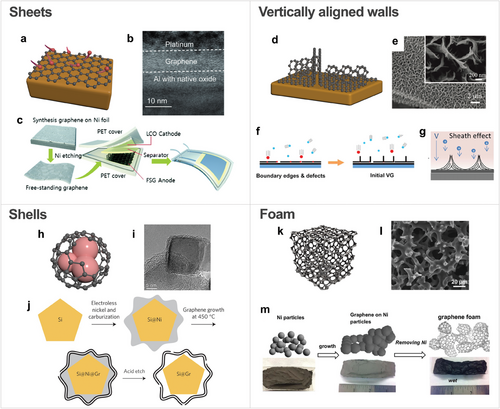
Carbon sheet, synthesized through CVD on flat substrates, has a thickness ranging from a few angstroms to a few nanometers (Figure 3a). Carbon sheet is particularly effective in preventing the degradation of battery materials, while also enhancing electron transport. For example, the nanometer-scale carbon sheet in Figure 3b has been used to coat current collectors, effectively preventing corrosion.[62] In battery applications, direct CVD growth of graphene on thermally sensitive materials, such as polymer separators, is challenging. High-quality graphene sheets with superior crystallinity grown on catalytic substrates like Cu can be transferred onto these sensitive materials (Figure 3c).[63, 64] This transfer method not only preserves the underlying materials but also allows the exploitation of outstanding properties of the carbon sheet.
Vertically aligned carbon walls consist of carbon layers grown perpendicular to the substrate (Figure 3d,e), offering a high surface area with open edges that provide active sites for ion storage and fast charge transfer, improving the capacity of the electrode and kinetics of the battery system.[65] Vertically connected walls also enhance electrical conductivity through contact between active materials. As depicted in Figure 3f, high strain at boundary edges and defects during the CVD process leads to vertically orientated growth of carbon films.[66] It has been reported that the PECVD is advantageous for growing vertically aligned carbon walls since the plasma sheath accelerates the energetic ions, impacting the substrate surface and creating defects that promote vertical growth (Figure 3g).[67] The morphology of vertically aligned carbon films can be controlled by adjusting growth conditions, such as plasma power, growth time, and temperature, which results in different combinations of the deposition and etching effects. Generally, the plasma power, growth temperature, and time determine the number of branches, the thickness of carbon layers, and the height of vertical carbon walls, respectively.[66] These parameters collectively govern the balance between deposition and etching effects, which are critical for achieving the desired morphology.
Carbon shells in Figure 3h,i encapsulate a core material.[68] This structure has advantages not only in the protection of core materials from degradation but also in accommodating volume expansion during cycles, thereby improving cycling stability. In addition to core–shell structures, where core particles are directly covered by a shell, Yolk–shell structures, where core particles are encapsulated by a hollow shell, prevent the aggregation of active materials and their volume expansion, facilitating the transport of electrons and Li ions.[69] To fabricate Yolk–shell structures with void space between the core and shell, an etching process is required to remove the sacrificial coating layer after the carbon film is deposited by CVD (Figure 3j).[70] As a sacrificial layer, Ni has been used since it can be uniformly deposited on the core materials, and multilayer graphene with high crystallinity can be grown on it. Moreover, Ni can be selectively etched with acid without damaging the carbon film.
Carbon foam is a 3D porous architecture consisting of interconnected carbon films, typically grown by CVD on a metal foam template, such as Ni foam (Figure 3k,l).[71] With its high surface area and enhanced electron transport afforded by the complex morphology, carbon foam provides superior mechanical strength, enabling free-standing electrodes without the need for binders or conductive additives. Its well-developed interconnected framework supports active materials, preventing the aggregation of nanoparticles and accommodating their volume expansion during charge and discharge cycles.[72] To fabricate the structure, after the growth of carbon film on metal foam, the metal foam is removed through chemical etching, leaving behind free-standing carbon film-based foam (Figure 3m).[73]
2.3 Doping Strategies of Carbon Films
Doping is a crucial technique for modifying the electronic properties of carbon films. The CVD method provides precise control over the in situ doping process, enabling the incorporation of heteroatoms, such as N, B, or S, into the carbon lattice. During the CVD process, dopant precursors can be introduced along with the carbon precursor gas. The dopant atoms integrate into the carbon films as they form, resulting in a uniform distribution. The benefits of heteroatom doping include: 1) Enhanced electrical and ionic conductivities, 2) Surface modification, 3) Fabrication of active sites, and 4) Enlarged interlayer spacing.
Heteroatom doping significantly enhances both electrical and ionic conductivities in carbon film. The doping of foreign atoms introduces additional charge carriers, thereby increasing the density of current carriers and enhancing the electrical conductivity of the carbon films.[74, 75] Doping also alters the surface charge distribution and introduces lattice defects, which facilitate ion diffusion, thereby enhancing ionic conductivity. Heteroatom doping is also a powerful tool for surface modification, optimizing surfaces for specific battery chemistries. For example, in Li-S batteries, doping creates sulfiphilic surfaces, improving the kinetics of polysulfide transformation and mitigating the shuttle effect.[76] For this, B and N are co-doped during the CVD process from boraic acid and melamine (Figure 4a). In Zn-ion batteries, heteroatom doping creates zincophilic surfaces, leading to uniform Zn nucleation and the suppression of side reactions.[77, 78] Similarly, in Na and K metal batteries, surface modification via heteroatom doping facilitates homogeneous sodium/potassium deposition, which effectively prevents the formation of dendrites and enhances cycling stability.[79, 80]
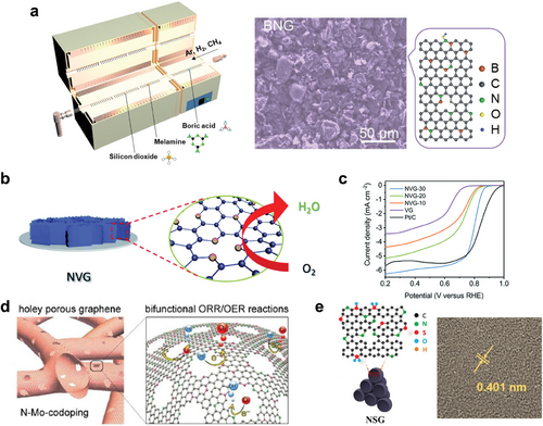
Additionally, doping introduces numerous active sites in carbon film. In Li-S batteries, the active polar sites created by doping in the carbon films facilitate the chemical adsorption of lithium polysulfides, thereby suppressing the shuttle effect.[81] Furthermore, the Li storage capacity of graphite-based anodes is enhanced by doping foreign atoms into graphene, which provides additional active sites.[82] In metal–air batteries, heteroatom-doped carbon film with abundant active sites improves the catalytic effect for the oxygen evolution reaction (OER) and oxygen reduction reaction (ORR). By introducing N2 gas during the PECVD process, N-doped vertical graphene nanosheets were synthesized for Zn–air battery cathodes (Figure 4b).[83] The defective structure, with optimal N doping and plentiful exposed edges, provides numerous active sites for the ORR (Figure 4c). Similarly, N and Mo co-doped nanoporous holey graphene exhibits high bifunctional ORR and OER catalytic activity, serving as an effective air electrode in Zn–air battery (Figure 4d).[84] In addition to heteroatom doping, the introduction of defects in carbon film is a highly effective strategy for increasing the number of active sites in carbon films, further improving their electrochemical performance in battery systems. Defects, such as vacancies, edge sites, and grain boundaries, act as catalytic centers, facilitating various electrochemical reactions and enhancing ion adsorption and diffusion.[85, 86] These defects can be introduced and tailored through various defect engineering techniques, including plasma treatment or high-temperature annealing, allowing precise modulation of the defect density and distribution to optimize performance for specific battery applications.[87]
The interlayer spacing in carbon film is a critical parameter affecting the storage and transport of larger ions, such as Na⁺ and K⁺, in Na-ion and K-ion batteries. Heteroatom doping effectively enlarges the interlayer spacing, creating more room for ion insertion and improving the storage capacity of these batteries. For example, N and S co-doped graphitic hollow architectures show an enlarged interlayer spacing of 0.401 nm, which is highly favorable for K ion intercalation in K-ion battery anodes (Figure 4e).[88] This, combined with ample surface defects and active sites, enhances reaction kinetics, resulting in high-rate capability and long cycle life.
3 Carbon Films for Cathode, Anode, and Current Collector in Alkali-Ion Batteries
The following sections mainly focus on the application of carbon films to key components of Li, Na, and K-ion batteries: cathode, anode, and current collectors. The carbon films synthesized via CVD have been utilized for these components, leading to significant improvements in the electrochemical performance of secondary batteries.
3.1 Carbon Films in Cathode
In secondary batteries, the cathode material plays a critical role, as it not only supplies charged species during charge and discharge but also determines the operating voltage, which increases with the voltage of the cathode material.[89] However, the detrimental side reactions at the cathode/electrolyte interface the one of the major causes for the degradation of cathode materials. Ni-rich layered oxides, such as LiNixCoyMnzO2 (NCM, where x + y + z = 1), face several challenges, including surface reconstruction during repeated charge–discharge cycles due to similar ionic radii of Ni2+ and Li+. Moreover, unstable Ni3+ or Ni4+ easily reacts with liquid electrolyte to evolve gaseous species, such as CO2 or H2O.[90-94] Mn-containing cathode materials, such as LiMn2O4[95, 96] and LiMnxFe1-xPO4,[97-99] commonly experience the dissolution of Mn2+ ions into the organic liquid electrolyte, due to the disproportionation reaction of unstable Mn3+. Besides interfacial problems, low electrical conductivity is also an intrinsic limitation of most cathode materials.[100-102] Notably, the application of a conductive coating layer can address this issue as it not only blocks the direct contact between the cathode and electrolyte but also reduces the charge transfer resistance between particles to promote rapid electron transport.
The CVD process allowed us to deposit a thin and conformal carbon coating layer with high crystallinity in a simple way. However, the conventional CVD process for the deposition of carbon was not suitable for cathode, since most cathode materials become unstable at the high temperatures (800–1000 °C) typically required for graphene growth via CVD. Therefore, extensive research has focused on developing low-temperature CVD methods to deposit amorphous carbon films on cathode materials. The application of catalytic metals or plasma generators has enabled the complete coverage of the cathode with a carbon layer with satisfactory crystallinity and electrical conductivity, improving the performance of the cathode while avoiding thermal degradation.[103-107] It was reported that homogeneous carbon films grown on LiMn2O4 by low-temperature CVD conducted at 500 °C with C2H2 efficiently prevent the dissolution of Mn.[108] The formation of an amorphous carbon layer of ≈3 nm on LiMn2O4 was observed, while the LiMn2O4 still maintained its original spinel structure after the CVD process. It reflected that the hydrocarbon species was successfully decomposed and deposited on the cathode surface at a low temperature, avoiding the thermal degradation of LiMn2O4. By immersing the carbon-coated LiMn2O4 in an organic liquid electrolyte, the concentration of dissolved Mn ions was measured using inductively coupled plasma spectrometry (ICP). As shown in Figure 5a, the carbon-coated LiMn2O4 showed much lower Mn concentration compared to pristine LiMn2O4. A conformal and uniform carbon layer completely blocked the contact between LiMn2O4 and liquid electrolyte to reduce the dissolution of Mn ions and maintain the original crystal structure. This consequently enhanced the cyclic stability in the electrochemical test: Discharge capacity retention of carbon-coated LiMn2O4 was much higher than pristine LiMn2O4 after 100 cycles at 50 °C at 5 C (Figure 5b) since the carbon-coated sample was able to maintain its original spinel structure for longer cycles compared to the pristine sample. In addition, the rate-capability of carbon-coated LiMn2O4 electrodes in all C-rates from 0.1 C to 30 C was also improved (Figure 5c). An amorphous carbon coating layer with reasonable electrical conductivity contributed to efficient electron transport by constructing a conductive network between powders. Compared to amorphous carbon powders which are commonly utilized as conductive additives in a typical electrode fabrication process, a conformal carbon layer at the surface constructed a more efficient network throughout the electrode, leading to fast charge transfer and improved discharge capacity retention at high C-rates.
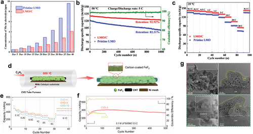
Conversion-type cathode materials, such as FeF2, have attracted lots of interest due to their high theoretical capacity compared to commercial layered or olivine cathode materials.[109] However, FeF2 also experienced undesirable reactions at the interface. It intrinsically suffers from sluggish electron or ion transport kinetics. Moreover, it undergoes a huge volume change of 17% during cycling, which leads to the formation of thick and non-uniform cathode solid electrolyte interphase (CEI), continuously consuming liquid electrolytes.[110-114] Despite the necessity of uniform surface treatment for FeF2, it was problematic to deposit a uniform carbon layer at high temperatures, since FeF2 is also easily degraded into side products, such as FexC, at high temperatures under hydrocarbon treatment. A catalytic Ni substrate was adopted to lower the temperature of hydrocarbon decomposition and the overall CVD process.[115] As a result, an amorphous carbon film of 0.98 nm thickness was successfully deposited uniformly on FeF2 at a low temperature of 500 °C, without any thermal degradation (Figure 5d). The effect of the amorphous carbon layer on the FeF2 cathode was investigated by both rate-capability and cyclic stability tests. The carbon-coated FeF2 showed higher discharge capacity when increased the current density from 0.1 C to 5 C (Figure 5e), evidencing the formation of an efficient network for electron transport, which resulted in lower polarization and enhanced reaction kinetics compared to pristine FeF2 cathode. It was also demonstrated that the carbon-coated FeF2 retained its initial discharge capacity for longer cycles compared to the pristine sample in the dilute electrolyte (Figure 5f). Postmortem analysis revealed that the formation of thick and non-uniform CEI, which is a significant bottleneck of conversion-type cathode with huge volume expansion, was successfully prevented in the presence of a surface carbon layer. Li-F signal was weaker in the cycled carbon-coated FeF2 sample compared to the cycled pristine FeF2 sample, proving the formation of thin CEI regarding the LiF is a major component of the CEI layer.[116] The presence of thin and uniform CEI was again proved in the cryo-transmission electron microscope (TEM) study, showing that the CEI of the cycled carbon-coated sample was much thinner and uniform compared to that of the cycled pristine sample (Figure 5g). The conformal carbon coating layer effectively prevented direct contact between the cathode and liquid electrolyte, significantly mitigating the aggressive reactions at the cathode surface.
It was reported that the hierarchical fibrous carbon films directly grown on Na3V2(PO4)3 (NVP) by the CVD process enhanced its performances for Na-ion battery application.[120] The CVD was conducted at 690 °C, which is relatively high due to the robust P─O bond, using C2H2 as a carbon source. The macroscopic structure of the final carbon films was unique. The thin and compact graphene-like layer with regular lattice fringes was observed at the surface of NVP. Furthermore, the carbon nanofibers were rigorously deposited on the graphene-like surface layer, establishing a hierarchical 3D structure (Figure 6a). The effect of carbon film with a hierarchical 3D structure was investigated at high C-rate conditions. The NVP with 3D carbon films was still capable of delivering a specific capacity of 38 mAh g−1 even at 500 C. Both high electrical conductivity and hierarchical 3D structure of carbon film contributed to the great capacity retention under high current density, by establishing a conductive network for electron conduction as well as shortening the length and time for Li-ion diffusion with high constant dimensionality of 6. Minimized peak splitting between oxidation and reduction peak of carbon-coated NVP compared to pristine sample was also observed in the cyclic voltammetry test, evidencing the lower electrochemical polarization and higher reversibility originated from fast electron and Li-ion conduction of hierarchical 3D carbon film.
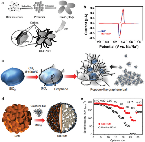
Meanwhile, carbon films with distinct macroscopic morphologies grown on other materials, such as Ni foam or oxides, other than the active materials were also capable of modifying the performance of cathode materials. These carbon films on other materials can modify the surface of the cathode through additional processes, such as hand mixing, ball milling, or wet chemical methods. Especially, the popcorn-like graphene balls applied to the surface of the Ni-rich layered cathode (LiNi0.6Co0.1Mn0.3O2 or NCM613) successfully modified its surface.[121] SiO2 nanoparticles served as a substrate for graphene growth to synthesize graphene balls, and the CVD was conducted at 1000 °C using CH4 gas as a carbon source (Figure 6c). Graphene balls uniformly covered the surface of the NCM613 cathode via simple ball-milling (Figure 6d) and even infiltrated into the gap between primary particles. The graphene balls with unique structures, which contain SiOx seed at their core, enable a uniform coating through a mild ball-milling process due to the shearing force between graphene balls and active materials. When fast charging characteristics were investigated for NCM613 with or without graphene balls, varying the charging rate from 0.1 C to 10 C (Figure 6e), NCM613 with graphene balls maintained higher capacity compared to pristine NCM613 in all C-rates, thanks to the high electrical conductivity of graphene layers. Furthermore, in terms of capacity fading, NCM613 with graphene balls showed better capacity retention at all different upper cut-off voltage conditions, from 4.3 to 4.5 V, not only at room temperature but also at elevated temperature. The stable cyclic performance of NCM613 in aid of graphene balls is attributed to the SiOx seeds in graphene balls that scavenge the detrimental HF species.[122]
To summarize, CVD parameters and electrochemical performances of alkali-ion battery cathodes based on CVD-grown carbon films are presented in Table 1. The application of carbon films to cathode materials has been shown to significantly enhance the electrochemical performances of secondary batteries. Despite the poor thermal stability of cathode materials, various types of carbon films, such as conformal carbon layers or carbon fibers, were simply synthesized by adjusting the experimental parameters of the CVD process. However, it should be noted that achieving conformal surface coverage is crucial for regulating detrimental side reactions at the interface, such as Mn dissolution or non-uniform formation of the CEI layer. In contrast, carbon fibers or graphene balls play an important role in improving reaction kinetics. However, the understanding of how the synthetic process, macroscopic structures, or properties of carbon films contribute to the enhancement of battery performance remains insufficient. For future progress, it is essential to identify the ideal design of carbon films that satisfy critical requirements, such as crystallinity, uniformity, and specific surface area, by optimizing the synthetic parameters to realize this balance.
| Type of battery | Active material | Carbon morphology | CVD parameters | Retention@cycle number [C-rate] | Retention at high current [low C-rate / high C-rate] | Refs. |
|---|---|---|---|---|---|---|
| Li-ion Battery | Li(Ni0.33Co0.33Mn0.33)O2 | Shell | 550 °C, 1 h, sucrose | 94.29%@100 (0.1 C) | 52.45% (0.1 C / 10 C) | [105] |
| Shell | 1200 W (2.45 GHz), 2 s, anthracene | 96%@40 (0.2 C) | 83.69% (0.5 C / 2 C) | [123] | ||
|
Li(Ni0.6Co0.1 Mn0.3)O2 |
Vertical | 1000 °C, 30 min, CH4 | 97.3%@100 (1 C) | 44.94% (0.1 C/10 C) | [121] | |
| LiMn2O4 | Shell | 500 °C, 5 min, C2H2 | 93.44%@2000 (20 C) | 59.55% (0.1 C / 30 C) | [108] | |
| Sheet (transferred) | 1000 °C, 1 h, CH4 | 90%@750 (100 mA/cm2) | 70% (100 mA cm−2 / 500 mA cm−2) | [124] | ||
| LiFePO4 | Shell | 730 °C, 10 h, CH4 | – | 76.8% (0.2 C / 10 C) | [125] | |
| Shell | 700 °C, 10 h, benzene | 91.8%@30 (0.1 C) | 73.7% (0.1 C / 5 C) | [126] | ||
| Shell | 550 °C, 1 h, glucose | 93%@500 (100 C) | 44.06% (0.1 C / 250 C) | [103] | ||
| Shell | 1000 W (2.45 GHz), 650 °C, 15 min, CH4 | – | 67.02% (0.1 C / 20 C) | [104] | ||
| Foam | 1000 °C, 2 min, CH4 | 99%@160 (1 C) | 68.75% (1 C / 24 C) | [16] | ||
| Foam | 800 °C, 15 min, C2H2 | 116.51%@100 (3 C) | 31.65% (0.1 C / 5 C) | [127] | ||
| Vertical | 1100 °C, 4 h, CH4 | 88.9%@1000 (1 C) | 56.32% (0.2 C / 10 C) | [128] | ||
| LiMnPO4 | Shell | 800 °C, 20 min, methylbenzene | 93%@50 (0.05 C) | 46.15% (0.1 C / 5 C) | [129] | |
|
LiMn0.8Fe0.2 PO4 |
Shell | 650 °C, 8 min, C2H2 | 80%@320 (1 C) | 88.08% (0.1 C / 5 C) | [106] | |
| V2O5 | Shell | 50 W, 500 °C, 15∼30 min, C2H2 | 65–67%@50 (0.1 C) | – | [130] | |
| Foam, Vertical |
1000 °C, 10 min, CH4 / 30 W, 750 °C, 20 min, C2H2 |
41.3%@1000 (5 C) | 40.76% (0.1 C / 10 C) | [118] | ||
| FeF2 | Shell | 500 °C, 3 min, C2H2 | 75%@2500 (0.5 C) | 56% (0.1 C / 5 C) | [115] | |
| Na-ion Battery | Na3V2(PO4)3 | Vertical | 690 °C, 20 min, C2H2 | 54%@20000 (30 C) | 33.93% (0.5 C / 500 C) | [120] |
| Na3V2(PO4)2F3 | Shell | 500 °C, 2 h, C2H2 | 86.5%@500 (0.2 C) | 48.06% (0.2 C / 10 C) | [131] | |
| Vertical | 680 °C, 30 min, C2H2 | 86.3%@5000 (20 C) | 73.6% (0.5 C / 50 C) | [132] | ||
| K-ion Battery | KVPO4F0.5O0.5 | Shell | 600 °C, 3 h, C2H2 | 88%@20 (0.2 C) | 54% (0.05 C / 10 C) | [133] |
3.2 Carbon Films in Anodes
Currently, graphite-based materials are commonly used as anodes in LIBs due to their reliable performance during charge and discharge cycles. However, conventional graphite anodes have limited capacity, driving research into alternative materials that offer much higher capacities. The performance of these alternative anode materials is often hindered by several issues, including slow electron and ion transport, and mechanical degradation due to volume changes during cycling. To overcome these challenges, extensive research has been conducted on using carbon films for anode materials, similar to the studies on cathode materials, with carbon films emerging as one of the most promising solutions.[22, 23, 134] Additionally, morphological engineering and structural modification by heteroatom doping through the CVD method offer significant potential for enhancing the performance of battery anodes.[135]
One of the largest issues in the anode materials is achieving fast electron and ion transport to facilitate rapid charge and discharge cycles. In general, most anode materials can withstand higher temperatures rather than chemically unstable cathode materials, facilitating easier growth of high-quality carbon film using high-temperature CVD processes. The quality of carbon film, particularly their crystallinity and the portion of sp2 hybridization, is closely linked to electrical conductivity because delocalized π-bonds increase in-plane conductivity.[136] Additionally, factors such as the number of layers, defect density, doping, and grain size also impact the electrical properties of carbon film.[86, 137] Therefore, optimizing these properties in carbon films can provide an effective solution for achieving fast electron transport. Similar to cathodes, 3D morphologies of carbon films in anodes can shorten the diffusion distance of ions, thus enhancing ionic conductivity. These morphologies also provide a stable electrical connection, preventing electrical isolation and contact loss of the electrode material.[138]
Vertical graphene not only improves the conductivity of the anode material but also ensures a stable conducting network through interconnected graphene during lithiation.[139] To improve the electrical conductivity of SiO microparticles-based anode, vertical graphene nanosheets were directly synthesized using CVD. A vertical graphene coating layer, with its large surface area, offers more electrical contact points compared to pristine SiO and horizontally coated graphene layers on disproportionated SiO particles (Figure 7a). Because of the significant reduction in contact resistance, the resistance of single SiO was greatly decreased from ≈4.0 × 10¹² Ω to ≈3.1 × 10⁴ Ω with the encapsulation of 2.5 wt.% graphene (Figure 7b,c). The vertical graphene structure increases the specific surface area and the electrode-electrolyte contact area, resulting in enhanced charge–discharge capacity (Figure 7d).
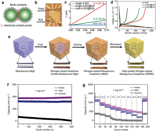
It is worth noting that, since carbon film itself can serve as an anode material in ion-intercalation energy storage systems, the CVD method, well suitable for morphological engineering and heteroatom doping, offers an effective strategy to enhance the capacity and electrochemical performance of carbon film-based battery anodes by providing additional Li-storage sites.[136, 140] Figure 7e shows the fabrication process of high-quality N-doped mesoporous graphene (HNMG) particles.[141] First, N-doped, mesoporous graphene (NMG) particles were prepared on a mesoporous MgO sacrificial template through CVD using the acetonitrile precursor, followed by an etching of the MgO template. Subsequently, HNMG particles were obtained by subsequent microwave radiation to reduce the defect density of the NMG. The mesoporous structure and reduced defect density of HNMG led to improved electrical conductivity and electrochemical stability, along with numerous Li-ion storage sites and enhanced ion transport. N doping during CVD also modifies the surface to become lithiophilic, providing uniform nucleation sites of Li ions for high-energy-density. The electrode prepared from HNMG particles with a mass loading of 1 mg cm−2 exhibits an initial discharge capacity of 945 mAh g−1, a charge capacity of 723 mAh g−1, and a Coulombic efficiency of 76.5% at a rate of 2 C which is significantly higher than graphite anodes (Figure 7f). In rate performance tests, the HNMG electrode demonstrates a reversible specific capacity whereas NMG shows significantly lower capacity. (Figure 7g). Even at a high charge–discharge rate of 60 C, the HNMG electrode maintains a reversible capacity of 448 mAh g−1, which is 3 times higher than that of NMG electrodes (163 mAh g−1), and 70 times higher than that of a graphite electrode (6 mAh g−1).
Among alloy-type anode materials, Si has been considered one of the most promising candidates for next-generation anodes due to its high specific capacity (4200 mAh g−1) compared to graphite (372 mAh g−1).[34, 142, 143] However, huge volume change (420%) during lithiation and delithiation makes it challenging to promptly utilize the Si as an anode material in LIBs.[33, 34, 143] Such a volume change leads to degradation of the Si anode, such as pulverization, detachment from the current collector, and formation of an unstable SEI layer, significantly reducing the cyclic stability of the battery (Figure 8a).[32, 142] To mitigate these issues, carbon coating on Si anode materials has been studied actively.[138, 144-148]

Similarly, metal oxide nanoparticles, such as Co3O4, were coated by graphene as shown in Figure 8b. The graphene shells were synthesized on 3 nm-scale Co3O4 nanoparticles via in situ CVD.[149] To synthesize the graphene-encapsulated Co3O4 nanoparticles, metal-organic precursors of CpCo(CO)2, Fe(C5H5)2, and (MeCp)2Ni were injected into a reactor, along with a carbon precursor of C2H5OH. The metal oxide, sulfide, or phosphide with graphene shells was synthesized through oxidation, sulfidation, or phosphidation under an atmosphere of oxygen, sulfur, or phosphorus, respectively. The conformally coated graphene shells minimized the volume expansion, preventing pulverization during lithiation while providing high electrical conductivity with minimal barriers for Li-ion transport. (Figure 8c). In the long-term cycle stability test, graphene-coated Co3O4 nanoparticles maintained a reversible capacity of 677 mAh g−1 after 2000 cycles (capacity retention of 82%) at 2000 mA g−1, indicating that the graphene shells significantly improved the cycle retention compared to pristine Co3O4 nanoparticles (Figure 8d).
CVD parameters and electrochemical performances of alkali-ion battery anodes based on carbon films are summarized in Table 2. CVD-grown carbon films offer significant benefits for battery anodes, including improved electrical and ionic conductivity, abundant active sites, and conformal coatings that reduce volume expansion. These enhancements boost the anode's kinetics, capacity, and stability. Key factors for achieving these benefits are the control of carbon film properties such as crystallinity, graphitization, thickness, defect density, doping, and morphology. Optimizing these aspects is crucial for advancing anode performance in energy storage systems.
| Type of battery | Active material | Carbon morphology | CVD parameters | Dopant | Retention@cycle number [C-rate] | Retention at high current [low C-rate / high C-rate] | Refs. |
|---|---|---|---|---|---|---|---|
| Li-ion Battery | Graphene | Foam (mesoporous) | 900 °C, 15 min, acetonitrile | N | 99.1%@3000 (60 C) | 38.66% (0.2 C / 60 C) | [141] |
| Foam | 1100 °C, 10 min, C2H4 | – | 99%@250 (0.1 C) | 15% (0.1 C / 4 C) | [150] | ||
| Si | Shell | 900 °C, 30 min, hexane | – | 75.7%@300 (0.5 C) | – | [137] | |
| Shell | 750 °C, 10 min, ethanol | – | 93%@100 (1 C) | 44.76% (0.1 C / 2 C) | [144] | ||
| Shell | 1050 °C, 10 min, CH4 | – | 77%@500 (0.5 C) | 36.55% (4 C / 10 C) | [148] | ||
| Shell, Vertical | 1050 °C, 2 h, CH4 | – | 91.5%@500 (1 C) | 14.29% (0.1 C / 20 C) | [138] | ||
| Shell, Vertical | 1050 °C, 15 min, CH4 | – | 33.48%@300 (1 A g−1) | 35.03% (0.1 A g−1 / 6 A g−1) | [145] | ||
| Foam, Vertical | 1 000–1300 °C, 3–6 h, ethanol | N, O | 94.5%@1500 (8 A g−1) | 29.26% (0.05 A g−1/10 A g−1) | [140] | ||
| SiO | Shell, Vertical | 950 °C, 2 h, CH4 | – | 80%@400 (1 C) | 94% (0.5 C / 5 C) | [139] | |
| Si/SiO2 | Shell | 1050 °C, 8 min, CH4 | – | 91%@290 (0.5 C) | 83.05% (0.2 C / 3 C) | [146] | |
| Si/C | Shell | 760 °C, 10 min, C2H2 | – | 75.2%@500 (0.5 C) | 80% (0.2 C / 5 C) | [147] | |
| Sn | Shell | 900 °C 10 min, acetonitrile | N | 100%@500 (0.2 A g−1) | 52.5% (0.2 A g−1 / 10 A g−1) | [151] | |
| Al | Shell | 1000 °C 30 min, CH4 | – | 48.8%@1000 (0.1 C) | 30% (0.1 C / 5 C) | [152] | |
| MnO | Sheet (transferred) | 1000 °C, 10 min−1 h, CH4 | – | 98.69%@200 (0.15 C) | 37.4% (0.05 C / 20 C) | [86] | |
| Co3O4 | Shell | 400–700 °C, ethanol | – | 82%@2000 (2 A g−1) | 59% (0.1 A g−1 / 20 A g−1) | [149] | |
| GeOx | Vertical |
600 W (2.45 GHz), 380 °C, 2 or 2.5 min, CH4 |
– | 96%@100 (0.33 C) | 50.18% (0.5 C / 15 C) | [153] | |
| Na-ion Battery | C | Shell, Vertical | 1200 °C, 6 h, CH4 | – | 85%@2500 (5 A g−1) | 43.23% (0.1 A g−1 / 5 A g−1) | [154] |
| Graphene/Al2O3 | Foam, Vertical | 1700 W, 90 min, CH4, N2 | N | 92.3%@5000 (2 A g−1) | 22.7% (0.1 A g−1 / 3 A g−1) | [155] | |
| MoSe2/C | Vertical |
600 W (2.45 GHz), 400 °C, 2 h, CH4 |
– | 100%@1000 (2 A g−1) | 55.76% (0.2 A g−1 / 2 A g−1) | [65] | |
| K-ion Battery | C | Shell | 600 °C 2 h, pyridine, thiophene | N, S | 90.18%@5000 (5 A g−1) | 47.6% (1 A g−1 / 20 A g−1) | [88] |
| Shell | 80 W, 600 °C, 30 min, ethanol | N | 66%@1000 (1 A g−1) | 25.5% (0.1 A g−1 / 5 A g−1) | [156] | ||
| TiO2 | Shell | 80 W, 500 °C, 40 min, CH4 | – | 76%@3000 (5 A g−1) | 47.57% (0.05 A g−1/5 A g−1) | [157] |
3.3 Carbon Films in Current Collectors
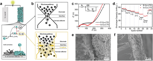
Current collectors facilitate electron transport between the electrode materials and the external circuit. Conventional current collectors, such as Cu foil for anodes and Al foil for cathodes, are widely used due to their high electrical conductivity. However, both are prone to corrosion during long-term cycling. Coating these metals with carbon film prevents corrosion and enhances electrical and charge transfer properties (Figure 9a).[62, 158, 159] Additionally, the carbon film improves the interface between the active materials and the current collector by preventing oxidation and Li-ion intermixing at the interface, while also reducing fatigue from repeated interfacial mismatches during cycling (Figure 9b).[158, 160] For example, to enhance the Li storage performance of Li4Ti5O12 (LTO) anodes, a monolayer graphene sheet was directly coated onto a Cu current collector using low-pressure CVD (LPCVD).[160] In the electrochemical impedance spectroscopy (EIS) spectra of LTO electrodes, graphene-coated Cu foil (G-Cu) exhibited a smaller solution resistance (Rs) of 2.19 Ω and charge-transfer resistance (Rct) of 91.17 Ω than those of pristine Cu foil (P-Cu) (Rs = 2.41 Ω and an Rct = 190.3 Ω) (Figure 9c). The G-Cu showed higher reversible specific capacity at high current rates (Figure 9d). The scanning electron microscope (SEM) images in Figure 9e,f further confirm that the LTO slurry layer firmly adheres to the G-Cu, while a significant gap is observed for the P-Cu, demonstrating better contact between the active material and the current collector. It was also reported that the native oxide layer on the current collector is removed during the CVD growth process of graphene and the adhesion of the LTO active layer to G-Cu is increased due to the hydrophobic nature of the graphene layer.[161]
Even in anode-free batteries (Figure 10a), an emerging battery architecture that eliminates active anode materials by pairing a fully pre-intercalated cathode with a bare anode current collector, the importance of graphene coating cannot be overstated.[162] This design has the benefits of increased energy density, simple structure, and reduced costs. However, the primary challenges in the anode-free battery are the uncontrolled deposition of metal on the current collector during cycles, leading to the formation of dendrite and unstable SEI layer, which are the main reasons for capacity loss and poor cycling stability.[163] Multilayer graphene film has been applied to a Cu current collector for anode-free LMBs.[164] The graphene film stabilizes the electrode interface by uniformly distributing current through its delocalized electrons, effectively suppressing the formation of Li dendrite (Figure 10b). The graphene-coated current collector delivered higher discharge capacities during the initial cycles of the full cell: After 100 round-trip cycles, the graphene-coated current collector retained 61% of its initial capacity, which is 16% higher than that of bare Cu (Figure 10c).
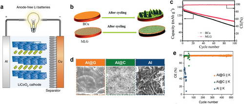
The graphene was applied by directly growing it on an Al current collector by roll-to-roll PECVD for an anode-free K-metal battery.[165] The graphene-coated Al (Al@G) showed a high average adhesion strength of 10.52 N m−1, higher than that of a carbon-coated Al (1.72 N m−1, Al@C, coated with super P carbon), and a large surface energy of 66.6 mJ m−2, three times higher than that of bare Al, which is due to highly potassiophilic nature of Al@G. The Al@G electrode led to uniform growth of K-metal (Figure 10d), resulting in highly reversible plating/stripping cycling and a high average Coulomb efficiency (Figure 10e). The ultrathin graphene layer reduces the K inventory loss, while strong adhesion to the Al substrate prevents peeling. Furthermore, the defect-rich graphene grown by PECVD enhances surface energy for smooth K plating.
The carbon film improves battery current collectors by preventing corrosion, reducing intermixing, and enhancing electrode contact, which lowers internal resistance. Its delocalized electrons stabilize the interface, and strong adhesion enables use in anode-free designs. However, key factors like thickness, graphitization, and defect density of the carbon film should be optimized further for enhanced battery performance.
4 Application of Carbon Films in Advanced Batteries
Advanced battery systems, such as LMBs, Li-S batteries, ASSBs, and Li-O2 batteries, have the potential to surpass the performance of LIBs, offering increased safety and higher energy density. However, these battery systems are facing significant challenges that hinder their commercialization, including dendritic deposition of Li ions, poor interfacial contact, and the dissolution of active materials. Carbon films have been proposed as a solution to these issues by building macroscopic carbon structures, achieving conformal coatings, or providing required properties through doping and defect control. In the following sections, we explore the application of carbon films in advanced battery systems, offering a comprehensive understanding of how carbon films address key challenges.
4.1 Lithium Metal Battery
In LMBs, Li has a high theoretical specific capacity of 3860 mAh g−1 and the lowest electrochemical potential, making it an ideal anode material for high-energy batteries.[135] However, the commercialization of LMB has been hindered by fatal obstacles, primarily the formation of Li dendrite (Figure 11a).[166] The Li dendrite can penetrate the separator, causing short circuits that may lead to thermal runaway and even explosions. The increased surface area of Li metal at dendrite sites aggravates adverse reactions, significantly reducing Coulomb efficiency. Additionally, electrochemically inert dead Li from dendrites further lowers Coulomb efficiency and increases polarization due to the extended diffusion pathway. Since dendrite growth is mainly induced by the inhomogeneous distribution of Li ions, the Li dendrite issue can be mitigated by forming a lithiophilic anode surface. Especially, graphene is an ideal host material for Li metal anodes due to its hexagonal structure, which closely matches the Li atom arrangement and promotes uniform Li deposition.[135] The large surface area of graphene also helps to distribute local current density, reducing the risk of dendrite formation and enhancing the safety and efficiency of LMBs.[167-170]
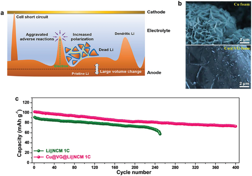
To solve this dendrite issue, graphene nanowalls were grown on Cu foams by PECVD.[171] Vertically grown graphene homogenized the electric-field distribution due to high conductivity and large reaction interface and induced a uniform Li deposition due to a highly lithiophilic surface. After depositing Li on electrodes, the Cu foam with vertical graphene exhibited dendrite-free Li plating, in contrast to the scattered Li dendrites observed on the plain Cu foam (Figure 11b). As a result, uniform deposition of Li on Cu foam with vertical graphene leads to high capacity retention (Figure 11c).
Many studies have utilized morphologies with high specific surface areas, such as vertically aligned carbon walls and foams, as a key factor in reducing local current density and promoting uniform Li-ion flux.[167-169, 171] However, high specific surface area also increases electrolyte consumption due to the formation of a thicker SEI layer. Therefore, optimizing the specific surface area of carbon-based morphologies is essential for improved performance.
4.2 Lithium-Sulfur Battery
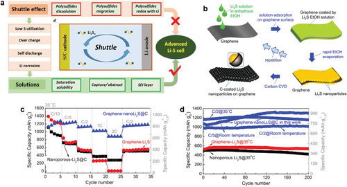
The Li-S battery with S8 as a cathode material theoretically delivers a high capacity of 1675 mAh g−1 and energy density of 2600 Wh kg−1 with an average discharge voltage of 2.2V versus Li/Li+, which are five times larger than those of commercial LIBs.[172, 173] However, this system suffers from the shuttling of soluble polysulfides, an intermediate product of the conversion reaction from S8 to Li2S, or from Li2S to S8, between cathode and anode electrodes (Figure 12a).[174] Besides, poor electrical conductivity and large volume change of the S8 cathode are huge limitations to overcome.[18, 175] Safety hazard associated with metallic Li anode is also a serious issue to be addressed.[176] To stabilize Li-S battery operation, conductive 3D frameworks loaded with sulfur as a cathode material have been recently studied using CVD.[19, 172, 177-181] These macroscopic structures simultaneously offer fast electron transport and the ability to trap undesirably dissolved polysulfide species. Moreover, an artificial interlayer made of carbon can not only inhibit the shuttling of soluble polysulfide species but also suppress the dendritic growth of Li by acting as a physical barrier or by the delocalization of charge carriers.[182] Recently, Li2S as a cathode material for Li-S batteries has been explored instead of S8, which shares the same chemical reaction during the charging and discharging process.[175, 183, 184] Despite of lower theoretical capacity (1166 mAh g−1) compared to that of S8, Li2S offers several advantages over S8.[185] Since the Li is already incorporated in the cathode, there is more flexibility in selecting the anode material.[186-189] For example, graphite or Si anode can be selected over metallic Li anode, which can eliminate the safety issues associated with Li anode. Additionally, Li2S has a higher melting point (938 °C), providing some benefits in modification steps, such as enabling high-temperature CVD processes.[190] Especially, the graphene-nanoLi2S@C nanocomposite cathode was fabricated via repeated coating processes of Li2S solution and subsequent carbon coating of Li2S nanoparticles by CVD process at 500 °C with C2H2 gas (Figure 12b).[191] The graphene-nanoLi2S@C nanocomposite outperformed the graphene-nanoLi2S nanocomposite with no protective carbon shell at high C-rates (Figure 12c), indicating the importance of carbon shell for fast reaction kinetics. The enhanced cycle stability of graphene-nanoLi2S@C nanocomposite was also confirmed by cycle tests at various C-rates and temperatures (Figure 12d). Even after 200 cycles, no significant decrease in discharge capacity was observed, which is attributed to the suppression of the shuttling effect. Moreover, reduced active material loss during large volume expansion and the formation of a smooth polymer-like CEI layer also affected the prolonged cycle life, thanks to crack-free carbon shells.
4.3 All-Solid-State Battery
ASSBs utilize a solid electrolyte that eliminates the risk of leakage and flammability, enabling to application of high-energy-density materials, like Li metal anodes (Figure 13a).[192] However, the solid-solid interface between the solid electrolyte and electrode materials is a critical issue in ASSBs, as poor interfacial contact and high resistance impede their performance. Recently, it has been reported that carbon coating can improve this interface thanks to high electrical conductivity, mechanical strength, chemical stability, and flexibility.[192] For instance, when Si nanoparticles were used in ASSBs with a solid polymer electrolyte, the swelling of Si during lithiation/delithiation caused amorphization of the nanoparticles, disrupting the anode/solid polymer electrolyte interface (Figure 13b). In contrast, Si nanoparticles coated with vertically grown graphene (Si@VG) via CVD enhanced electrical connectivity between the electrode and the solid polymer electrolyte. The vertically grown graphene, firmly attached to the Si surface, effectively accommodated the volume expansion of Si, preserving interfacial contact.[193] The EIS measurements revealed a lower SEI resistance (RSEI) of 18 Ω for the Si@VG anode, compared to 54 Ω for the Si anode (Figure 13c). The Si@VG anode also exhibited a Rct of 16 Ω, smaller than 34 Ω for the Si anode.
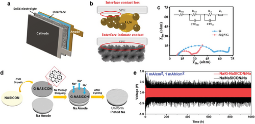
The graphene layer grown on a NASICON (Na3Zr2Si2PO12) pellet also reduced the interfacial resistance in the solid-state Na metal battery, effectively minimizing uncontrolled dendrite-like Na after repeated stripping/plating cycles (Figure 13d).[194] As a result, the graphene interlayer reduced the large NASICON/Na interfacial resistance by 10 fold from 524 to 46 Ω cm2. The graphene-coated NASICON maintains consistently stable cycling behavior at a higher current density of 1 mA cm−2 (Figure 13e).
4.4 Lithium-Oxygen Battery
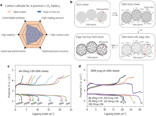
Li-O2 batteries have attracted considerable attention due to their extremely high theoretical energy density of 3500 Wh kg−1.[195] However, limited active sites for the formation and decomposition of insulating discharge product (Li2O2) and sluggish kinetics of this reaction are major bottlenecks in the Li-O2 cell, which leads to a large overpotential, low capacity, and fast capacity fading.[196] Well-designed morphology of carbon films is one of the options for the cathode, owing to its large specific surface area, great electrical conductivity, and processibility. A criterion for the ideal carbon cathode is presented in Figure 14a.[197] Recently, the correlations between the properties of carbon films, such as porosity, thickness, or number of layers, and the performance of Li-O2 batteries have been studied.[198] The carbon cathode was synthesized by depositing the carbon on the Al2O3 substrate via CVD, followed by etching of the substrate and an additional annealing process (Figure 14b). The morphology and properties of carbon cathode were effectively controlled by varying three experimental parameters, which are 1) pelletization force to Al2O3 (x[N]) to control the porosity and thickness, 2) the amount of Al2O3 powder (γ[mg]) to control the thickness, and 3) duration of CVD (z[h]) to control the number of carbon layers. This study revealed that the areal and specific capacity would increase when the pelletization force is decreased due to increased total porosity (Figure 14c). Moreover, the areal capacity slightly increased when the duration of CVD was short, indicating that the low number of carbon layers is beneficial in realizing higher areal capacity (Figure 14d). Despite recent progress, further investigation is needed into microscopic structural factors, such as defects, dopants, and grain size of the carbon layer, which significantly impact the performance of Li-O2 cells. Additionally, optimizing the CVD process for better control of these properties is essential.
5 Conclusion and Perspectives
In conclusion, this review highlights the significant role of carbon films in enhancing the electrochemical performance of various secondary batteries. Throughout the paper, we have detailed the diverse advantages of CVD-grown carbon films and their applications in battery components and advanced battery systems. CVD technology allows for carbon coating on irregularly shaped powdery materials, the synthesis of unique macroscopic structures, and precise control over microscopic properties of carbon by adjusting experimental parameters, which was not achievable through conventional wet-chemical or solid-state methods. These applications have successfully addressed some major issues in secondary battery systems.
Despite numerous efforts to utilize carbon films to overcome the challenges of secondary battery systems, the number of studies addressing theoretical or fundamental aspects remains limited. Future research should focus on gaining a deeper understanding of how the properties of carbon films can influence their performance in battery applications. Key parameters such as film thickness, defect density, porosity, degree of graphitization, grain size, or type of dopants can significantly affect the electrochemical performance of secondary batteries. However, these relationships remain underexplored, and the lack of comprehensive studies hinders the ability to fully optimize carbon films for diverse energy storage systems. It is essential to fully understand these correlations for exploring ideal structures or properties of carbon films for battery applications.
Furthermore, controlling the microscopic properties of carbon films through the CVD process requires further study, which can be achieved by fine-tuning parameters such as deposition time, temperature, and gas precursors. A more precise understanding of these mechanisms is essential to achieve ideal macroscopic morphologies and required properties of carbon films. Future research aiming at establishing clear correlations between these properties and battery performance and exploring the synthetic parameters to realize the optimized design of carbon films will pave the road for suggesting more effective and powerful solutions in next-generation energy storage technologies.
In the context of the practical application of CVD-grown carbon films for secondary batteries, several challenges remain to be addressed. One significant limitation lies in achieving carbon layers with high crystallinity on thermally unstable substrates, such as NCM. Due to the insufficient thermal energy required for the regular arrangement of carbon atoms, only amorphous carbon layers can be deposited at relatively low temperatures, even with the assistance of plasma to dissociate CH4 gas. Moreover, achieving a uniform carbon coating on powdery materials presents additional challenges. The limited delivery of carbon precursors to the gap between densely packed powders or to the bottom regions of the crucible used for sample loading hinders the formation of a uniform carbon layer. While rotary CVD systems offer a potential solution, they are accompanied by disadvantages such as high initial installation and maintenance costs. Future research focusing on innovative approaches to achieve high-quality carbon films at relatively low temperatures, as well as the development of advanced CVD systems to address uniformity issues, will provide valuable insights into enabling the practical application of CVD-grown carbon films in secondary batteries.
Acknowledgements
J.K. and Y.-W.C. contributed equally to this work. This work was supported by the Basic Science Research Program (NRF-2021R1A2C3014316) through the National Research Foundation of Korea (NRF) funded by the Ministry of Science, ICT & Future Planning, and Creative-Pioneering Researchers Program through Seoul National University (SNU). G.H.L. acknowledges the support from the Research Institute of Advanced Materials (RIAM), Institute of Engineering Research (IER), Institute of Applied Physics (IAP), and Inter-University Semiconductor Research Center (ISRC) at the Seoul National University.
Conflict of Interest
The authors declare no conflict of interest.
Biographies

Jiwoo Kim is a postdoctoral researcher at Seoul National University under the supervision of Prof. Gwan-Hyoung Lee. He received his Ph.D. in Materials Science and Engineering from Seoul National University in 2025. His research focuses on the synthesis of carbon films and the development of advanced fabrication techniques based on graphene.

Young-Wook Cho is a Ph.D. student at Seoul National University under the supervision of Prof. Gwan-Hyoung Lee and also conducting his research at Korea Electronics Technology Institute (KETI). His research focuses on the interface modification of cathode materials for Li-ion battery applications.

Sang-Gil Woo is a Senior Researcher at the Korea Electronics Technology Institute (KETI) in the Republic of Korea. He received a Ph.D. in Materials Science and Engineering from Seoul National University in 2006. Then, he worked for Samsung SDI until December 2011. Currently, his research focuses on advanced battery systems, such as the manufacturing of dry electrodes, Li-S batteries (Li-S), and Anode-free systems.

Je-Nam Lee is a Principal Researcher at the Korea Electronics Technology Institute (KETI) in the Republic of Korea. He received a Ph.D. in Chemical and Biomolecular Engineering from Korea Advanced Institute of Science and Technology (KAIST) in 2013. Then, he worked for Samsung Advanced Institute of Technology (SAIT) until May 2016 before. Currently, his research focuses on the components and system configurations of the Li metal battery (LMBs), Li-S battery (Li-S), and Li-ion battery applications.

Gwan-Hyoung Lee is a professor at Seoul National University. He received a Ph.D. in Materials Science and Engineering from Seoul National University in 2006. Then, he worked for Samsung Electronics. In 2010, he joined Columbia University as a postdoctoral researcher. After five years at Yonsei University, he is now with Seoul National University since 2019. His research activities include the investigations of electrical, mechanical, and optical properties of 2D materials as well as 2D-material-based heterostructure devices for electrical and optoelectronic applications.


