3D Printable Magnetic Soft Actuators–Ink Formulation, Rheological Characterization, and Hydrogel Actuator Prototypes
Abstract
Magnetic inks are presented for direct ink writing (DIW), a 3D printing technique, yielding magnetic hydrogel actuators. To obtain the shear-thinning and thixotropic behavior needed for DIW, the rheology modifier laponite is used. This additive ensures suitable rheological properties and dispersion of the magnetic iron oxide nanoparticles used. The base formulation of the ink consists of acrylamide as monomer, N,N’-methylenbisacrylamide as cross-linker, and ammonium persulphate as thermal initiator. The concentration of laponite varies from 1.5 to 6.9 mass%, and the effect on the ink viscosity, shear-thinning properties, and printability of the system is investigated. Starting at a concentration of 3.8 mass% laponite, the iron oxide nanoparticles are sufficiently stabilized to prevent sedimentation. The ink viscosity can be tuned over almost two orders of magnitude, with an optimum printability at 4.6 mass% laponite. The printed hydrogel precursors are cross-linked thermally at 50 °C. Thus, magneto-responsive prototypes for soft robotics applications are obtained. The advantages of the system are that a low mass percentage of rheology modifier is needed, that the number of polymeric components is reduced, and that the obtained hydrogels are mechanically stable. Laponite-containing ink is easy to handle and can therefore also be used in non-specialist laboratories.
1 Introduction
3D printing of polymer hydrogels has received increasing attention in the past decade, especially due to the unique design freedom of 3D printed objects.[1-5] Combining this innovative processing technique with the structural versatility of hydrogels provides an avenue toward sophisticated applications like programmable soft actuators or stimulus-responsive biomedical devices.[1, 6] In this context, we are particularly interested in magnetically actuated hydrogels.[6] These are typically based on natural polymers and have prospective applications as artificial muscles, microgrippers, and microvalves, in vivo maneuverable microrobots, and other soft robotics devices.[6] These devices typically require some degree of structural anisotropy, which is difficult to achieve with conventional processing techniques but readily accessible by 3D printing.[1, 7, 8] The aim of this work was to obtain magnetic polymer hydrogels made from synthetic polymers that could be 3D printed from a gel-like ink. These would have higher long-term chemical stability than the typical carbohydrate and peptide-based systems of the bioprinting community, which are designed for (bio)degradability and biocompatibility,[9] and thus are often not applicable for more technical applications where microbial or hydrolytic degradation is a concern.
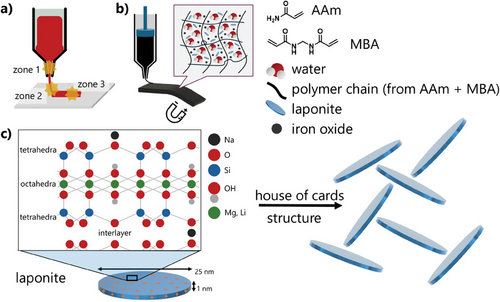
3D printing of hydrogels is not yet as advanced as 3D printing of thermoplasts. Nevertheless, suitable techniques exist, including direct ink writing (DIW). DIW is an extrusion-based process in which shear-thinning gel-like inks containing either monomers or reactive functional polymers are used as precursors. These are turned into physically or covalently cross-linked hydrogels by post-printing treatment, which is typically a thermally or UV-induced cross-linking process.[1, 9] For DIW inks, the crucial point is to tune the ink viscosity so that it fits to each of the stages of the printing process, as illustrated in Figure 1a. While exiting the nozzle (zone 1), low ink viscosity is required to enable extrusion. When deposited on the print bed (zone 2), an instant increase in ink viscosity is needed for the shape fidelity of the printed object. Finally, when several layers are deposited on top of each other (zone 3), sufficient mechanical stability of the ink through high viscosity and high yield stress ensures that the structure is self-supporting until it is cross-linked.[1, 10] Thus, inks for DIW should not only have a suitably high viscosity at rest, but must also be shear-thinning and thixotropic. Shear-thinning refers to the ability of the ink to adopt a low viscosity when exposed to the shear forces and shear rate inside the nozzle; thixotropy describes the rate of recovery of the high viscosity state. These properties are typically obtained by the addition of rheology modifiers. The resolution of DIW is limited by the rheological properties of the ink and the minimal tip size of the printing syringe of a given DIW system. Both determine the minimal volume of fluid that can be deposited continuously, which is important for the printing resolution. For the given system, the nozzle diameter was 0.58 mm, which at the set printing parameters gave a shear rate of ≈32 s−1 (see Supporting Information, Calculation 1). While having a lower resolution, DIW has the advantage over vat-based techniques (e.g., two-photon stereolithography, vat photopolymerization) in that it does not require large amounts of fluid to fill an entire vat, but only the volume used to print the actual object is required. Additionally, multiple ink types with different compositions can be used in DIW simultaneously, giving access to gradient materials.
Rheology modifiers for shear-thinning and thixotropic properties form reversibly bonded supramolecular interactions that can likewise be reversibly broken by shear forces. In the context of DIW, a commonly used polymeric rheology modifier is the amphiphilic triblock copolymer poly(ethylene oxide-block-propylene oxide-block-ethylene oxide) (Pluronic F127, with an average molar mass of roughly 12600 g mol−1, i.e., ≈100 repeat units in each polyethylenoxide block, and ≈55 in the central polypropylenoxide block), which undergoes a temperature-induced sol-gel transition – it forms micelles at room temperature, and micellar aggregates at higher temperatures.[11, 12] It is sometimes used as a sacrificial rheology modifier and removed after printing by solvent extraction.[13] In recent work, we have shown that this rheology modifier can be used to formulate inks for DIW of magnetic hydrogel actuators.[14] These inks had a predominantly liquid character inside the nozzle at room temperature but became a gel-like solid when deposited on the print bed which was held at 50 °C. The object shape was then fixed by UV-induced polymerization of acrylamide and N,N’-methylenebisamine (which formed the base formulation of the ink), and additional wet-chemical cross-linking to immobilize chitosan (which acted as a dispersing agent for the iron oxide nanoparticles).[14] The disadvantage of this system was that the obtained structures were quite fragile, and as much as 20–30 mass% Pluronic F127 were needed to obtain the desired shear-thinning properties. Having such a high percentage of a polymeric rheology modifier not only limits the range in which the mechanical properties of the target system can be tuned. Is it also undesirable for polymer hydrogels to have multiple polymer components because different polymers demix unless they are structurally similar, i.e., when they have a low Flory–Huggins interaction parameter. Demixing leads to phase separation, which negatively affects the structural homogeneity and distribution of hydrogel components on the microscale and thereby reduces the mechanical strength and/or toughness of the material.
Only a few other systems that yield magnetically responsive, 3D-printed hydrogels have been reported. In one case, an ink for DIW made from methacryloyl-functionalized gelatin in combination with iron oxide nanoparticles was used. Here, gelatin also acted as the rheology modifier, and post-printing UV treatment yielded macroscopic hydrogel swimmers.[15] In a similar system, two-photon polymerization was used for UV cross-linking of the functionalized gelatin to obtain microswimmers.[16] For other DIW printed, magnetically actuated hydrogel materials, the rheology modifiers used were polyelectrolytes like colloidal polyacrylic acid (carbomer, used at 0.5 mass%),[17] or carbohydrate derivatives like alginate methyl cellulose.[8, 18] These rheology modifiers are all polymers, which for the above-described reasons were to be avoided. In other contexts than magnetic actuation, nanoclays like laponite were used as rheology modifiers for 3D-printed hydrogels.[9, 19, 20] Laponite is a phyllosilicate that forms highly viscous superstructures in solution. Due to its biocompatibility and because it degrades into non-toxic components, it is widely used, e.g., in cosmetics, paints, and biomedical applications including cell culture systems.[20, 21] Laponites are nanoplatelets with a diameter of ≈20–25 nm and a thickness of 1 to 2 nm.[21] They have a negative zeta-potential of ≈−40 mV,[22] with negative charges on their faces and positively charged edges. Their superstructure in solutions with laponite concentrations up to a few percent, according to one group of publications, is a so-called house of cards superstructure (Figure 1c).[9, 19, 23, 24] It is assumed that this structure forms by attractive interactions between the edges and the faces, an assumption based on, e.g., rheological experiments where a sol-attractive gel transition was found.[24] However, in other works, e.g., based on x-ray and neutron scattering experiments, there is evidence that the laponite superstructure can be dominated by repulsive interactions between the platelets.[20, 21, 23] As such, laponite-containing fluids have been interpreted not as fractal networks with a house-of-card structure and stabilized by attractive interactions, but as soft glasses whose structure is based on repulsive interactions.[21, 25] Care must be taken when analyzing, comparing, and interpreting these results. First, there are different types of laponite with various grades of heavy metal impurities, and second, it was shown that the solution pH, salt addition, addition of charged polymers, and changes of solvent affect the exact superstructure obtained,[20, 21, 23] so that it may differ depending on the exact system under investigation. Independent of the exact nature of the laponite superstructure, there is a consensus that formulations containing a few percent of laponite in an aqueous solution are shear-thinning,[22, 26] The reason for this is that the laponite superstructure easily breaks down under shear and re-forms fast once the shear forces are removed.
We here present DIW inks based on acrylamide (AAm) and iron oxide nanoparticles that yield magnetic soft actuators (Figure 1b). Acrylamid was chosen as a monomer because the biocompatibility of polyacrylamide-based hydrogels is well-documented.[27] Laponite was used as a rheology modifier but has an additional function as a dispersing agent for the iron oxide nanoparticles. Thus, in our ink formulation, there are no polymeric components, and in the target hydrogel material, the only polymeric component is the actual hydrogel scaffold. Consequently, there is no thermodynamically driven phase separation of the polymeric components within the ink or the hydrogel itself, and these inks should yield a homogeneous distribution of all components on the microscale within the hydrogel actuator. Additionally, since the rheological properties of the ink are dominated by the laponite content, this recipe can be easily transferred to other monomer systems, so that it provides access to a whole family of magnetic hydrogel systems.
The magnetically responsive hydrogels should be obtained by thermal cross-linking during post-printing treatment (Figure 1b). A low volume percentage of the rheology modifier was aimed at. To optimize the ink viscosity and printing performance, the laponite concentration was varied, and the effect was studied by rheological measurements. Further, the effect of temperature on the viscoelastic properties of the inks was investigated. With optimized inks, hydrogel precursors were printed and cross-linked into magneto-responsive model actuators by thermal polymerization. Their actuation was demonstrated by permanent and electromagnets.
2 Results and Discussion
2.1 Ink Formulation and Determination of Gel Content and Swelling Ratio
The base formulation used for optimizing the ink properties consisted of 5.0 g deionized water, 1.50 g (21.1 mmol) of the monomer AAm (30 mass% relative to water), 0.24 mmol of the cross-linker N,N’-methylenebisamide (MBA, 1 mol% of the monomer amount), and ammonium persulfate (APS), a thermal initiator for the free radical polymerization of the target hydrogel. The magnetic components were iron(II, III) oxide nanoparticles (NP). The NP amount was typically 0.4 mass%, and the laponite (L) concentration was varied from 1.5 to 6.9 mass%. The sample naming indicates the laponite and iron oxide mass percentage. A sample with 3.1 mass% L and 0.4 mass% NP was thus termed L3.1NP0.4.
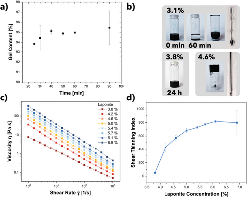
For optimal shape fidelity and resolution of 3D printed hydrogels, it is important that DIW inks used do not flow after deposition onto the print bed, and that they polymerize near-quantitatively during post-printing treatment. In the presented work, the flow was prevented by laponite addition, and the printed ink structures were transformed into hydrogels by thermally induced free radical polymerization (FRP). As is well known, the reaction rate of FRP strongly depends on the monomer and initiator concentration. In the context of actuators, a suitable amount of cross-linker is needed to obtain a sufficiently stiff and tough material. To confirm that the chosen ink base formulation polymerizes well and cross-links to a sufficient extent (so that the actuators obtained can be handled without breaking) and within a suitable reaction time, its gel content was determined prior to optimizing its rheological properties. For that purpose, rectangular hydrogel sheets of 2 by 2 cm were fabricated by molding using an ink formulation with the above specified amounts of AAm, MBA, and APS, as well as 4.6 mass% L and 1.5 mass% NP (= L4.6NP1.5). Each hydrogel sheet was cross-linked at 50 °C for a determined timespan. The mass of the dry gel before and after extracting the unpolymerized monomer was determined gravimetrically to calculate the gel content (). Mechanically stable hydrogels were already obtained after 20 min of thermal treatment. In the plot of the gel content versus the cross-linking time, a plateau was reached after 40 min (Figure 2a). In the light of these results, the standard cross-linking time was set to 40 min, where a gel content of 95% was observed. The swelling ratio was determined by measuring the dry mass and the wet mass of the polymer hydrogels (). As an average over three samples, this gave 397.0 ± 6.7%.
2.2 Effect of the Laponite Concentration on the Iron Oxide Dispersion and Ink Viscosity
Laponite served a dual purpose in this work. First, varying the laponite concentration allowed to tune the rheological properties of the system. Second, the interaction of the NPs with laponite enabled their lasting dispersion within the ink, where they would otherwise precipitate within minutes. To investigate the effect of laponite concentration on the ink viscosity, it was varied from 1.5 to 6.9 mass% (relative to the overall mass of the base formulation consisting of water, AAm, and MBA). Up to 3.1 mass% laponite, the inks had a low viscosity and did not stabilize the NPs sufficiently. Lines printed using L3.1NP0.4 ink immediately flowed (Figure 2b). At a laponite concentration of 3.8 mass%, the ink viscosity visibly increased, and the nanoparticles did not sediment within 24 h (Figure 2b). At a laponite concentration of 4.6 mass%, the viscosity was sufficiently high to prevent flow when the sample vial was turned upside down, and lines printed using an L4.6NP0.4 ink retained their shape (Figure 2b). At 5.4 mass%, the ink viscosity was too high for a steady, continuous flow during printing, so the maximal laponite concentration for printing should be kept below that value.
The rheological behavior of inks with different laponite concentrations was quantified by rheology using a steady-state flow shear rate sweep test. The shear rate was increased step-wise from 1 to 103 s−1 (waiting for 30 s to equilibrate the system after each measurement) and the resulting viscosity at constant rotation was recorded (Figure 2c). In a log-log plot of viscosity versus shear rate, all samples with 3.8 to 6.9 mass% laponite had a linear reduction of viscosity with shear rate, thus confirming shear-thinning behavior. For example, when the data for L4.6NP0.4 was fitted using the Ostwald de Waele relationship, , with and as fitting parameters, which describe the behavior of a fluid, k = 59.26 ± 2.29 and a negative flow index n = − 0.92 ± 0.01 was obtained, which in this power-law confirms shear thinning behavior. A shear stress versus shear rate plot of L4.6NP04 also confirmed typical shear thinning behavior (Figure S1, Supporting Information). The curve could be fitted with the Herschel–Bulkley model, , where is the shear stress, τ0 the initial shear stress, and k and n are fitting parameters. The flow index n = 0.54 ± 0.01, which is smaller than one, indicates shear thinning. The linear fit of the Bingham model , where nB is the fitting parameter, does not follow the data.
Within the measured shear rate range, the viscosity of the L3.8NP0.4 ink was almost two orders of magnitude lower than that of the L6.9NP0.4 ink (at rest: 7.8 Pa⋅s vs 334.8 Pa⋅s). The viscosity at rest of L3.8NP0.4, 7.8 Pa⋅s, can be considered as the approximate minimum viscosity for shape fidelity when printing this system. The viscosity at rest of L5.5NP0.4 was 131.2 Pa⋅s, which should be considered as the approximate maximum viscosity value to avoid printing problems such as unsteady flow. Note that these viscosity limits are only applicable to the DIW system used in this work and need to be evaluated for different setups separately. To determine the relative viscosity decrease of the inks under shear, a shear thinning index was calculated by taking the ratio between the viscosity at 1 s−1 and the viscosity at 103 s−1 (). Figure 2d shows a plot of the shear thinning index versus the laponite concentration. That index increased with increasing laponite concentration and leveled off into a plateau at 5.7% laponite, i.e., this amount was sufficient to build a percolating superstructure through the ink volume. A laponite amount of 4.6% qualitatively gave the best shape fidelity and printing performance, indicating that there is no need to reach the maximum possible shear thinning index for the formulation to obtain a printable ink.
2.3 Temperature, Shear Rate, and Time Dependency of the Mechanical Properties of the Inks
While the viscosity of the inks had a clear shear-rate dependency at constant rotation, frequency sweeps from 1 to 10 Hz under oscillatory conditions had only slight effects on the magnitude of the shear moduli G′ and G′′ (measured at 0.1% strain, Figure 3a). Only for the highest laponite concentration (5.7 mass%), an increase of G′′ in the measurement range (from 1⋅10−1 to 2.5⋅101 Hz) was observed. For 4.2 and 4.6 mass%, the value of G′′ remained almost constant (at ≈8 Pa) over the entire measurement range. G′ showed an increase for all concentrations, which leveled off into a plateau afterward. Importantly, in the entire measurement range, G′ was larger than G′′, indicating that the ink at rest behaved more like a viscoelastic solid than like a liquid. Temperature-dependent oscillatory measurements from 22 to 60 °C at a shear rate of 1 Hz using L4.6NP0.4 also showed that G′ was larger than G′′ over the entire shear rate range (Figure 3b). This is substantially different from the temperature dependency under dynamic conditions of the previously studied F127-based inks.[14] Starting at a temperature of 27 °C and up to 50 °C, G′of these ink increased by almost two orders of magnitude compared to room temperature. Further, these inks had a cross-over from G′ < G′′ to G′ > G′′ at 27 °C due to the well-known aggregation of the F127 micelles. In these systems, the cross-over behavior was crucial to prevent ink flow, and the shapes printed from these inks only showed shape fidelity at higher temperatures.[14] For the here investigated system, G′ was larger than G′′ already at room temperature. Also, the ratio did not change in the temperature range from 27 to 60 °C, so that the temperature of the print bed can be kept at room temperature during printing. Another advantage of the presented system is that already at a laponite concentration of 4.2 mass%, the ink viscosity was as high as that of the F127 system at 30 mass% F127, i.e., a much smaller mass and volume fraction of rheology modifier was needed.
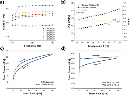
The time dependency of the mechanical response, i.e., the thixotropic properties of these laponite-based inks was evaluated for L3.8NP0.4 and L6.7NP0.4 by ramping up the shear rate from 0.1 to 100 s−1 and back while measuring the shear stress τ (Figure 3c,d). Further data for other laponite concentrations can be found in the supporting information, in Figure S2 (Supporting Information). The shear rate versus shear stress τ curves (Figure 3c,d) show a hysteresis, which is typical for thixotropic behavior. By calculating the difference in the area between the up-sweep and the down-sweep from the τ versus plot, the so-called thixotropy index was determined.[28] For the here investigated samples, the thixotropy index ranged between 301 and 3724 Pa⋅s−1 (Table S1, Supporting Information). Thus, the thixotropy index increased with increasing laponite concentration, indicating that the samples with more laponite suffered a larger degradation of the superstructure by shear. Overall, the structure recovery rate of these samples (quantified by the closeness of the up-sweep and the down-sweep curve) was sufficiently fast to prevent ink flow and ensure shape fidelity.
Both the area of these hysteresis curves and the value of the thixotropy index strongly depend on the experimental parameters and therefore are not used as quantitative materials properties.[14-16] However, these parameters were useful to compare the thixotropic properties within this series of inks and can be used as a benchmark for future work using the same experimental conditions.
2.4 Prototype Printing by DIW, Post-Printing Treatment, and Prototype Actuation
As the above-described experiments indicated, inks with a laponite content of ≈4.6 mass% had optimal printing performance and shape fidelity. Using this ink formulation, hydrogel precursors consisting of five layers were obtained by DIW. After printing, the print bed was heated to 50 °C to induce thermal cross-linking. The thus cured hydrogel prototypes could be removed from the print bed without damage. There was no need for further post-printing treatment. This is a significant advantage over the previously reported magnetic inks containing F127, which were mechanically sensitive and required further treatment with sulfate ions to cross-link the comprised chitosan, a third polymer component of that system besides F127 and polyacrylamide.[14] The hydrogels printed from precursor ink L4.6NP2.3 are shown in Figure S3 (Supporting Information).
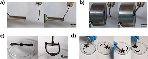
Simple magnetic actuation was shown by placing a rectangular hydrogel strip (size: 12.5 mm x 40 mm x 1 mm) into the magnetic field of a NdFeB (B = 1.29 T) permanent magnet (Figure 4a). The strip bent until it touched the magnet. The reversibility of the effect was shown using an electromagnet (120 N, 7 W, Figure 4b). Another prototype had a propeller-like shape (length: 60 mm, width: 10 mm, thickness: 2 mm, Figure 4c). When the permanent magnet approached the propeller, a gripping behavior was obtained. Flower-like shapes (diameter: 26 mm, thickness: 2 mm) floating in water followed a moving permanent magnet (Figure 4d; Video S1, Supporting Information). The type of magnetic actuation shown in Figures 4a,b can be useful as a valve or dynamic fluid doser in soft fluidic systems. Gripping actuation as shown in Figure 4c could find applications in soft robotics.
2.5 Morphological and Mechanical Characterization of the Hydrogels
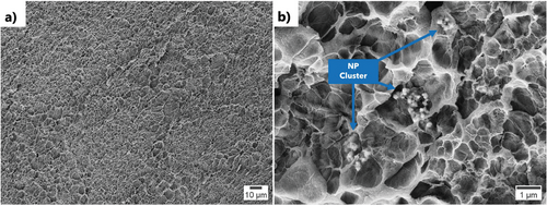
A cross-section of a hydrogel actuator printed using L4.6NP0.8 was prepared by freeze drying and freeze-fracture, sputtered with gold, and imaged by scanning electron microscopy (SEM) at 5 kV using the secondary electron detector. At 500 x magnification, a porous structure with a relatively uniform pore distribution was found (Figure 5a). The pore size was larger than in the previous study where 30 mass% F127 was used as a rheology modifier,[14] i.e., this laponite-based ink yielded less dense hydrogels. In a further image taken at 10 000 x magnification, clusters of the magnetic nanoparticles were observed (Figure 5b). The particles had a diameter of roughly 100 nm and formed clusters that were ≈1 µm in diameter. These clusters have the same size as those imaged by optical microscopy in the DIW inks of the F127 system.[14] While in that hydrogel material, the clusters were embedded within the denser hydrogel structure, in the laponite system the clusters could be clearly observed. They were also identified by electron dispersive x-ray spectroscopy (Figure S4, Supporting Information). Further, SEM studies indicated that an increase in the iron oxide nanoparticle concentration increased the number of clusters, but not the cluster size, i.e., the clusters form before the ink is mixed.
For mechanical testing, dog-bone shape hydrogel samples (Figure S5a, Supporting Information) were DIW-printed from L4.6NP2.3, thermally cross-linked, and subject to a uniaxial tensile test. This gave a median elastic modulus of 22 ± 5 kPa, with a maximum tensile stress of 0.12 N mm−2 and a yield strain of 5.5% (Figure S5b, Supporting Information). In comparison, a hydrogel obtained from the base formulation without laponite and iron oxide nanoparticles obtained by mold casting had an elastic modulus of 22 ± 7 kPa, a maximum tensile stress of 0.10 N mm−2 and a yield strain of 4.0%. Thus, the mechanical properties of the hydrogels were hardly affected by the presence of the inorganic fillers at the mass percentages used, particularly in light of the large experimental errors in these mechanical tests, which reflect the difficulty of mechanically clamping hydrogel samples for tensile tests. Note that the reference material without laponite and nanoparticles had to be mold-cast as the viscosity of its precursor solution was too low for DIW. Still, the measured mechanical properties are remarkably similar, indicating that neither the fabrication method nor laponite or iron oxide had adverse effects on these values. Literature values of the elastic modulus of polyacrylamide hydrogels range from 10 to 100 kPa,[17, 18] which is in good agreement with the here presented data.
3 Conclusion
The above results demonstrate that acrylamide-based magnetic inks containing iron oxide nanoparticles and laponite as a rheology modifier could be successfully used for DIW printing and had, in the set-up used, an optimum ink viscosity at 4.6 mass% laponite. The printed hydrogel precursors were cross-linked by thermally induced free radical polymerization. The thus obtained hydrogels could be actuated magnetically, demonstrating bending and gripping motion. As all components of the ink are biocompatible, such actuators could find applications in the biomedical field, besides technical applications such as non-rigid grippers in the field of soft robotics.
As the rheological properties of the ink formulation are dominated by the laponite content, the here presented recipe can be easily transferred to other monomers and functional nanoparticles, so that a whole family of functional hydrogels is accessible based on this work. Also, as only less than 5 mass% (and, at a density of ≈1 g cm−3, also less than 5 vol%) of laponite is needed to obtain the desired ink viscosity, the mechanical properties of the system are dominated by the elasticity of the hydrogel system and not by the rheology modifier. This is of crucial importance because it simplifies the design of DIW inks with targeted mechanical properties. Thus, in summary, the main contribution of this work to the field is that it provides a recipe for easy-to-formulate DIW inks based on the rheology modifier laponite, which gives access to magnetic hydrogel actuators and other functional hydrogels with a homogeneous microstructure.
Previously reported magnetic microactuators, such as microvalves and grippers, could be obtained at much higher resolution and with more sophisticated actuation modes.[19] For example, Li et al. designed a 3 mm big microgripper capable of gripping and releasing a microbead.[20] In these systems, the actuators were obtained by stereolithography, which intrinsically has a higher resolution than DIW and is not limited by viscosity constraints. However, it bears other disadvantages, such as the large amount of material needed to fill the bath in which any object is built, and the relative inflexibility in varying the material composition. Whether stereolithography, the related vat photopolymerization or DIW is the more useful technique to obtain magneto-responsive actuators thus depends on the desired resolution and material composition.
In future work, the here presented magnetic inks should be treated with high-power ultrasound to break the nanoparticle aggregates and thus obtain an even better distribution of magneto-responsive entities in the material. This would potentially also make them useful for 3D printers with a higher resolution than the one used in this work so that more miniaturized systems can be obtained.
4 Experimental Section
Materials
Acrylamide (≥ 99%) (AAm), N,N-methylenebis(acrylamide) (99%, MBA), 2-hydroxy-4-(2-hydroxyethoxy)-2-methylpropiophenone (98%), ammonium persulfate (98%), and iron(II, III) oxide nanopowder (particle size: 50 to 100 nm) were purchased from Sigma–Aldrich/Merck, Taufkirchen, Germany. The nanoclay Laponite RD was purchased at Kremer Pigmente, Aichstetten, Germany. All chemicals were used as received. Ultrapure (DI) water was obtained from the TKA MicroPure water purification system (JWT GmbH, Jena, Germany) and had a resistivity of 18.2 MΩ cm.
Ink Preparation
-
Base formulation. The base formulation was obtained by dissolving the monomer AAm (1500 mg) in 5 mL DI water at room temperature while stirring at 800 rpm using a magnetic stirrer. After 30 min and complete monomer dissolution, 37.5 mg of the cross-linker MBA was added, and the solution was further stirred for 30 min.
-
Laponite addition and variation of the laponite concentration. To the base formulation, different amounts of laponite as specified in Table 1 were added while stirring at 1200 rpm, so that the solution had a vortex in the middle. The powder was continuously and very slowly added into the vortex to avoid agglomeration. After adding half of the designated amount, the stirring speed was increased to 1500 rpm to maintain the vortex. The solution was stirred for a total of 60 min. Samples were named LX, where X represents the mass percentage of laponite added.
-
Variation of the iron oxide nanoparticle concentration. To investigate the effect of the iron oxide nanoparticle concentration on the solution viscosity, varying amounts of iron oxide nanoparticles as specified in Table 2 were added to the base formulation. Depending on that concentration, the samples were labeled as NPY, where Y represents the mass percentage of nanoparticles.
-
Initiator addition. Inks intended for the rheological measurements were used without the addition of the initiator. To the inks used for DIW, 37.5 mg of ammonium persulfate initiator was added just before transferring the ink into the printer. The mixture obtained was vortexed shortly, and nitrogen gas was bubbled through it for 10 min using a syringe needle.
| L0 | L1.5 | L2.3 | L3.1 | L3.8 | L4.2 | L4.6 | L5.0 | L5.4 | L5.7 | L6.1 | L6.9 | |
|---|---|---|---|---|---|---|---|---|---|---|---|---|
| DI [mL] | 5 | 5 | 5 | 5 | 5 | 5 | 5 | 5 | 5 | 5 | 5 | 5 |
| AAm [µMol/mL] | 4225 | 4225 | 4225 | 4225 | 4225 | 4225 | 4225 | 4225 | 4225 | 4225 | 4225 | 4225 |
| MBA [µMol/mL] | 49 | 49 | 49 | 49 | 49 | 49 | 49 | 49 | 49 | 49 | 49 | 49 |
| APS [µMol/mL] | 33 | 33 | 33 | 33 | 33 | 33 | 33 | 33 | 33 | 33 | 33 | 33 |
| Laponite [mg] | 0 | 100 | 150 | 200 | 250 | 275 | 300 | 325 | 350 | 375 | 400 | 450 |
| Laponite [mass%] | 0 | 1.5 | 2.3 | 3.1 | 3.8 | 4.2 | 4.6 | 5.0 | 5.4 | 5.7 | 6.1 | 6.9 |
| NP0 | NP0.2 | NP0.4 | NP0.8 | NP1.5 | NP2.3 | |
|---|---|---|---|---|---|---|
| DI [mL] | 5 | 5 | 5 | 5 | 5 | 5 |
| AAm [µMol/mL] | 4225 | 4225 | 4225 | 4225 | 4225 | 4225 |
| MBA [µMol/mL] | 49 | 49 | 49 | 49 | 49 | 49 |
| APS/UV-INI [µMol/mL] | 33 | 33 | 33 | 33 | 33 | 33 |
| NP [mg] | 0 | 12,5 | 25 | 50 | 100 | 150 |
| NP [%] | 0 | 0.2 | 0.4 | 0.8 | 1.5 | 2.3 |
Rheological Characterization
The rheological measurements were performed using a Haake Mars 40 Rheometer (Thermo Fisher Scientific, Karlsruhe, Germany) with a parallel plate setup (plate diameter of both plates 25 mm; plate gap 0.75 mm) and a Peltier temperature control system. The temperature was 20 °C. Shear rate sweep tests from 1 to 1000 s−1 at 1 Hz were performed to determine the shear-thinning profile of the inks (viscosity vs shear rate, continuous rotation). Frequency sweep tests were conducted from 0.1 to 10 Hz (storage shear modulus G′ and loss shear modulus G′′ vs frequency, oscillatory rotation) at different laponite concentrations. The temperature-dependency of the system was investigated by monitoring G′ and G′′ as a function of temperature at a constant shear rate (continuous rotation, 0.1% strain). The thixotropic behavior of the ink was investigated by continuously increasing the frequency from 0.1 Hz to 100 Hz within 100 s. After maintaining these conditions for 30 s, the shear rate was reduced back to 0 Hz within 100 s.
3D Printing
The DIW printer used was a Reg4Life (Regemat3D, Granada, Spain) with a bioink extrusion syringe print head. The software used was R4L Designer (Regemat3D, Granada, Spain). CAD models were designed with Fusion 360 (Autodesk, San Rafael, USA). The build plate temperature was 50 °C. 3 mL of the ink was transferred into a cartridge without inducing bubble formation. The distance between the nozzle and the print bed was ≈0.5 mm. It was adjusted prior to each print process. The nozzle diameter and thus the XY resolution was 0.58 mm. The overall dimensions of the printed structures were 150 mm x 160 mm unless indicated otherwise. The infill was 100%, a diagonal grid with a tilt angle of 45 ° was used. The layer height was 0.4 mm (Z resolution); the extrusion speed (speed of the plunger) was 2.32 mm s−1 and the retract was switched off. The print speed for both the wall and the infill was 10 mm s−1. Printhead motion without extrusion was set to 30 mm s−1. Thermal curing was performed inside the printer at 50 °C for 30 min. For this, the printed object was covered with a petri dish to avoid drying. All actuators were kept in DI water after printing so that they were fully swollen for the actuation experiments.
Magnetic Actuation
For the magnetic actuation tests, a NdFeB permanent magnet (B = 1.29 T) was slowly moved toward the strip. At a distance of 1 cm, the firmly clamped strip bent until it touched the magnet. For tests with an electromagnet (120 N, 7 W), the strip was placed at a distance of 1 cm. Turned on, the strip bent and touched the magnet, switched off the strip returned to the hanging position. The permanent magnet described above was lowered until it grabbed the ends of the propellor structure. The flower-like shape was immersed in ultrapure water in a petri dish. When circling above with the permanent magnet, the printed structure followed the movement.
Scanning Electron Microscopy
The hydrogel was imaged using a Zeiss Sigma 300 VP scanning electron microscope (Zeiss, Oberkochen, Germany). The gel was mounted onto a sample holder, connected to the holder with conductive carbon adhesive tape, and sputtered with gold using a Cressington Sputter Coater 108 Auto (Tescan GmbH, Dortmund, Germany; process parameters: 20 mA, 0.1 mbar, 30 s). Images were taken at 5 kV.
Acknowledgements
This work made use of the resources of the Correlative Microscopy and Tomography (CoMiTo) core facility at Saarland University. The authors thank Dr. Michael Marx of the core facility CoMiTo, Saarland University, for taking SEM images. This work was supported by funding from Saarland University and by the Heisenberg Program of the German Research Foundations (DFG, Grant ID LI 1714/9-1).
Open access funding enabled and organized by Projekt DEAL.
[Correction added on March 10, 2025, after first online publication: the funding statement has included in this version.]
Conflict of Interest
The authors declare no conflict of interest.
Open Research
Data Availability Statement
The data that support the findings of this study are available in the supplementary material of this article.


