On Seismic Response and Hazard of Girder Falling for High-Speed Railway Bridge Considering Constrain Effects of Rail
ABSTRACT
During the 2022 M6.9 Menyuan earthquake, a high-speed railway bridge that is 5 km away from the fault experienced complex movements of girders but no girder falling, which is a contrast with the “Domino” falling of girders of a highway bridge that is 7 km away from the fault during the 2021 M7.4 Maduo earthquake. Inspired by the comparison, this paper investigates the constraint effects of the rail on the movement of the bridge which is usually ignored in seismic response of the bridge. The finite element model of an 8-span simply-supported girder bridge with CRTS I double-block ballastless tracks laying on top is established. Five groups of three-component earthquake records were selected as seismic input to test the constraint effects of the rail under different seismic loads. The results show that, with the constraint of the rail, the amplitude and duration of the acceleration response at the middle span in the longitudinal direction increases, whereas the longitudinal displacement difference between the beam joint and the pier top decreases, reducing the risk of girder falling. In the transverse direction, the rail constraint leads to the reduction of the displacements of the side spans. In the vertical direction, the constraint effect of the rail does not significantly change the peak acceleration and displacement of the bridge.
1 Introduction
With the development of the high-speed railway (HSR) network in China, the mileage of the HSR has exceeded 42,000 km by the end of 2022. A significant portion of China's HSR network operates on bridges to minimize the effects of climate, geology, and other conditions [1]. As the HSR network develops, most HSRs are extending into regions with high seismic activity. In the vicinity of the fault, the ground motion exhibits high spatial complexity [2], leading to various types of seismic damage in the simply-supported girder bridges. For instance, the Yematan Bridge in China experienced damage due to the strong pulse-like ground motion, resulting in a continuous girder falling damage phenomenon [3]. The Liuhuanggou bridge, approximately 5 km away from the fault, showed lateral movement and rotation for the girder near the south end and north end, respectively [4].
Existing research on HSR simply-supported girder bridges under seismic excitations focuses on two main aspects. On the one hand, some research focus on the seismic response of the simply-supported girder bridge. Various seismic damage models have been proposed to analyze the seismic damage of bridge components under seismic excitations, such as the elastoplastic damage model, stiffness degradation model, and fatigue damage model [5, 6]. Those studies found that bearings are more susceptible to damage under seismic excitations than other bridge components [7]. Meanwhile, bearings, as the key components of the bridge, facilitate the separation of the girders from the piers and increase the dissipation of seismic energy [8]. However, the vibration isolation bearing may increase the longitudinal displacement of the bridge, resulting in mutual collisions between girders and even the girder falling. This has prompted numerous shaking table tests on both longitudinal and transverse collisions of bridges [9-12], as well as the exploration of longitudinal collisions by using finite element analysis methods [13-15]. On the one hand, some studies focus on the impact of track deformation or vibration on the operational safety of trains during earthquakes, achieved by establishing a coupled vehicle-rail-track-bridge system model [16-18]. During the research process, it was found that including the CRTS II ballastless track structure can significantly reduce the vibration periods of the bridge, indicating that the track structure provides a large additional stiffness [19]. Zhang [20] then studied the constraint effect of the CRTS II ballastless track structure on the bridge and found that track constraints can reduce the seismic risk of girder collisions during seismic excitations. Due to the large number of calculation conditions, Zhang primarily analyzed the longitudinal constraints of the track structure on the bridge and neglected the influence of transverse constraints.
Few studies have focused on the constraint effect of CRTS I double-block ballastless track structure on the bridge under seismic excitations. This is due to the track slab and base plate of CRTS I double-block ballastless track being disconnected at the beam joint and only the dead weight of the track structure considered in the simplification [21, 22]. In traditional opinions, the constraint effect of the rail on the seismic response of the bridge can be ignored due to the relatively small stiffness compared to other components of the bridge or track structure. However, in the M6.9 Menyuan earthquake, the girders of the Liuhuanggou railway bridge didn't fall as happened to the Yematan Bridge in the Maduo earthquake (Figures 1 and 2), although the two bridges are all within the meizoseismal area. The Liuhuanggou railway bridge experienced transverse movement and rotation of girders, with the rail severely twisted and partially broken on top of the bridge, as shown in Figure 1. Meanwhile, the continuously welded rails on the top of the railway bridges may constrain the movement of bridges.
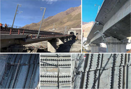

The observed difference in seismic damage between the two bridges motivated an investigation into the constraint effects of the rail on bridge seismic response. For this purpose, a finite element model (FEM) of the Liuhuanggou bridge is established by ABAQUS, which is an eight-span simply-supported girder bridge with CRTS I double-block ballastless tracks. Strong ground motion recordings from the PEER NGA-West2 data set are selected as earthquake excitations. Through numerical simulation, the dynamic responses of the bridge with and without the rail under earthquake excitations are compared. The constraint effects of the rail on the bridge are analyzed under the ground motion in the near-fault area.
2 Methodology
2.1 Simplified Analytical Model of Rail Constraint
A simplified analytical model to compare the seismic response of the bridge-track-rail system is derived first. In the model, the constraint effect of the rail varies at different positions of the bridge. In the middle span position, the rail laid on the bridge primarily serves to connect adjacent spans, thereby increasing the mass participating in the vibration, as illustrated in Figure 3a. At the side span position, the constraint effect of the rail laid on the subgrade resists the movement of the bridge. Thus, the constraint of the rail is simplified to the spring, with one end connected to the subgrade and the other to the bridge, as shown in Figure 3b. The simplified analytical model of the simply-supported girder bridge without the rail is illustrated in Figure 3c.
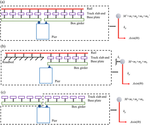
By comparing the particular solution of Equations (4-6), it can be concluded that, at different frequencies, the value of formula Equation (4) is the largest, while the value of formula Equation (5) is the smallest among the three yb values. This indicates that the constraint of rail will be against the displacement of the bridge at the side span and increase the displacement of the bridge at the middle span.
2.2 FEM of the HSR Bridge
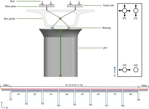
The FEM of the Liuhuanggou bridge is established by using ABAQUS, as shown in Figure 4. The girder is 32.6 m long, the adjacent girder ends are 0.1 m away from each other along the longitudinal direction, and the total length of the bridge is 261.7 m. The girder has a single box section, with a deck width of 12.0 m, a box girder height of 3.05 m, and is made of C50 concrete. The height of the round-end solid piers from P1 to P9 are 4.77, 7.5, 7.5, 9.0, 8.5, 8.5, 9.0, 9.0, and 4.966 m, respectively. The CRTS I double-block ballastless track consists of the rail, track slab, and base plate. The rail is made of 60 g/m steel, and the fasteners connecting the rail to the track slab are type WJ-8B, arranged every 0.654 m. The bearings are selected and arranged according to the construction drawings of the Liuhuanggou Bridge. TJQZ-LX spherical steel bearings are adopted, and each span of the beam is equipped with four bearings, including GD bearing, HX bearing, ZX bearing, and DX bearing. The GD bearing is the fixed bearing, which can not move transversely or longitudinally; The HX bearing is the transverse sliding bearing, which can only move transversely; The ZX bearing is the longitudinal sliding bearing, which can only move longitudinally; The DX bearing is the two direction sliding bearing, which can move both transversely and longitudinally. The four types of bearings are arranged in the same way for the middle span and the side span. The HX bearing and the GD bearing are arranged at the left end of each span, and the DX bearing and ZX bearing are arranged at the right end, as shown in Figure 4. The beam element is used to simulate the box girder, pier, track slab, base plate, and rail. The fastener and the bearing between the box girder and the pier are simulated by springs. The connection between the base plate and the bridge is assumed to be rigid. For simulating CRTS I double-block ballastless track, the track slab and base plate are considered as a unified structure. To simulate the constraint effect of the rail on the bridge laid on the subgrade, a 100 m transition section is set outside both ends of the bridge [23, 24]. The modeling of each structural layer and its connection mode is illustrated in Figure 4. The two FEMs, with-rail and without-rail cases, are identical except for the presence or absence of the rail constraint. The acceleration and displacement response of the bridge in the longitudinal, transverse, and vertical directions are mainly compared between the two cases (with-rail and without-rail).
The material properties of the rail, track slab [25], base plate [25], box girder [26] and pier [26] in the FEM of this paper are shown in Table 1. Stiffness and damping of the fasteners (WJ-8B) [25, 26, 29, 30], coefficient of friction and stiffness of the bearings [31] are shown in Table 2. For spherical steel bearings, the friction coefficient was set to be 0.03 [21].
| Sections | Elasticity modulus (MPa) | Densities (kg/m3) | Poisson ration | Damping coefficients | ||
|---|---|---|---|---|---|---|
| Component | Width × Height(m) | α | β | |||
| Rail (60 kg/m) | / | 2.06 × 10⁵ | 7850 | 0.3 | 7 | 1 × 10⁻⁶ |
| Track slab | 6.44 × 2.80 × 0.26 | 3.25 × 10⁴ | 2500 | 0.2 | / | / |
| Base plate | 6.44 × 2.80 × 0.21 | 3.25 × 10⁴ | 2500 | 0.2 | / | / |
| Box girder | 7.41032 × 2.67755 thickness: 1 m | 3.45 × 10⁴ | 1349.22 | 0.2 | 2.995 | 0.000562 |
| 2#~8#pier | 5.6037 × 2.3126 | 3.25 × 10⁴ | 1660 | 0.2 | / | / |
| 1#, 9#pier | 7.2 × 6.35 | 3.25 × 10⁴ | 2500 | 0.2 | / | / |
| Spring elements | Longitudinal stiffness (kN/m) | Vertical stiffness (kN/m) | Transverse stiffness (kN/m) | Damping (kN·s/m) | Coefficient of friction |
|---|---|---|---|---|---|
| Fastener | ±6.50/±0.005 | 3.50 × 10⁴ | 5.0 × 10⁴ | 50 | / |
| GD bearing | Rigid | 2.5 × 10⁹ | Rigid | / | / |
| HX bearing | Rigid | 2.5 × 10⁹ | 1.125 × 10⁵ | / | μ = 0.03 |
| ZX bearing | 1.875 × 10⁴ | 2.5 × 10⁹ | Rigid | / | μ = 0.03 |
| DX bearing | 1.875 × 10⁴ | 2.5 × 10⁹ | 1.125 × 10⁵ | / | μ = 0.03 |
The natural vibration frequencies of the two FEMs are presented in Table 3. From the table, it can be observed that the natural vibration frequencies of the with-rail case are slightly higher than those of the without-rail case. The natural vibration frequency of the bridge is influenced by the ratio of stiffness to mass. The mass and longitudinal stiffness of the bridge will be increased by laying the rails on the bridge. Due to the constraint of the rails having a greater influence on the longitudinal stiffness of the bridge than its influence on mass, the natural frequency of the bridge increases.
| 1 order/Hz | 2 order/Hz | 3 order/Hz | 4 order/Hz | 5 order/Hz | |
|---|---|---|---|---|---|
| With-rail case | 6.2048 | 22.404 | 32.247 | 43.639 | 67.931 |
| Without-rail case | 6.1757 | 22.367 | 31.316 | 43.634 | 67.906 |
2.3 Selection of Ground Motion Records
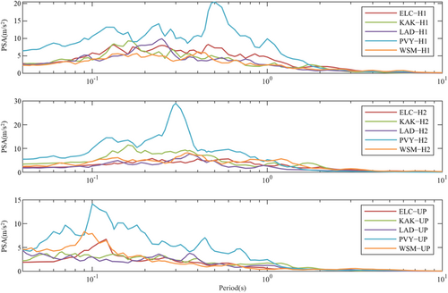
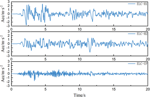
Ground motion recordings from the PEER-NGA West2 database were selected following the rules of Mw ≥ 6, RJB < 25 km, and PGA > 0.05 g [32]. All data were preprocessed (baseline adjustment and band-pass filtering) before being input into the FEM. At the same time, the ratio of PGA and peak ground velocity (PGV) of selected ground motion recordings are divided into three groups: PGA/PGV < 0.8 g/(m/s), PGA/PGV > 1.2 g/(m/s), and 0.8 g/(m/s) < PGA/PGV < 1.2 g/(m/s) to cover the possible range of the seismic responses of bridge systems. The selection criteria are described in Table 4, and the selected ground motion recordings are listed in Table 5. The response spectra of the three components of the selected ground motions are provided in Figure 5, revealing a significant difference among the ground motions. In the simulation, three components of ground motion recordings are used, with the two horizontal components applied as the excitations in the longitudinal and transverse directions, respectively. Among the three components of ground motion recordings, H1 is used for longitudinal excitation, and H2 is used for transverse excitation. Due to space limitations, only acceleration time histories for ELC-H1, ELC-H2, and ELC-UP are shown in Figure 6.
| RJB | PGA | PGV | PGA/PGV | |||||
|---|---|---|---|---|---|---|---|---|
| Earthquakes | Stations | Labels | MW | (km) | Component | (g) | (m/s) | g/(m/s) |
| Imperial Valley 02 | El Centro Array #9 | ELC | 6.95 | 6.09 | H1 | 0.28 | 0.31 | 0.90 |
| H2 | 0.21 | 0.31 | 0.68 | |||||
| UP | 0.18 | 0.09 | 2.00 | |||||
| Kobe Japan | Kakogawa | KAK | 6.9 | 22.5 | H1 | 0.24 | 0.21 | 1.14 |
| H2 | 0.32 | 0.27 | 1.19 | |||||
| UP | 0.17 | 0.11 | 1.55 | |||||
| Chalfant Valley 02 | Bishop LADWP South St | LAD | 6.19 | 14.38 | H1 | 0.25 | 0.20 | 1.25 |
| H2 | 0.18 | 0.20 | 0.90 | |||||
| UP | 0.14 | 0.07 | 2.00 | |||||
| Coalinga 01 | Pleasant Valley P.P. yard | PVY | 6.36 | 7.69 | H1 | 0.60 | 0.60 | 1.00 |
| H2 | 0.53 | 0.39 | 1.36 | |||||
| UP | 0.37 | 0.16 | 2.31 | |||||
| Superstition Hills 02 | Westmorland Fire Sta | WSM | 6.54 | 13.03 | H1 | 0.17 | 0.23 | 0.74 |
| H2 | 0.21 | 0.32 | 0.66 | |||||
| UP | 0.23 | 0.09 | 2.56 |
3 Constrain Effect of Rail on Acceleration Response of the Bridge
3.1 Comparison of Acceleration Time History for With- and Without-Rail Cases
Time histories of the longitudinal, transverse, and vertical acceleration response of the bridge at the mid-point of three typical spans (the 1#, 5#, and 8# girders) are compared under the selected earthquake excitations input at all piers. The acceleration time histories under the excitation of ground motion ELC are shown in Figure 7. The blue solid line represents the acceleration time history for the with-rail case, whereas the yellow line corresponds to the without-rail case.
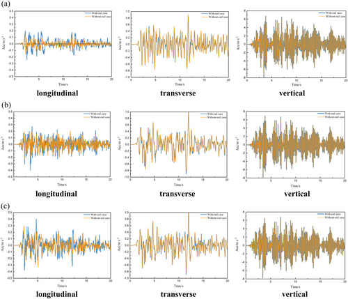
As shown in Figure 7, there is a significant difference in the acceleration amplitude of the bridge in the three directions at the same span. The vertical acceleration amplitude is the largest, followed by the transverse acceleration, while the longitudinal acceleration amplitude is the smallest. This difference could be attributed to the higher vertical stiffness of the bearings, leading to greater seismic load transfer from the pier top to the girder. Additionally, the transfer of longitudinal seismic loads to the girder is reduced due to the mutual misalignment of the pier top and the girder at the sliding bearings.
When comparing the acceleration amplitudes of girders in the same direction across different spans, it is evident that the longitudinal and transverse acceleration amplitudes of the 1# and 8# girders are higher than those of the 5# girder in both cases. In contrast, the vertical acceleration curves of the bridges at different spans are essentially the same. For longitudinal responses of 1# and 8# girders, the acceleration time histories exhibited similar trends between cases, with differences primarily in peak values. Meanwhile, the vibration period of the longitudinal acceleration time histories of the with-rail case at the middle span is longer than that of the without-rail case. This phenomenon may be attributed to the longitudinal constraint effect of the rail on the adjacent spans, which causes the different girders to vibrate together, thereby increasing the vibration period of the longitudinal acceleration in the middle span.
A significant difference in the longitudinal acceleration response of the bridge is evident when comparing the three directional accelerations of the girder in both cases at the same span. At the 5# girder, the longitudinal acceleration amplitudes of the girder under the with-rail case are approximately twice as large as in the without-rail case. In the transverse and vertical directions, the acceleration time histories of the two cases basically coincide. This may be attributed to the smaller longitudinal acceleration response of the bridge itself, which makes the longitudinal constraint effect of the rail more obvious. At the same time, the longitudinal constraint of rail also increases the response of the bridge in the longitudinal direction. A similar phenomenon to the longitudinal response of the bridge is observed when the transverse acceleration response of the bridge is small (between −0.2 m/s2 and 0.2 m/s2), and it increases under the constraint of rail. In the vertical direction, the constraint effect of the rail between adjacent spans is reduced, resulting in a smaller difference between the two cases.
3.2 Comparison of Peak Acceleration for With- and Without-Rail Cases
The peak acceleration responses in each mid-point of the span under the action of the above ground motions are extracted. The peak values for the two cases are compared by calculating the ratio of the with-rail case to the without-rail case. The constraint effect of the rail on the peak acceleration values in each direction at different spans of the bridge is then analyzed, as shown in Figure 8.

In Figure 8a, at the middle span, the peak values of longitudinal acceleration in the with-rail case are greater than that in the without-rail case. This could be attributed to the longitudinal connection of the rail at the middle span, which reinforces the bridge integrity and enhances the transfer of pier loads to the girder. In contrast, the HSR bridge without rail is a determinate structure, with only a small portion of the pier loads acting on the girder after passing through the sliding bearings. At the side span, the values for both cases become similar. This is because the side spans are influenced by both the constraint of the rails on the subgrade and the load transfer of the rails on the other spans. The constraint of the rails laid on the subgrade reduces the impact of the connection amplification effect of the middle span on the side spans to a certain extent.
In Figure 8b, the peak vertical acceleration values for each mid-point of the span in the with-rail case are essentially identical to those in the without-rail case, with no distinguishable variation between the side span and the middle span. This may be attributed to the substantial vertical stiffness of the bearings, which leads to the direct transfer of loads from the piers to the girders. This leads to the entire bridge experiencing vertical movement during the earthquake, and the constraint effect of rail is not prominent. Consequently, the peak vertical acceleration ratio between the two cases remains constant across different spans.
In Figure 8c, the difference in the peak of transverse acceleration between the two cases is insignificant. This could be attributed to the limited transverse movement of the ZX and GD bearings, which resulted in a larger transverse acceleration response of the bridge in both cases. Even though the constraint of rail enhances the bridge's integrity and increases its transverse acceleration response at the middle span, the increase is small.
Figure 8 also indicates that the difference in longitudinal acceleration for the two cases (with-rail and without-rail) is more pronounced than in the vertical and transverse directions. This may be attributed to the fact that both sliding bearings can move in the longitudinal direction, thereby reducing the longitudinal acceleration response of the bridge and making the constraint effect of rail more evident. In the other two directions, the GD and ZX bearings at the side of the beams can't move freely in the transverse direction, and each bearing has a large vertical stiffness. This leads to a significant transverse and vertical acceleration response of the bridge and a reduction in the constraint effect of the rail.
3.3 Comparison of Significant Duration for With- and Without-Rail Cases
Significant Duration (Ds) is a fundamental aspect of earthquake ground motion, defined as the time interval from 5% to 95% of the Arias intensity of the ground motion, denoted by Ds(5%–95%). It represents the duration of the bridge's vibration under seismic excitation. Comparing the Ds values of the bridge with and without rails can help determine whether the rail constraint influences the bridge's vibration duration under seismic excitation. Table 6 exhibits the Ds(5%–95%) of the acceleration response of the bridge at the mid-point of the span for both the with-rail and without-rail cases. Figure 9 indicates the percentage increase or decrease in the with-rail case compared to the without-rail case.
| Ground motion | Direction | Mid-point of 1# (with-rail/without-rail) | Mid-point of 2# (with-rail/without-rail) | Mid-point of 3# with-rail/without-rail) | Mid-point of 4# (with-rail/without-rail) | Mid-point of 5# (with-rail/without-rail) | Mid-point of 6# (with-rail/without-rail) | Mid-point of 7# (with-rail/without-rail) | Mid-point of 8#(with-rail/without-rail) |
|---|---|---|---|---|---|---|---|---|---|
| ELC | Longitudinal | 14.815/14.855 | 14.855/14.85 | 14.355/13.885 | 15.065/15.365 | 14.165/14.34 | 13.72/14.825 | 14.825/15.125 | 14.715/14.615 |
| Vertical | 14.335/14.41 | 14.42/14.49 | 14.425/14.5 | 14.43/14.505 | 14.425/14.5 | 14.43/14.51 | 14.43/14.505 | 14.315/14.34 | |
| Transverse | 14.695/14.67 | 13.695/13.865 | 15.485/15.5 | 16.37/16.26 | 16.19/16.215 | 15.305/15.285 | 15.245/15.26 | 15.63/15.585 | |
| KAK | Longitudinal | 10.825/10.985 | 12.56/12.07 | 13.27/12.5 | 12.685/11.115 | 12.655/12.405 | 12.705/12.885 | 12.89/12.545 | 12.105/12.615 |
| Vertical | 10.72/10.7 | 10.59/10.55 | 10.63/10.56 | 10.57/10.52 | 10.575/10.52 | 10.575/10.52 | 10.58/10.52 | 10.5/10.51 | |
| Transverse | 12.21/12.145 | 10.335/10.185 | 9.365/9.375 | 10.035/10.705 | 9.365/9.67 | 9.5/9.45 | 9.52/9.555 | 10.795/11.45 | |
| LAD | Longitudinal | 9.955/8.82 | 13.02/11.245 | 12.615/10.88 | 12.045/10.325 | 12.22/10.71 | 11.165/10.36 | 11.92/10.75 | 11.08/9.13 |
| Vertical | 7.575/7.695 | 7.715/7.94 | 7.72/7.93 | 7.75/7.94 | 7.715/7.925 | 7.765/7.935 | 7.725/7.95 | 7.515/7.615 | |
| Transverse | 9.26/8.995 | 9.985/9.795 | 8.555/8.425 | 6.475/6.82 | 5.62/5.7 | 7.815/7.345 | 6.965/6.225 | 7.6/7.485 | |
| PVY | Longitudinal | 8.495/8.66 | 8.77/8.47 | 9.745/9.31 | 9.4/7.91 | 9.035/8.35 | 8.705/9.45 | 7.985/9.63 | 8.89/8.69 |
| Vertical | 7.73/7.755 | 7.755/7.81 | 7.76/7.82 | 7.765/7.825 | 7.76/7.82 | 7.765/7.825 | 7.785/7.825 | 7.405/7.745 | |
| Transverse | 7.955/7.85 | 7.94/7.55 | 4.78/4.885 | 8.34/8.775 | 6.635/6.8 | 5.14/5.24 | 6.46/6.4 | 6.955/7.015 | |
| WSM | Longitudinal | 15.33/15.21 | 14.075/14.555 | 14.05/14.345 | 14.105/13.875 | 13.79/13.415 | 14.425/13.615 | 14.435/14.135 | 14.475/14.05 |
| Vertical | 15.045/15.025 | 15.045/15.015 | 15.04/15.01 | 15.04/15.01 | 15.035/15.01 | 15.04/15.01 | 15.045/15.02 | 14.85/14.83 | |
| Transverse | 11.535/11.62 | 12.53/12.7 | 12.4/12.39 | 12.36/12.43 | 12.1/12.18 | 12.54/12.63 | 11.74/12.01 | 11.72/11.755 |
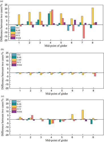
Analyzing the Ds(5%–95%) values of the bridge's acceleration response in all three directions under the two cases(with-rail and without-rail) reveals that the difference between the two cases is the smallest in the vertical direction, as shown in Figure 9. This is because the seismic load input at the base of the piers can be transferred directly to the superstructure due to the higher vertical stiffness of the piers and bearings. An analysis of the vertical acceleration time histories above also shows that the vertical acceleration response is the same for both cases, leading to only a slight difference in vibration duration. In Figure 9a, there is a significant difference in the Ds(5%–95%) values of the longitudinal acceleration between the two cases, with the with-rail case generally being larger than the without-rail case. It shows that the constraint of the rails increases the longitudinal vibration duration of the bridge. In Figure 9c, the differences between the two cases in the transverse direction are mainly concentrated within 5%, corresponding to the small effect of rail constraints on the time histories of the transverse acceleration as described above. From Table 6, different seismic inputs also significantly impact the Ds(5%–95%) values of the bridge's acceleration response. This can be attributed to the significant variations in energy and frequency across different earthquakes, which result in varying acceleration responses of the bridge under different seismic excitations.
3.4 Comparison of Fourier Acceleration Spectrum for With- and Without-Rail Cases
This paper compares the Fourier acceleration spectrum of the bridge for different earthquakes, with-rail and without-rail cases, directions, and positions, as shown in Figure 10. The values in the figure represent the differences (with-rail case minus without-rail case) between the two cases.
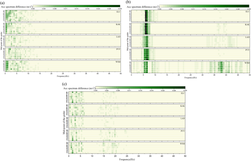
In Figure 10a, it can be observed that the longitudinal acceleration spectrum of the bridge in the with-rail case is larger than that in the without-rail case, primarily concentrated in the frequency range below 2.5 Hz. This can be attributed to the rail's constraint effect, which enhances the connectivity between the spans of the bridge, leading to an increased low-frequency response. It is also noted that the difference between the two cases is significantly larger at the middle span than at the side span. This can be attributed to the difference in the constraint effect of the rail between the side and middle spans. Additionally, the disparities between the two cases under different seismic effects exhibit variations in the frequency distribution. This can be attributed to the varying energy and frequency distributions of different earthquakes. As shown in Figure 10b, the vertical acceleration spectra differences between the two cases are predominantly concentrated near 6 Hz. This could be attributed to the fact that the rail constraints increase the natural vibration frequencies of the bridge. The peak resonance frequency of the bridge's acceleration in the with-rail case is slightly larger than that in the without-rail case, concentrating the difference around the frequency of about 6 Hz. In Figure 10c, the transverse Fourier acceleration spectrum in the range of 0–6 Hz for the with-rail case is significantly larger than that for the without-rail case. This could be attributed to the constraint effect of the rail changing the natural vibration frequencies of the bridge, resulting in a greater acceleration spectrum in the with-rail case.
4 Constrain Effect of Rail on Displacement Response of the Bridge
4.1 Comparison of Peak Displacements for With- and Without-Rail Cases
The peak displacements of three directions (transverse, longitudinal, and vertical) at each mid-point of the span under selected excitations are extracted. Aiming to analyze the distribution of maximum three-direction displacements of the bridge in different spans by considering the constraint effect of the rail. Observe whether the constraint of the rails changes the location where the bridge damage may have occurred. In this paper, we normalize the results extracted in the three directions and compute the average from the five seismic excitations, as shown in Figure 11. Moreover, we calculate the ratio of the without-rail case to the with-rail case and analyze the impact of the rail on the maximum displacement of the bridge in three directions, as shown in Figure 12.
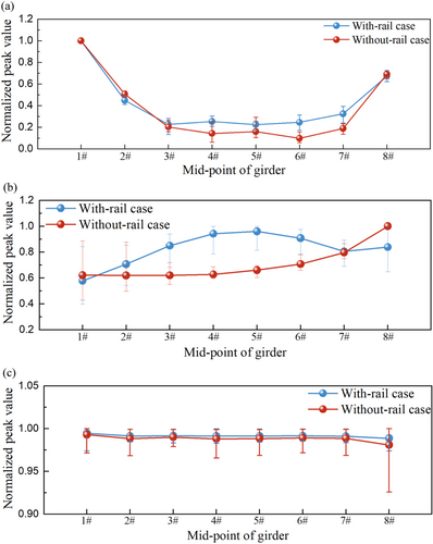
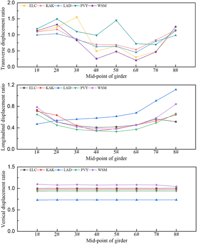
In Figure 11a, we observe that the shapes of the maximum transverse displacement curves across each span are consistent in both cases. This similarity may result from the transverse constraint provided by the bearings and the bridge tracking the transverse movement of the pier top. The maximum transverse displacement curves for both cases exhibit a pattern of larger displacements existing in 1#and 8# spans and smaller displacements existing in 4#and 5# spans. This indicates that the bridges for both cases are susceptible to damage at the side spans due to excessive transverse displacements. Therefore, it is necessary to focus on comparing the maximum values of transverse displacements of the bridges at the side span for both cases. Figure 12a indicates that the transverse displacements of the bridge without rails in the 1#and 8# spans are greater than those with rails. This could be attributed to the transverse constraint exerted by the rail laid on the subgrade at the side span positions. This results in the bridge experiencing transverse tensile forces from the rails while following the transverse movement of the pier top. This indicates that the constraint of the rails can reduce the transverse displacement of the side spans and thus reduce the damage of the bridges in the transverse direction under seismic excitations.
Figure 11b reveals a significant change in the position of the peak longitudinal displacement of the bridge after considering the constraint of the rail. In the without-rail case, the maximum longitudinal displacement of the bridge occurs at the 8# span. However, after considering the constraint of the rail, the maximum longitudinal displacement shifts to the 5# spans. The curve of the with-rail case shows an initial increase followed by a decrease, while the curve of the without-rail case exhibits a gradual increase along the bridge. For the without-rail case, this could be due to the main girder on the right side exhibiting greater displacement freedom in the longitudinal direction, with the longitudinal displacement of the girder gradually accumulating and increasing. Therefore, it is necessary to focus on the effect of the rail constraint on the longitudinal displacement response of the bridge at 5# and 8# spans. Figure 12b shows that the peak longitudinal displacement of the with-rail case is larger than that of the without-rail case at the 5# span position. This could be attributed to the influence of the longitudinal connection of the rail in the middle span position, causing adjacent beams to move together and increasing longitudinal displacement. This is similar to the conclusion obtained from the previous theoretical formula. The ratio of the without-rail case to the with-rail case at the 8# span position is larger than that at the 5# span position but still less than 1. It can be seen that although the longitudinal constraint of the rails laid on the subgrade reduces the longitudinal displacement of the bridge at the 8# span, the overall longitudinal connection effect of the rails has a greater impact on the bridge. Therefore, the continuously welded rails laid on the simply-supported girder bridge should be subjected to additional seismic measures in the middle spans.
From Figure 11c, the shapes of the two curves are essentially identical, indicating that the maximum vertical displacement of each span is essentially the same. Figure 12c also shows that the ratio of the peak vertical displacements of the two cases is basically around 1 at different positions of the bridge. This is because of the uniform excitation applied in this paper, resulting in the same vertical displacement at the bottom of each pier. Moreover, the vertical stiffness of the bearing is large, and the bridge follows the vertical movement of the pier top. The rails move vertically along the bridge, and there is no significant relative displacement between the spans. Therefore, the rail has a small constraint effect on the peak vertical displacement. Although the rails on the subgrade constrain the movement of the bridge at the side span, the impact on the peak values is not significant due to the bridge's substantial response to seismic excitations.
4.2 Comparison of Displacement Time History for With- and Without-Rail Cases
Due to space limitations in this article, the time histories of the longitudinal, transverse, and vertical displacement of the bridge at the typical positions are compared. The transverse displacement time history is extracted from the mid-point of the 1# girder, as shown in Figure 13. This is because the transverse displacement at the 1# girder is the largest for both cases across the entire bridge. Due to the similarity in the vertical displacement time histories across each span, the mid-point of the 5# girder is selected, as depicted in Figure 14. The longitudinal displacement time history is extracted from the mid-point of the 5# girder. This is because the longitudinal displacement of the middle span is the largest for the with-rail case, as illustrated in Figure 15.
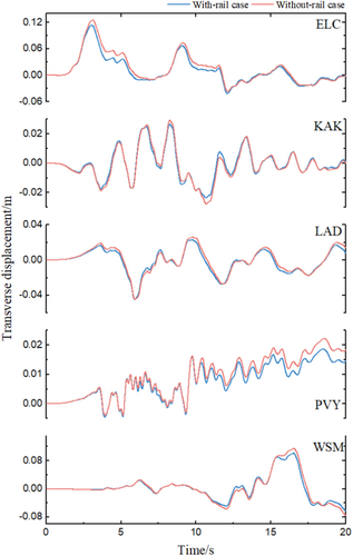
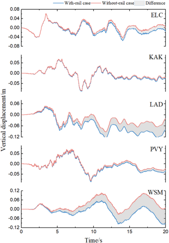
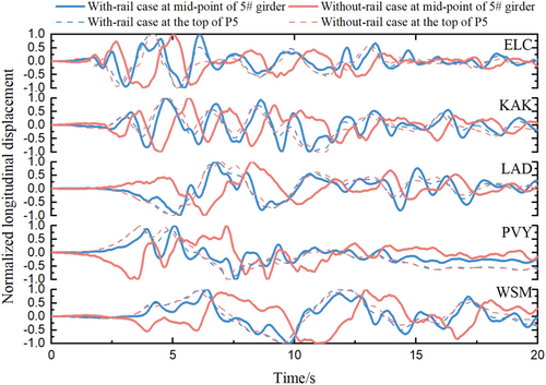
Figure 13 illustrates that, although there are variations in the shapes of the transverse displacement time histories for the two cases (with-rail and without-rail) under different seismic excitations, all curves indicate that the transverse displacement near the peak value decreases by considering the constraint of rail. This may be due to the bridge being constrained by the rail laid on the subgrade, which reduces its transverse displacement response. The figure also reveals that the time histories of the two cases coincide on a small transverse displacement response of the bridge under the same seismic excitation. This indicates that the transverse constraint effect of the rail is affected by the magnitude of the bridge's transverse response.
Figure 14 shows that the vertical displacement time histories exhibit the same shape under the same seismic excitations for both cases. This may be due to the fact that the vertical displacement of the beam in this paper mainly depends on the input of the pier bottom. The vertical displacement time histories of the two cases basically coincide within 2.5 s under the same seismic excitation. As time progresses, the vertical displacement difference between the two cases increases. This is not only related to the constraint effect of the rail but also to the seismic excitations in the other two directions. A comparison of the longitudinal displacement time histories for the two cases also shows a large difference after 2.5 s.
Figure 15 reveals an obvious phase difference in the longitudinal displacement time histories between the two cases. This may be due to the fact that the constraint of rail enhances the integrity of the bridge, causing the beam to move together with the pier. However, the integrity of the simply-supported girder bridge without rails is poor, and the longitudinal displacement trend of the beam is opposite to that of the pier top. The figure also illustrates that the longitudinal displacement response of the bridge of the with-rail case experiences a delay of approximately 0.5 s after the movement of the pier. This could be attributed to the transmission of seismic load from the pier top to the girder through the bearings, leading to a noticeable lag between the girder and the pier top.
The longitudinal displacements of the left side beam joint (exhibit greater displacement freedom) and the pier top are extracted under five seismic excitations. The difference between the longitudinal displacement of the beam joint and the pier top is used to analyze the influence of the rail constraint on the girder falling, as shown in Figure 16. In addition, the ratio of the difference in longitudinal displacement between the beam joint and the pier top to the distance from the beam joint to the bearing is calculated. The difference between the two cases (with-rail and without-rail) is then compared to analyze the probability of the girder-falling across different spans under the constraint of rail, as shown in Figure 17.
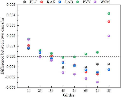
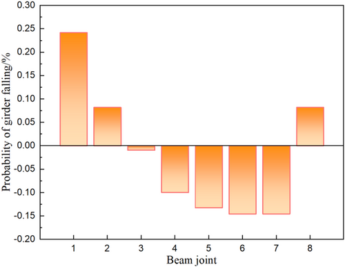
At the middle span position, the difference in the longitudinal displacement between the girder and the pier top decreases by considering the constraint of the rail. This could be attributed to the longitudinal rail constraint, which enhances the integrity of the bridge. Consequently, the girder follows the pier top during the longitudinal movement, thereby reducing the longitudinal displacement difference between the girder and the pier top. In the without-rail case, there is no constraint between adjacent beams. As a result, the beam in the without-rail case does not follow the longitudinal displacement of the pier top, leading to an increased occurrence of girder-falling in this scenario. It can also be observed from Figure 17 that the probability of the girder-falling is smaller in the middle span for the with-rail case than in the without-rail case. In contrast, the longitudinal displacement difference between the beam and the pier top increases at the side span position by considering the constraint of the rail. This indicates that in the with-rail case, girder-falling disasters are more likely to occur at side spans. This may be due to the side span beam being subjected to forces from both the pier and the rail on the subgrade, thereby increasing the longitudinal displacement difference between the beam and the pier top.
5 Conclusions
In this paper, a FEM of the Liuhuanggou bridge is established by ABAQUS, which is an 8-span HSR simply-supported girder bridge. Based on the simulation, the acceleration and displacement response of the bridge were calculated and the constraint effects of the rail on the bridge were analyzed. The main conclusions include:
- 1.
The acceleration and displacement responses of the bridge exhibit significant differences under various seismic excitations. Nevertheless, the constraint effect of the rail on the bridges shows slight sensitivity to characteristics of different seismic excitations. The natural vibration frequency of the bridge will be increased slightly by considering the constraint effect of the rail. The constraint effect does not significantly affect the vertical and transverse acceleration response of the bridge. In contrast, the constraint effects of rail are more apparent in the longitudinal direction than in the other two directions.
- 2.
Under seismic excitations, the vertical acceleration and displacement response of each span are essentially the same for both cases. The constraint effect of the rail on the vertical response of the bridges shows slight sensitivity to different spans; The Fourier spectrum of vertical acceleration for the with-rail case is significantly larger than that for the without-rail case at 6 Hz.
- 3.
The rail constraint did not significantly change the distribution of the maximum values of the transverse response across the bridge spans. The transverse displacement response for both cases indicates that the side span exhibits a large displacement, while the middle span shows a small displacement. Moreover, influenced by the rail laid on the subgrade, the transverse displacement of the side span in the with-rail case is reduced by 10.71% on average compared with the without-rail case. The constraint of the rails will reduce the damage to the bridge at the side spans due to excessive transverse displacements.
- 4.
Under near-fault earthquakes, the constraint effect of the rails increases the longitudinal response of the bridge and changes the distribution of the longitudinal displacement maximum across the bridge. This also resulted in the largest longitudinal displacement response at 5# span for the with-rail case, and the average was 2.3 times that for the without-rail case. Meanwhile, the longitudinal constraint of the rails enhances the integrity of the bridge and coordinates the movement of the girders and piers. This constraint effect also reduces the longitudinal displacement difference between the girder and the pier, thus reducing the probability of the bridge dropping a girder at the middle span.
Acknowledgments
We gratefully acknowledge the Pacific Earthquake Engineering Research Center (PEER) for the data support. This work is supported by the Joint Research Fund for Earthquake Science launched by the National Natural Science Foundation of China and China Earthquake Administration (U2039208); and the National Natural Science Foundation of China (52278467).
Conflicts of Interest
The authors declare no conflicts of interest.


