Application of Polyimide-based Microfluidic Devices on Acid-catalyzed Hydrolysis of Dimethoxypropane
Abstract
Microfluidic devices intensify transport phenomena and can improve chemical processes. New manufacturing processes and materials are perpetually developed due to constantly growing interest in process intensification. In this contribution, the authors present the design and application of polyimide-foil-based microfluidic mixing devices manufactured by reactive ion etching. As appropriate model reaction system, acid-catalyzed 2,2-dimethoxypropane (DMP) hydrolysis was chosen and investigated in three different mixing structure with varying flow rate. Energy dissipation rates were calculated to estimate mixing performances. The results show good mixing quality for Reynolds numbers between 10 and 100 and similar mixing times scales for all investigated microstructured mixers.
1 Introduction
With steadily growing interest and development in modern chemistry, life science, and pharmaceutical manufacture, research as well as industry have to face challenges, which cannot be treated by using conventionally sized plants. Microfluidic applications adapt necessary requirements to overcome limits set by the dimensions of macroscopic devices and led to a growing field of research in recent years 1. These applications are used to perform reactions rather in continuously operated processes instead of conventional batch 2.
Enhanced performance parameters such as heat and mass transfer rates lead to higher efficiencies, also known as process intensification in miniaturized equipment. These improved transport rates feature purposes such as rapid mixing or facilitated temperature control of highly exothermic reactions 3. Since diffusive mass transfer is the key parameter within microfluidic applications, micromixers are designed in a way that diffusive transport length scales are minimized. This is achieved when convective mass transport is induced and the surface boundary layer between reactants is enlarged. Especially fast reactions benefit from rapid mixing and improved heat transfer. Hence, there is a need to overcome limitations set by prevailing laminar flow. Microscopic-scaled devices show improved mixing efficiency compared to macroscopic mixers. In addition, passive micromixers stand out through low fabrication costs, easy integration into microfluidic systems, and without any need of complex process control units or additional energy input 4.
As a result of industrial development, microfluidic applications become increasingly important, so that new and improved manufacturing processes and designs for microreactors or other microfluidic systems must be constantly improved. For the development of new microfluidic devices, the material selection is of decisive importance. Polyimide (PI) is classified as a high-performance polymer due to its properties and so far, it has been used in electronics, aeronautics, and space technology. Due to its thermal stability and resistance to solvents as well as acids and bases, it is ideally suited for chemical applications, too 5.
Flexibility, low cost, and reproducibility are the main requirements, which should be met by a manufacturing process for microfluidic devices suitable for different applications. Thin-film technology is employed in thin-film deposition processes, a technology that is applied in many large-scale electronic applications such as mass production of transistors, actuators, and sensors. Reactive ion etching provides a high anisotropic etching behavior and an adjustable etching mechanism since the gas composition used for etching can be varied during the fabrication steps. The combination of both processes is evaluated in this contribution as a manufacturing process for PI-based microstructured devices characterized by a high spatial resolution and a highly anisotropic etching mechanism suitable to produce rectangular microchannels.
Applying beforehand optimized process parameters 6, three micromixing structures were manufactured. To gain deeper insight into the mixing efficiency of each produced microstructure, a consecutive and competitive reaction scheme as the acid-catalyzed hydrolysis of 2,2-dimethoxypropane (DMP) with the neutralization of hydrochloric acid with sodium hydroxide allows statements about the mixing behavior inside the structure. Rinke et al. 7 and Schwolow et al. 8 investigated this parallel reaction to obtain information about mixing performance inside several microreactors.
Evaluation of the mixing performance of each micromixer is carried out using an online UV/Vis spectroscopy for reaction monitoring and subsequent calculation of the yield of the reaction regarding acetone.
2 Design of Mixing Structures
The investigated microstructures are designed in a way to achieve efficient mixing of aqueous single-phase flows as well as multiphase flows. Literature provides various geometries to generate mixing within different microscopic scaled applications. 9
2.1 Tangential Mixer
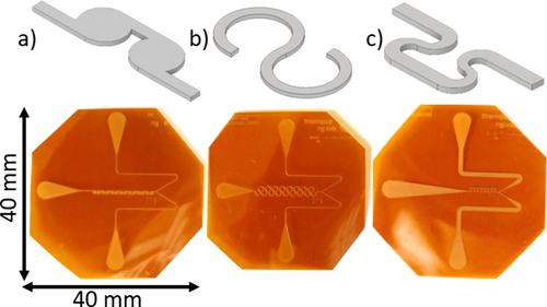
The designed tangential mixer consists of totally 14 mixing chambers arranged in series. They are connected by constriction channels featuring a width of 200 µm, which are tangentially aligned to smoothly introduce the fluid into the mixing chamber creating self-circulation. Within these constrictions, the fluid is accelerated and the distance for diffusive mass transfer is reduced. The ratio of the diameter of the circulation chamber to the width of the constriction as a crucial design parameter was set to 4.1 according to the tangential mixers designed by Ansari and Kim 10 and led to a diameter of the circulation chamber of 800 µm. The distance between consecutive mixing chambers is 1 mm.
2.2 Dean Mixer
The investigated Dean mixer consists of 15 loops. They feature a consistent channel diameter of 200 µm over the whole mixing length. The circumference of each loop is 5π/6, which results in an opening angle of 60°. The inner radius of the loops is 567 µm; consequently, the outer radius is 767 µm. The distance between two consecutive loops on the same symmetry axis is 1.6 mm. The dimensions were determined based on the investigations of Ugaz et al. 11 and Schönefeld et al. 12.
2.3 SZ Mixer
SZ mixers are common micromixing structure with a variety of applications 13 and consist of four alternating S and Z shaped loops. Each S element is connected to a Z element by an 800 µm long and 200 µm wide straight channel and the other way around. In a direct transition from one curve to the next, the channels are narrowed to 120 µm in widths. This constriction enhances diffusive mixing due to shorter diffusion length and accelerates the fluid. The geometry was created according to Tollkötter et al. 14.
2.4 Manufacturing Process
The manufacturing process is divided into two main parts. First, for creating a hard mask from aluminum on the PI foil, the PI substrate is cut und cleaned. Photoresist is spun onto the surface of the substrate by spin coating. After baking, the resist is exposed to UV light and developed to create a negative of the wanted mask structure. To gain the positive mask, the PI foil is covered with aluminum by high-frequency cathodic sputtering. Unwanted aluminum is removed by lift-off with acetone. Subsequently, reactive ion etching is used as a bulk structuring strategy to generate the desired microchannels within the PI foil. 6
3 Experimental Setup
The experimental setup as shown in Fig. 1 consists of two syringe pumps (VIT-FiT, Lambda Instruments GmbH, Barr, Switzerland) with 50-mL syringes (Henke-Ject, Henke-Sass Wolf GmbH, Stuttgart, Germany) and a thermostat (Polystat cc2, Peter Huber Kältemaschinenbau GmbH, Offenburg, Germany), in which the two feeds are preheated to 25 °C. Insulated tubes connect the pumps to the microreactor. Fig. 2 presents the in-house custom-made mixing structures manufactured by reactive ion etching. Here, Kapton® HN (E. I. du Pont de Nemours and Company, Wilmington, USA) with a thickness of 125 µm was utilized as substrate.
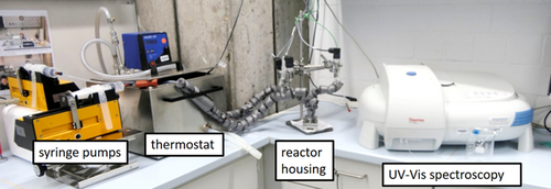
All tubes are connected via Hy-Lok compression fittings (Hy-Lok D Vertriebs GmbH, Germany). A reactor housing links the tubing with the PI-based mixing structures 6. Tab. 1 demonstrates characteristic data for all investigated mixing structures at a volumetric flow rate of 1.635 mL min−1, which corresponds to the highest possible pressure drop of 2.5 bar in the Dean 1 mixer.
|
Mixer type |
Mixing volume Vmix [µL] |
Hydraulic residence time |
Aspect ratio a [–] |
Reynolds number Re [–] |
Root mean square roughness Rq [µm] |
Hydraulic diameter dh [µm] |
|---|---|---|---|---|---|---|
|
Tangential |
0.948 |
3.5 |
0.501 |
181.6 |
2.1 ± 0.6 |
134.1 |
|
Dean 1 |
1.085 |
4.0 |
0.464 |
186.2 |
1.7 ± 0.3 |
127.2 |
|
Dean 2 |
1.288 |
4.7 |
0.550 |
175.8 |
4.0 ± 2.0 |
141.1 |
|
SZ |
0.306 |
1.1 |
0.864 |
243.7 |
3.0 ± 2.0 |
110.3 |
For evaluation of reaction progress and mixing quality, sensory for temperature (IKF 05/10, ES Electronic Sensor GmbH, Heilbronn,Germany) and pressure (WIKA Alexander Wiegand SE & Co. KG, Klingenberg, Germany) is installed at both inlets and the outlet. The data obtained is supplied to a LabVIEW (National Instruments Germany GmbH, Munich, Germany) interface monitoring and storing measured signals. An UV/Vis spectrometer (Thermo Scientific Evolution 201 spectrometer, Schwerte, Germany) delivers online concentration measurements with a measurement interval of 0.1 s. A confocal laser-scanning microscope (VK-X 100, Keyence, Neu-Isenburg, Germany) enabled the evaluation of the quality of the etched surface and was used to determine the root mean square roughness as shown in Tab. 1. The difference of properties between Dean 1 and Dean 2 mixers results from a higher etching depth for Dean 2 mixer. For both channels the width is identical with 200 µm but the etching depths are 95 and 113 µm, respectively.
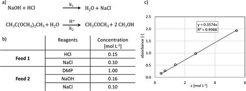
The reaction scheme of the acid-catalyzed DMP hydrolysis as well as the competitive neutralization reaction are shown in Fig. 3a. Fig. 3b displays feed compositions according to Rinke et al. 7. UV/Vis measurement of acetone was calibrated in actual solvent mixture as it is used in the feed including 0.1 mol L−1 NaCl. The resulting calibration line at a wavelength of 271 nm is shown in Fig. 3c.
4 Results and Discussion
Evaluating the mixing quality of the microstructures, the volumetric flowrates and, thus, the Reynolds number were varied, and the obtained yields of acetone measured via UV/Vis spectroscopy are presented in Fig. 4. As expected, the yield decreases with increased volumetric flow rate and Reynolds number. For Reynolds numbers higher than 40, all mixing structure reveal acetone yields below 1 %. For higher Reynolds numbers a further decreasing of the yield could not be observed.
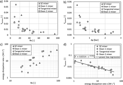
For Reynolds numbers lower than 35, the obtained yields for the tangential mixer decrease moderately from 2.2 % to about 1 %. Both Dean mixers behave differently as the yields for Dean 1 falling from 3.3 % to 1 % but the yield obtained with the Dean 2 reduces from 2.2 % down to 0.7 %. The SZ mixer shows the highest yields between 3.5 % and 5.2 %. For better comparison of the data, the obtained yields are plotted against the measured pressure loss over the mixing length; as shown in Fig. 4b.
 ()
()The energy dissipation rate is derived in accordance with Eq. 1 from the pressure drop Δp, the volumetric flow rate  , and the mixing volume V, which is responsible for the measured pressure drop. The acetone yield is plotted logarithmically against the energy dissipation rate in Fig. 4d. The plots are linearized, where the similar relation of energy dissipation rate and yield of acetone can be observed for all mixing structures. A power law regression was fitted to the experimental data obtaining an exponent n = –0.56, which is close the theoretical value of –0.5 15-17.
Holvey et al. 13 measured methanol yield instead of acetone for evaluating the same reaction system and reached comparable methanol yields below 0.1 using a caterpillar mixer with a hydraulic diameter of 600 µm. A comparison of the results of Holvey et al. and the results of this study shows an energy dissipation rate 10 000 times lower. For similar energy dissipation rates between 1 and 50 W L−1, tangential mixers realized methanol yields between 0.4 and 0.65 13.
Overall, all four investigated structures display almost similar mixing qualities, leading to the conclusion that the structure has only a minor effect on the mixing quality for the investigated Reynolds number range and all four mixing structures operate at the same mixing time scale.
5 Conclusion and Outlook
Four microfluidic devices manufactured by a newly developed reactive etching process were applied on a mixing-sensitive consecutive reaction system. By implementing a test rig including online UV/Vis spectrometry, it was possible to measure the resulting acetone concentration after the mixing structures. By relating the derived yield regarding acetone with the Reynolds number, fast mixing of all investigated microstructures leads to a yield below 1 % for Reynolds numbers between 40 and 80.
Finally, the correlation of the yield regarding acetone with the specific energy dissipation rate indicated similar mixing time scale for all investigated micromixers. In contrast to results found by Holvey et al. 13 for mixers with 10 times larger hydraulic diameters and similar energy dissipation rates between 2 and 40 W L−1, the evaluated mixing structures of this work show single digit acetone or methanol yields, respectively, for all investigated process parameters.
Reactive ion etching is suitable as a fast and easy manufacturing technique for microfluidic devices in the micrometer range with rectangular channel geometries. This application shows the possibility to manufacture microstructures when they are needed in the lab leading to a fast installation of an experimental setup and accelerated process development.
As an outlook, the manufacturing process needs to be revised and optimized regarding reproducible of channel depths and roughness. Especially, the photolithography process is to be optimized as inclination angles of the photo resist, affect the aspect ratio and the precise etching of the channel. For further applications, mixing-sensitive nucleophilic additions as lithiations are attractive, since single addition is needed and the multiple addition should be avoided.
Acknowledgements
The authors thank the Smart Microsystems Institute, TU Dortmund University, for providing the technology of reactive ion etching, photolithography, and fruitful discussions. Open access funding enabled and organized by Projekt DEAL.
Symbols used
-
- a [–]
-
aspect ratio
-
- c [mol L−1]
-
concentration
-
- dh [m]
-
hydraulic diameter
-
- p [bar]
-
pressure
-
- Rq [m]
-
root mean square roughness
-
- Re [–]
-
Reynolds number
-
- T [°C]
-
temperature
-
- V [m3]
-
volume
-
- Y [–]
-
yield
Greek letters
-
- ε [W L−1]
-
specific energy dissipation rate
-
- τ [s]
-
hydraulic residence time
Sub- and Superscripts
-
- 0
-
start
-
- mix
-
mixing
Abbreviations
-
- DMP
-
2,2-dimethoxypropane
-
- PI
-
polyimide


 [ms]
[ms]
