Polymer Film Heat Transfer Surfaces in Seawater Desalination: Fouling Layer Formation and Technology
Abstract
The emerging polyether ether ketone (PEEK) films were evaluated as future heat exchanger materials in seawater thermal desalination processes. Fouling resistance curves were measured in a pilot plant for pure PEEK films, talcum-filled PEEK films, and stainless-steel films with artificial seawater, showing that pure PEEK films have the advantage of weaker forces of adhesion or cohesion between the scaling materials and the film surface. Increasing the flow rate from 18 to 24 L min−1 results in decreases of both the fouling rate and the asymptotic values. This was attributed to the lower polarity of 10.4 %, the lower arithmetic average roughness of 0.06 μm, and the homogeneous topography of the PEEK film. This polymer film is adaptable to in situ cleaning in thermal seawater desalination processes.
1 Introduction
Seawater desalination is a separation process currently applied on the industrial large-scale level to tackle the scarcity of natural water supplies in many regions that may experience drought due to climate changes 1. However, a major problem encountered in the desalination industry is the scaling or fouling of heat exchangers due to crystallization of the hardly soluble inorganic salts in seawater, mainly calcium carbonate, calcium sulfate, magnesium carbonate, and magnesium hydroxide. In conventional thermal desalination plants such as multiple-effect distillers (MED) and multi-stage flash (MSF) distillers, scale deposits have an adverse influence on the performance of the heat transfer units, which results in serious losses of efficiency and production capacity 2. To compensate for the influence of scaling, a substantial additional capital cost is required to oversize the heat transfer area. In addition, the scaling problem generates additional running and operating costs because of the need for the continuous feeding of scale reduction chemicals and due to process shutdown for cleaning and maintenance 3, 4.
The fouling process of heat exchangers depends on many interconnected variables related to the seawater and the heat transfer surface. The seawater salinity (concentration), the temperature, supersaturation with respect to scaling salts, the pH, and the flow rate are key variables affecting the crystallization fouling from seawater 5. On the surface side, there is an interaction between the surface and the particles (nuclei) that have formed at the liquid/surface interface. The induction of scaling mainly depends on the adhesion forces between the formed scaling particles and the surface 6. In addition, the chemical composition, roughness, adsorption characteristics, charge, and nanostructure of the surface significantly alter the surface energy and thus the adhesion between the surface and the scaling particles 7. These interactions can promote or prevent adhesion of the scaling particles 8-10. In order to initiate nucleation at the surface, free and active nucleation sites on the surface must be available to catalyze the start of scaling. This critical property of the surface depends mainly on the topography and roughness of the material used in the construction of the heat transfer equipment.
Due to the need for high production capacities, heat exchangers in the seawater desalination industry are conventionally made from high-thermal conductivity and scaling-resistant special metals and alloys such as stainless steel (S.S.), copper, aluminum, Inconel X, Cu-Ni 90/10, Hastelloy A, and titanium 11, 12. These materials are quite expensive and have a high affinity to scaling due to their high surface energy. Application of metal alloys in the desalination industry requires cleaning processes and the addition of anti-scaling chemicals, to control the fouling problems. Therefore, research and developments are promoted in the direction of identifying novel heat transfer materials that are of low cost and less susceptible to scaling problems.
As an alternative to conventional metallic materials, polymeric-tube bundled heat exchangers were developed for special applications in the pharmaceutical and chemical industries due to their high resistance to corrosion 13. However, their application in seawater desalination is constrained because of their low thermal conductivity compared to metallic alloys 14, 15. A possible solution to implement polymeric materials in seawater desalination is by using a polymeric thin-film heat transfer medium 16. A novel-design polymer film heat exchanger (PFHX) with very thin polymer films (25 μm) made of polyether ether ketone (PEEK) films was successfully tested, and a high overall heat transfer coefficient (3765 W m−2K−1) was achieved 17. A PEEK PFHX for MED seawater desalination was investigated by Christmann et al. 18. Their results demonstrated that a PEEK polymer film of 25 μm thickness, in combination with appropriate spacer geometry, is sufficient for mechanical stability in MED plants.
There are several published studies on the fouling behavior of polymer films in single-salt solutions. Dreiser et al. 19 investigated the kinetics and quantity of crystallization fouling on different polymeric surfaces for a single model salt of CaSO4 and CaCO3. The results obtained demonstrated that polymeric surfaces (PEEK Aptiv®) can be utilized in thermal desalination plants. The heat transfer performance and wetting behavior of PEEK films in the case of phase change have been studied in detail by Bart and Dreiser 20, by conducting a series of scaling experiments with the single salts, CaSO4 and CaCO3. The results demonstrated that PEEK films hold good potential in industrial seawater desalination due to their low scaling tendency, with the advantage of cleaning-in-place.
The crystallization fouling on PEEK polymeric films was investigated intensively in environments containing only a single model salt solution of either calcium sulfate or calcium carbonate. However, very limited systematic research is available about crystallization fouling on PEEK polymeric film surfaces in a real seawater environment with mixed-salt fouling. Moreover, the performance of PEEK polymeric films as future heat exchangers for the desalination industry are still not well understood. Therefore, it is necessary to acquire data for the design of PEEK polymer film-based heat exchangers for desalination plants such as the MED, which operates under vacuum and at low temperatures.
This work represents a study of the scaling behavior of PEEK polymeric surfaces in seawater, with an emphasis to investigate their applicability to seawater desalination plants. The scale layer characteristics such as its adhesion, composition, ease of removal, and in situ cleanability were analyzed. Moreover, the surface roughness and topography of polymer PEEK films and their influence on the fouling process were studied.
2 Theoretical Background
 (1)
(1) (2)
(2)where mf (kg−1m−2) is the amount of mass deposition on a unit heat transfer surface, Kf (W m−1K−1) is the thermal conductivity of the fouling layer and ρf (kg m−3) is the density of the fouling materials.
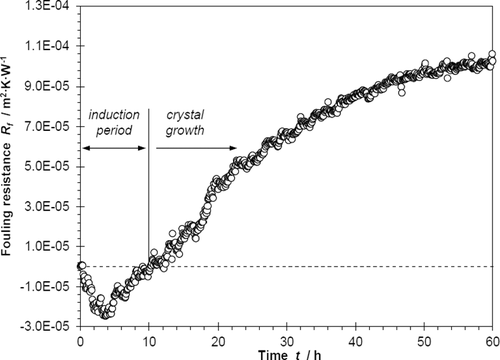
Fig. 1 illustrates that the variation of the fouling resistance with time is divided into two stages: the negative range (enhanced heat transfer) and the positive range (reduced heat transfer). The negative fouling resistance during the induction period is attributed to the fact that the generated nuclei, which act as the ground for building the fouling layer, when adhering to the surface create extra roughness and therefore enhance the turbulence for the flowing fluid, thus increasing the convective heat transfer rate 23.
 (3)
(3)where τ (s) is the induction time, T (K) is the absolute surface temperature, σ (J m−2) is the surface free energy, θ (°) is the contact angle of the crystal on the surface, and C1 and C2 are constants of the system.
 (4)
(4) (5)
(5) (6)
(6)Here, Cb (kgparticles kgSW−1) is the concentration of the fouling material (particles) in the bulk of the fluid, B (m2) is the fluid flow cross-sectional area, St (–) is the stickability, k1 (–) is a proportional constant, and As (m2) is the heat transfer surface area.
3 Experimental
3.1 Equipment
Fig. 2 illustrates the flow diagram of the pilot scale equipment that was used for investigating the crystallization fouling experiments of inversely soluble salts from seawater on a polymer film heat transfer surface. The prepared artificial seawater is stored in the feed tank (1) and is circulated through the test compartment (4), which contains the heat transfer polymer film, using the circulation pump (2) (Type MPN 170; Schmitt-Kreiselpumpen). The circulated seawater passes through a cartridge filter (3) to ensure the absence of particulates or any suspended solid particles.
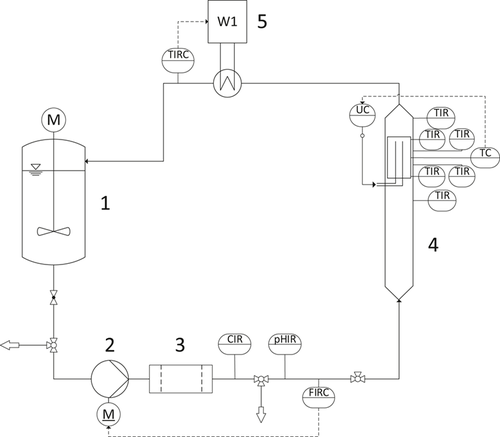
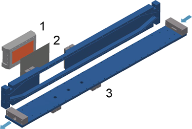
The test compartment (4) is a vertical rectangular duct made from poly(methyl methacrylate) (PMMA) equipped with a removable heating block (Fig. 3), which can be fitted on a designated opening as an integrated part of the wall. The heating block is made of copper, which is heated electrically by using two heating elements (Maxiwatt®; 230 V/1000 W). The polymer film is wrapped on the copper surface, providing a heat transfer area of 128 cm2. The heating block is insulated by a polyoxymethylene shell to guarantee unidirectional heat flow towards the heat transfer surface.
A combined automatic control and instrumentation system for the volumetric flow rate (F), the bulk seawater temperature (TB), and the hot surface temperature (TS) is installed to enable the performance of long-period experiments under controlled variables. Three temperature sensors (Pt 100, 1/3 DIN) were placed inside the heating block and four sensors were inserted in the bulk of the fluid. The circulated seawater temperature (TB) was controlled using a shell-and-tube heat exchanger as assessed by the thermostat (5) (Lauda RP 1845C).
3.2 Materials
Artificial seawater was prepared with different salinities according to the salt mole fractions suggested by Ripley and Chester 26. Analytical-grade salts (p.a., purity > 99.5 %) were added to deionized water for the preparation of the test solutions. The salts used in this study were NaCl (Roth), Na2SO4 (Riedel-de Haën), KCl (Merck), NaHCO3, KBr (Merck), H3BO3 (Riedel-de Haën), NaF (Riedel-de Haën), MgCl2·6H2O (Merck), CaCl2·2H2O (Merck), and SrCl2·6H2O (Fluka).
In this study, the investigated heat transfer polymer films were Lite TK 25 (pure PEEK, semi-crystalline; henceforth referred to as PEEK) and Lite TKT 30 (PEEK, semi-crystalline, with 30 % talcum as filler; henceforth referred to as PEEK-Talc), obtained from Lite GmbH (Gaflenz, Austria). Additional experiments were performed with S.S. 1.4301 sheets as a reference. The mechanical and thermal properties of the investigated heat transfer surfaces are listed in Tab. 1.
|
Heat transfer film |
Composition |
Thickness [μm] |
Thermal conductivity [W m−1K−1] |
Modulus of elasticity [N mm−2] |
Density [kg m−3] |
|---|---|---|---|---|---|
|
PEEK |
polyether ether ketone, semi-crystalline |
25 |
0.25 |
3200 |
1300 |
|
PEEK-Talc |
polyether ether ketone plus 30 % talcum as filler, semi-crystalline |
35 |
0.43 |
6000 |
1540 |
|
S.S. 1.4301 |
stainless steel |
25 |
15 |
200 000 |
8000 |
3.3 Experimental Methods
The experiments were conducted to evaluate the fouling behavior of different heat transfer films in seawater in different ranges of operating conditions. At the start of each experiment, the whole equipment was washed several times by circulating deionized water for a long period; then, an amount of 50 L of a pre-prepared artificial seawater with definite salinity was added to the feed tank. The investigated heat transfer film was cleaned with deionized water, dried and then wrapped on the copper surface of the heating block. During a long-period experiment, the flow rate, the bulk temperature of the seawater, the hot surface temperature, the pH, and the electrical conductivity were measured and controlled automatically. The variation of the fouling resistance of the investigated film with time was measured at constant surface temperature of 75 °C and a seawater bulk temperature of 30 °C. At the end of the experiment, the tested heat transfer film and the fouling layer were removed together, to analyze the scaling layer characteristics.
4 Results and Discussion
4.1 Fouling Resistance Analysis
Fig. 4 presents the measured change in fouling resistance with time as a result of the crystallization fouling of mixed hardly soluble salts from artificial seawater on the polymer films, PEEK, PEEK-Talc, and S.S. 1.4301 sheets. All the measurements presented in Fig. 4 were conducted at the same surface temperature (TS = 75 °C), seawater bulk temperature (TB = 30 °C), salinity (45 g L−1), and flow rate (F = 18 L m−1) under fully developed turbulent flow conditions 27.
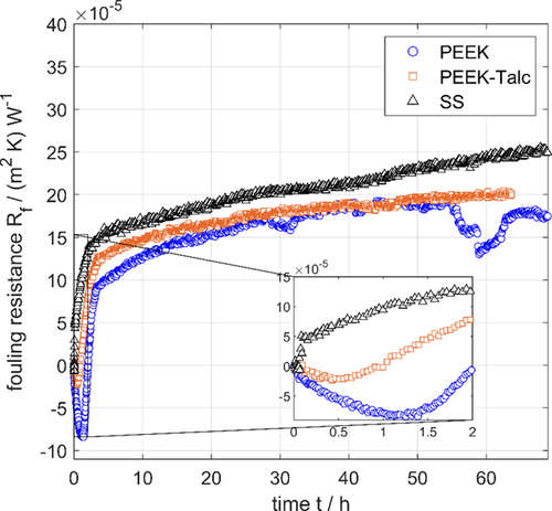
By examining the measured fouling resistance curves during 70 h of operation (Fig. 4), it is clear that the PEEK film exhibits the longest induction period (in the negative part of the curve) compared to S.S. 1.4301 and PEEK-Talc. The longer induction time can be correlated to the decrease of the surface properties of PEEK.
The growth behavior of the fouling layer can be assessed from the change of the fouling resistance with time in the positive part of the curve. It can be envisaged in Fig. 4 that the growth rate of the fouling layer on S.S. is higher than on both the polymeric films PEEK and PEEK-Talc. However, the PEEK film shows a lower deposition rate and a longer induction rate than PEEK-Talc. In addition, it can be seen from Fig. 4 that the scaling layer in the case of S.S. and PEEK-Talc continues to increase and does not reach an asymptotic value, while in the case of the pure PEEK film, the fouling resistance reaches an asymptotic value of about 20 × 10−5 m2K W−1 during the time period of 40–50 h. Furthermore, it can be stated that the PEEK film has the advantage of a sudden drop in fouling resistance after 50 h, which continues for about 5 h. This sudden drop in fouling resistance indicates the occurrence of partial detaching of the scale layer from the PEEK surface under the experimental conditions. This can be attributed to the low adhesion forces (stickability) between the polymeric surface and the mineral scales. The increasing shear forces due to the thicker layer exceed the adhesion forces of the layer to the surface at this point. That this is a reproducible phenomenon shows Fig. 8a (see below), which shows a repetition of the same experiment (circles). However, the flaking of the layer from the surface takes place at different times and in different degrees of intensity. The low adhesion forces of deposits on PEEK are also confirmed by the literature. It has been shown by Dreiser 21 that the adhesion force of calcium sulfate scales is 10–20 times lower on polymeric PEEK films in comparison to an S.S. surface. In addition, this effect could also be demonstrated for the calcium carbonate test system 28. At this point, it is also possible to establish a reference to the equations set out in Sect. 2. Thus, according to Eq. 5, an increased removal rate (detaching) correlates with a low adhesion force (φ) between the scaling layer and the surface. On the other hand, Eq. 6 shows a decrease in the deposition rate at lower stickability (St).
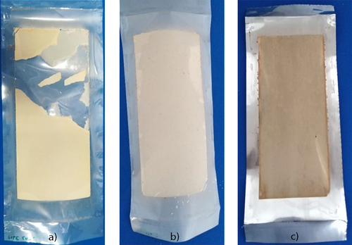
The strength of the adhesion forces between the scaling layer and the tested heat transfer films was assessed qualitatively by inspecting the degree of fouling layer adhesion at the end of the run. Images of the fouling layers for each heat transfer film are depicted in Fig. 5. It can be observed that the fouling layer is fragile, brittle, detachable, and non-adhering to the pure PEEK polymer film, whereas the fouling layer adheres very strongly to PEEK-Talc (Fig. 5b) and S.S. (Fig. 5c).
The results above confirmed that PEEK polymer films have the advantage of their applicability as a novel heat transfer material in seawater desalination plants, especially in MED units. The low adhesion force of mixed seawater scaling crystals to the PEEK surface is considered as a distinctive property that makes this material suitable for in-situ cleaning, without the need for high-cost cleaning, maintenance, shutdown, and anti-scaling chemicals. The cost of water production from seawater could be dramatically decreased by applying PEEK as a replacement or coating of the currently existing traditional metallic materials.
4.2 Analysis of the Surface Characteristics
4.2.1 Surface Roughness
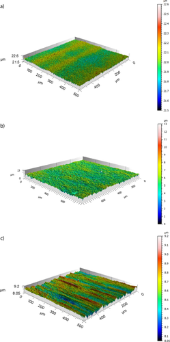
The adhesion/detachment characteristics of the investigated heat transfer films might correlate with their surface properties. The surface roughness and topographic structures of the investigated films were analyzed using the confocal microscope μsurf expert (NanoFocus AG, Oberhausen, Germany). The measured three-dimensional (3D) topographic images for PEEK, PEEK-Talc, and S.S. 1.4301 are illustrated in Figs. 6a–c, respectively. The roughness analysis (Tab. 2) and the 3D topographic images (Fig. 6) demonstrated that PEEK has the lowest roughness values and is distinguished by a homogeneous topography (Fig. 6a). On the other hand, PEEK-Talc (Fig. 6b) and S.S. (Fig. 6c) films are characterized by a significantly rougher surface.
In this work, it was found that the roughness parameters and the surface topography are the key characteristics of the surface that directly affect the adhesion forces of the scaling layer at the heat transfer surface. These properties of the PEEK film are of importance for developing PFHX for seawater desalination due to the fact that the adhesion of fouling deposits is usually very low for such a surface roughness.
|
Film |
PEEK |
PEEK-Talc |
S.S. 1.4301 |
|---|---|---|---|
|
Sp [μm] |
0.69 |
4.66 |
1.02 |
|
Sv [μm] |
0.88 |
5.19 |
0.79 |
|
Sq [μm] |
0.08 |
0.74 |
0.16 |
|
Sa [μm] |
0.06 |
0.59 |
0.13 |
4.2.2 Contact Angle, Surface Free Energy, and Polarity
The contact angles, surface energies, and polarities of the investigated films have been studied previously in detail and are listed in Tab. 3.
|
Film |
PEEK |
PEEK-Talc |
S.S. 1.4301 |
|---|---|---|---|
|
Surface free energy [mN m−1] |
40.57 |
43.55 |
32.38 |
|
Polarity [%] |
10.4 |
10.47 |
12.29 |
|
Contact angle (water) [°] |
77.19 |
82.75 |
83.71 |
As can be observed from Tabs. 2 and 3, the PEEK polymer film has the lowest value of the arithmetic average roughness and the lowest value of polarity. These surface properties are related to the smaller adhesion strength of the scale layer with a pure PEEK film. In addition, it can be predicted that the PEEK film has a relatively low contact angle compared to the other films. For pure PEEK, the surface energy lies between the two other materials investigated. Due to the very similar energetic properties of PEEK and PEEK-Talc, the difference in susceptibility to fouling must lie in the significantly higher roughness of PEEK-Talc.
4.3 Evaluation of the PEEK Polymer Film for Seawater Desalination
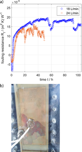
In order to evaluate the application of the PEEK polymer film as heat transfer surface material in seawater desalination, the performance of these films was investigated under different operating conditions. Fig. 7a shows the measured fouling resistance over 100 h and Fig. 7b displays the fouling layer formed during the same experiment. It can be envisaged from Fig. 7a that the induction time is less than 5 h, which is considered as a short induction time. According to Eq. 3, the short induction time of the PEEK polymer film can be attributed to its high values of surface free energy (Tab. 3) and the high level of supersaturation with respect to the scaling compounds in seawater. However, the more distinct property for the thermal seawater desalination industry is that the fouling layer does not adhere to the surface and that part of the fouling layer is detached by the flowing seawater (Fig. 7b). This can be clearly observed in Fig. 7a, where a periodic drop in fouling resistance takes place during the 100-h run. These results prove the advantage of the PEEK polymer film enabling in-situ cleaning.
4.4 Evaluation of the PEEK Polymer Film: Influence of the Flow Rate
The operational condition affecting the in-situ cleanability and adhering characteristics of the PEEK polymer film is based on the hydrodynamic conditions. Fig. 7a describes the influence of the flow rate on the scale layer formation. It can be predicted that both the fouling resistance and the asymptotic values are decreased by increasing the flow velocity. Also, the asymptotic fouling resistance value is very sensitive to the flow velocity, especially at higher flow velocities. From the results shown in Fig. 7a, it is clear that an increase of the velocity will increase the removal rate of the fouling layer, thus reducing the thickness of the deposited fouling. The frequent drop in fouling resistance at the higher flow rate of 24 L min−1 (Fig. 7a) indicates a recurrent removal of the fouling layer, which is more frequent and intensive than in the case of a lower flow rate. This result is considered as an important characteristic of the PEEK polymer film because of the possibility of preventing or controlling the fouling layer formation by variation of the hydrodynamic conditions in the PFHX.
There are many studies reported in the literature about the influence of the flow rate on the scale layer formation. Rodriguez and Smith 30 demonstrated that fouling removal mostly depended on the flow velocity. Abd-Elhady et al. 31 validated that the fouling removal is related to the impact speed or the contact time of the incident particles. Polley et al. 32 proved that the fouling removal rate is proportional to the 0.8th power of the Reynolds number.
It can be predicted from Eq. 5 that the removal of fouling depends on both the velocity and the adhesion force of the fouling layer to the surface. The low adhesion force of the fouling layer is an important distinctive property of PEEK films, enabling removal of the fouling layer at elevated flow rates.
4.5 Evaluation of the PEEK Polymer Film: Influence of the Seawater Salinity
The influence of the seawater salinity (i.e. the salt concentration) on the scaling behavior of the PEEK polymer film was measured. Fig. 8 shows the measured fouling resistances over time for seawater salinities of 35 and 45 g L−1. The surface temperature, bulk temperature, and flow rate are kept constant. Fig. 8B illustrates a faster growth rate of the scale layer at higher seawater salinity after the induction time (negative fouling resistance range). At both salinities, it can be observed that the fouling layer is removable and easily detachable, which supports the statements in Sect. 4.1.
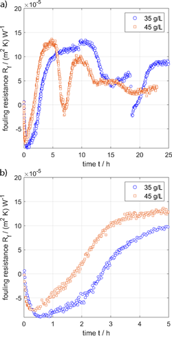
The salinity affects the concentration of the scaling materials in seawater and thus the supersaturation (S), which is the driving force for the initiation of scaling (nucleation) and the growth in the next stage. Seawater of higher salinities has a higher supersaturation (S) with respect to scaling minerals. Theoretically, according to Eq. 3, the induction period decreases at higher supersaturation (higher salinity). On the other hand, it is clear from Eq. 6 that the rate of mass deposition increases at higher supersaturations (S). Both effects could be demonstrated experimentally, which is shown in Fig. 8B in particular. The induction phase shortens and the growth rate increases with higher salinity. In the case of pure PEEK, however, the salinity does not seem to have any influence on the asymptotic or maximum fouling resistance, which is characterized by the low adhesive forces of the coverings.
5 Conclusions
This study investigates the advantages of applying polymer film heat transfer surfaces as novel materials for seawater desalination. The pure PEEK polymer film was found to be an appropriate material for operation in a seawater environment, especially in MED units. This polymer film is characterized by low forces of adhesion to the scaling layer. The results obtained demonstrated that the formation or growth of the scale layer can be prevented by easy removal of the scale layer through changing the hydrodynamic conditions around the scale layer, which is easily detachable. Periodic pulsed flow or a simple washing process can be applied in situ to remove the scale layer. Consequently, applying a PEEK polymer material in seawater desalination as alternative to the traditionally used metallic surfaces or as coating will effectively reduce the costs of cleaning and maintenance while avoiding shutdown procedures. In addition, the cost of anti-scaling chemicals will be completely cancelled and therefore the overall cost of seawater desalination will be dramatically reduced.
Acknowledgements
The authors wish to appreciatively acknowledge the funding from the Deutsche Forschungsgemeinschaft (DFG) to support the cooperation with Jordan in the frame of the DFG-HCST agreement, Grant Number 432741196.
The authors have declared no conflict of interest.
Symbols used
-
- As [m2]
-
heat transfer surface area
-
- B [m2]
-
fluid flow cross-sectional area
-
- Cb [kgparticles kgSW−1]
-
concentration of fouling (particles) in the bulk of the fluid
-
- F [L min−1]
-
flow rate
-
- K [s−1]
-
proportionality constant in Eq. 5
-
- k1 [–]
-
proportionality constant in Eq. 6
-
- md [kg−1m−2s−1]
-
deposition rate
-
- mr [kg m−2s−1]
-
rate of removal
-
- Rf [m2K W−1]
-
fouling resistance
-
- SA [g L−1]
-
seawater salinity
-
- S [–]
-
supersaturation
-
- Sp [μm]
-
maximum height of the peaks
-
- Sv [μm]
-
maximum depth of the valleys
-
- Sq [μm]
-
mean square root roughness
-
- Sa [μm]
-
arithmetic average height
-
- St [–]
-
stickability
-
- T [K]
-
absolute surface temperature
-
- TB [°C]
-
seawater bulk temperature
-
- TS [°C]
-
hot surface temperature
-
- U0 [W m−2K−1]
-
overall heat transfer coefficient of the clean surface
-
- Uf [W m−2K−1]
-
overall heat transfer coefficient of the fouled surface
-
- u [m s−1]
-
velocity
-
- xf [m]
-
thickness of the fouling layer
Greek symbols
-
- φ [N m−2]
-
force of adhesion to the surface
-
- ρf [kg m−3]
-
density of the fouling layer
-
- ρ [kg m−3]
-
density of the seawater
-
- σ [J m−2]
-
surface free energy
-
- θ [°]
-
contact angle of the crystals on the surface
-
- τ [s]
-
induction time
Subscripts
-
- b
-
fouling particles in the bulk
-
- B
-
bulk
-
- d
-
deposition
-
- f
-
fouling
-
- r
-
removal
-
- s
-
surface
-
- 0
-
clean surface
Abbreviations
-
- MED
-
multiple-effect distiller
-
- MSF
-
multi-stage flash
-
- PEEK
-
poly(ether ether ketone)
-
- PFHX
-
polymer film heat exchanger
-
- S.S.
-
stainless steel


