Energy-Efficient Hydrogen Generation via Peroxide-Mediated Electrocatalytic Pathways
Graphical Abstract
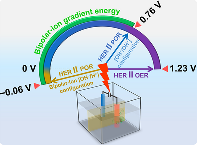
The advantages of peroxide redox chemistry are explored for green hydrogen production. Peroxide redox electrocatalysts enable efficient and selective peroxide production and oxidation, facilitating on-site hydrogen generation while achieving a nearly 50% reduction in applied potential compared to conventional water-splitting methods. An integrated bipolar-ion gradient system further reduces energy requirements to nearly one-third of traditional electrolysis.
Abstract
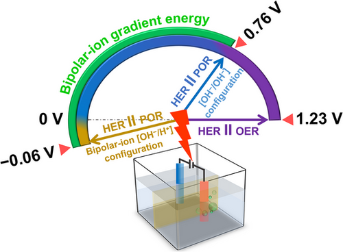
Hydrogen (H2) production through water electrolysis is a promising route for sustainable energy storage. However, conventional water electrolysis faces several challenges, such as large thermodynamic potential gaps and sluggish oxygen evolution kinetics, which lead to high electricity consumption and limitations in H2 storage and transportation. A promising approach to overcoming these hurdles is hybrid water electrolysis, which integrates alternative, thermodynamically favorable reactions at the anode to enhance efficiency. In this study, we explore how peroxide redox electrocatalysis can address critical barriers in sustainable H2 production, storage, and transport. By leveraging a cost-effective and highly efficient peroxide redox electrocatalyst, we demonstrate various electrolysis configurations that significantly reduce the required cell voltage—from the standard 1.23 V down to −0.06 V, highlighting its potential for scalable and economically viable electrolysis methodologies for H2 production.
Introduction
Hydrogen (H2) is a carbon-free alternative energy source with many advantages, including environmental friendliness, high energy density of 142.35 MJ kg−1, and zero-pollution emissions, making it a promising candidate as a future energy source.[1-4] Among the various methods of H2 production, water electrolysis stands out as a green approach that offers both high purity and sustainability.[5-8] However, several challenges are still associated with hydrogen production and usage.
Commercial water electrolyzers have high electricity demand, typically ranging from 4.3 to 5.73 kWh to produce 1 m3 of H2 (for an alkaline electrolyzer configuration), operating at cell voltages of 1.8–2.4 V and practical current densities of 300–500 mA cm−2.[9-12] This high voltage results from the theoretical thermodynamic potential—1.23 V versus (vs.) reversible hydrogen electrode (RHE)—and additional overpotentials, mainly due to the sluggish oxygen evolution reaction (OER).[13-15] Moreover, the storage and transportation of hydrogen remain a significant challenge due to hydrogen's low density and the need to apply high energy to compress it.[16-20] Additionally, there is limited or nonexistent infrastructure for H2 transformation and transportation by truck or ship due to high flammability and requirements for high-pressure tanks.[18-20]
Hydrogen peroxide offers new opportunities to facilitate H2 production, transportation, and storage. Recent studies have highlighted acidic-based peroxide electrolyzers for H2 production.[21, 22] However, the present regeneration architecture achieves hydrogen peroxide yields lower than 65% via the two-electron oxygen reduction reaction (2e− ORR),[22] limiting the overall efficiency of this approach under these conditions.[21, 22]
Replacing the OER with thermodynamically more favorable electro-oxidation reactions offers a new strategy for energy-efficient hydrogen production by integrating hybrid water-splitting technology.[23-26] Among the available options, the faster kinetics of the peroxide oxidation reaction (POR: OH− + HO2− → O2 + H2O + 2e−, 0.76 V vs. RHE)[27-29] holds great promise, and it enables H2 production at much lower voltages than OER. In this configuration, H2 is produced at the cathode (HER), and hydrogen peroxide is oxidized to O2 at the anode (i.e., POR). Moreover, the peroxide can act as a hydrogen carrier molecule, utilizing renewable energy sources as the energy input for the production and regeneration processes. Notably, this type of on-site regenerative approach is currently limited in other hybrid electrolyzers, such as hydrazine- or alcohol-based systems, due to their high energy demands.[23-26] In contrast, hydrogen peroxide offers a significant advantage by eliminating challenges associated with storing and transporting hydrogen or other hydrogen carrier molecules. This offers a complementary energy-saving pathway, specifically tailored for on-demand hydrogen generation in energy-constrained environments.
Here, we show how hydrogen peroxide can facilitate critical issues in sustainable H2 production, storage, and transportation. By utilizing a low-cost, efficient, and durable hydrogen peroxide bifunctional catalyst, we demonstrate three different configurations for H2 production, which enable the theoretical reduction of the cell voltage from 1.23 V up to −0.06 V (Scheme 1): i) an alkaline peroxide electrolyzer (APE), where POR replaces OER, resulting in significantly lower cell potentials, e.g., a current density of 50 mA cm−2 is achieved at 1.0 V, compared to 2.2 V in traditional water-splitting electrolyzers; ii) using the same cell for hydrogen peroxide generation followed by its consumption and hydrogen production, enabling a self-sustainable system, which can produce hydrogen on demand; and iii) a bipolar peroxide electrolyzer (BPE) that is achieved by integration of an electrochemical neutralization strategy in which the HER and POR occur in acidic and alkaline electrolytes, respectively, enabling low cell voltages. Specifically, a current density of 100 mA cm−2 is reached at ∼0.48 V—nearly three times lower than using APE.
Results and Discussion
Ni/NiOx-based electrocatalysts for the peroxide oxidation reaction (POR) were synthesized via a molten-state reaction in pyrene (Py) in accordance with our previous publication[30] (please refer to the Supporting Information for more details about the synthetic method). Full characterizations of the synthesized electrocatalysts, Nix/Py (where x represents the wt. % of Ni in the precursors), are provided in the Supporting Information, Figures S1–S4 and Notes S1–S2. At low Ni2+:Py ratios in the precursor, the NiOx phase is more prominent. Eventually, at nickel loading of x ≥ 30 wt. %, no detectable NiOx signal remains in X-ray diffraction (XRD) analysis. All the examined catalysts exhibit some degree of graphitic diffraction, indicating the formation of crystalline sp2 carbon during pyrolysis.[30]
To reveal the best POR and 2e− ORR electrocatalyst, we scanned Ni10‒40/Py compositions. POR studies via cyclic voltammetry (CV) curves—using rotating disc electrode (RDE) experiments at 1600 rpm with 1 M KOH and 0.01 M of hydrogen peroxide—Figure S5a, show Ni20/Py as the optimal electrocatalyst with J = 7.5 mA cm−2 at 0.94 V (close to the theoretical voltage of 0.76 V vs. RHE[27-29]). Therefore, all studies reported henceforth are performed using a Ni20/Py electrocatalyst. The current density rapidly increased upon utilization of higher HO2− concentrations (Figure 1a); in 1 M KOH and 0.05 M HO2−, high current densities of ∼50 mA cm−2 are obtained at low overpotentials of 0.2 V (Figure 1a). For comparison, OER with the same Ni20/Py catalyst electrode requires ∼2 times higher potential (∼1.87 V vs. RHE) for reaching the same current density level in 1 M KOH (Figure S5b).
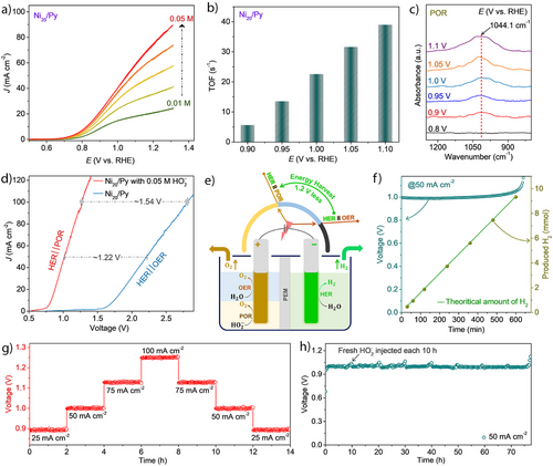
RDE measurements (Figure S5c) and Levich plot (Equation S3) analysis (Figure S5d) indicate high HO2− to O2 (OH− + HO2− / O2 + H2O + 2e−) selectivity with the number of electrons transferred close to 2 (Figure S5d and Note S3; Supporting Information). The turnover frequency (TOF) values of the catalysts for POR at different potentials indicate fast kinetics (Figures 1b and S6, Supporting Section 5.1, and Equations S4, S5; Supporting Information) with a high TOF value of ∼39 s−1 at 1.1 V versus RHE.
In situ attenuated total reflection Fourier-transform infrared (ATR‒FTIR; Scheme S1) spectroelectrochemical analysis (Figure 1c) reveals an absorption band of ∼1044.1 cm−1 under potentials of 0.8 to 1.1 V versus RHE, which corresponds to the O─O stretching mode of adsorbed hydroperoxyl species (OOHad) on the active Ni3+ sites of the Ni20/Py catalyst.[31, 32] This feature provides crucial insights into the mechanism of the associative 2e− POR pathway (Equations S6, S7, Supporting Section 5.2; Supporting Information) and contributes to the overall stability of the catalyst during the process. A DFT (density functional theory) study further supports the formation of OOH on the Ni20/Py surface, which is associated with a significant energy gain of 1.6 eV. This results in a strong driving force for this critical step in the POR mechanism (see Supporting Section 5.3 and Figures S7–S9; Supporting Information).
The rate profile of POR of Ni20/Py was measured at potentials ranging from 0.9 V to 1.2 V versus RHE in 1 M KOH with 0.05 M HO2−. The current density is enhanced at high oxidation potentials, e.g., J ∼80 mA cm−2 was achieved at E = 1.2 V versus RHE; these activities retain even after recycling with different applied potentials, as shown in Figure S10a. Furthermore, the E–t curve of the Ni20/Py electrode at 50 mA cm−2 in 1 M KOH with 0.05 M HO2− exhibits a low voltage of ∼1.0 V versus RHE over 50 h (Figure S10b), implying good stability, high catalytic activity, and selectivity (> 96% J retention after 50 h).
At the next step, we assembled a 3-electrode (Figure S11) setup using 1 M KOH as the electrolyte with and without the addition of 0.05 M HO2−, measuring HER || POR and HER || OER, achieving voltages of 0.94 V versus RHE and 1.87 V versus RHE at 10 mA cm−2, respectively. To demonstrate the feasibility of using POR for sustainable H2 fuel production, we built an alkaline peroxide electrolyzer (APE) setup with a zero-gap configuration (Figure S12, Supporting Section 6). At 100 mA cm−2 (Figure 1d), the difference in the cell voltages between the alkaline electrolyzer (AE) (∼2.8 V) and APE (∼1.26 V) is ∼1.54 V highlights the significant advantage of POR over OER in the anodic compartment (Figure 1e). Increasing the cell voltage from 0.77 to 1.26 V results in a monotonic current density increase up to ca. 100 mA cm−2.
The amount of H2 produced in the APE prototype was tested at 50 mA cm−2 in 2 M KOH with 0.2 M HO2− using the water displacement technique (Figure 1f). The volume change was measured every 120 min for 10 h. The produced H2 amount is close to 9.2 mmol cm−2 of the theoretically predicted quantity for each measurement interval, indicating a Faradaic efficiency of about 98.4% (Calculation S1). The cell voltage maintains a stable value of ∼1 V for most of the experiment. After 600 min, the POR is almost complete due to peroxide consumption, resulting in a sharp voltage increase as the OER replaces the POR, Figure 1f. The APE prototype demonstrates an impressive voltage efficiency (the ratio between theoretical and actual voltage), over 90% at a current density of 10 mA cm−2. Even at a significantly higher current density of 100 mA cm−2, the voltage efficiency remains at around 60%, showcasing strong energy utilization performance compared to the traditional prototype for H2 fuel production, Figure S13 and Table S1.
Stability tests were performed at J = 25, 50, 75, and 100 mA cm−2 and reduced back to 25 mA cm−2 using 25 mA cm−2 steps, where the cell was held for 2 h at different applied current density step (Figure 1g). The current density was recovered to its initial value, and at each step, the cell voltage did not strip, demonstrating the good stability of the catalyst. Long-term stability (Figure 1h) measurement further emphasizes the robustness of Ni20/Py in a highly oxidative environment (0.2 M HO2− in 2 M KOH). At a steady current density of 50 mA cm−2, with fresh HO2− injection every ∼10 h, the Ni20/Py retains its performance for over 75 h, with a steady cell voltage of ∼1.0 V. The strategy outlined here demonstrates that replacing the slow OER with fast POR at the anodic part can result in more efficient hydrogen production with high voltage efficiency.
Ni20/Py demonstrates dual activity as an efficient electrocatalyst for POR and 2e− ORR to hydrogen peroxide (HO2‒).[33] Rotating-ring disk electrode (RRDE) tests indicate that Ni20/Py offers high Faradaic efficiencies exceeding 95% over a wide potential range (0.75–0.2 V), high selectivity for HO2−, and excellent stability (Figures S14–S16, Supporting Section 7, Equations S9, S10, and Note S4; Supporting Information). The highest TOF value of ∼3.1 s−1 was obtained for Ni20/Py at a potential of 0.5 V versus RHE (Figure S17a). These properties make it a highly active and selective electrocatalyst for practical HO2‒ synthesis. In situ FTIR studies confirm the existence of OOHad as an intermediate,[31, 32] verifying the associative 2e− ORR pathway without further reduction of PRR (Figure S17b and detailed discussion in Note S5, Supporting Information).
Next, we measured in a commercial setup the HO2‒ production at a three-phase boundary between the electrolyte, O2(g), and the solid electrocatalyst, deposited on a gas diffusion layer (GDL), i.e., the surface of Ni20/Py@GDL, Figure 2a (see further details in the Supporting Information: Supporting Sections 8–9 and Figures S18, S19). The HO2‒ production rate varies with current density, Figure 2b, with a maximum production rate of 4.5 ± 0.2 mol gcat−1 h−1 at 0.3 V versus RHE, ∼130 mA cm−2 (Figures 2b, and S20a and Note S6, Supporting Information). This rate showcases the high activity of Ni20/Py@GDL for electrocatalytic hydrogen peroxide production (Table S2, Supporting Information). The Ni20/Py@GDL exhibits excellent stability at a constant voltage of 0.6 V versus RHE (ca. −44 mA cm−2) (Figure 2c). Over a 120 h test period, the HO2‒ concentration increased linearly, with a total production of 73.2 mmol HO2‒ and a linear production rate of 0.73 ± 0.03 mmol h−1, maintaining an average Faradaic efficiency of over 92% (Figures 2c and S20b, Supporting Information). The high selectivity stems from the suppressed sequential reduction of HO2− to OH‒ (i.e., the peroxide reduction reaction, PRR), enabling high selectivity over a large voltage window (0.15 to 0.79 V, Figure 2d). Self-decomposition analysis using LSV profiles and UV–vis absorbance reinforces Ni20/Py stability under alkaline conditions over 50 h with 0.05 M HO2−, Figure S21. Additionally, a custom two-electrode flow cell was tested, using Ni20/Py as the cathode and Ni foam as the anode. The LSV results, shown in Figure S22, demonstrate that the constructed system can deliver a high current density of approximately −133 mA cm−2 at a cell voltage of around −1.3 V.
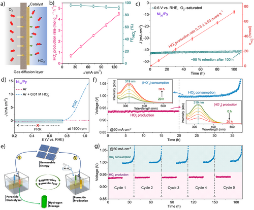
Our results imply that Ni20/Py acts as an excellent bifunctional catalyst for both POR and ORR at high current densities. This dual functionality enables us to divide the water-splitting process to i) an on-site generation of HO2‒ in electrolysis mode, and ii) production of H2 fuel without the need for complex hydrogen transfer infrastructure upon demand. The HO2− serves as the fuel for the APE, enabling a self-sustaining system that can regenerate its fuel over the Ni20/Py catalyst and even eliminates the need for external hydrogen peroxide transportation, Figure 2e.
A proof-of-concept experiment demonstrates multiple cycles of first generating HO2‒ and then consuming it for hydrogen production as a second stage. In situ UV–vis colorimetric analysis confirmed the production and consumption of HO2‒ in their respective compartments during the regenerative cycle, inset of Figures 2f and S23a,b (Supporting Section 10). In the first cycle, we produced 16.63 mmol (FE, 89.12%) of HO2‒ over 20 h, Figure 2f and Calculation S2a (Supporting Information). After switching the counter electrode from a Ni foam to a Pt mesh, the generated HO2‒ of the previous cycle was consumed, ∼16.05 mmol (FE, 96.68%), over 17.8 h (total 37.8 h of analysis), Figure 2f and Calculation S2b (Supporting Information). During the POR, the cell voltage stabilized at ∼1 V; when the POR was completed (after ∼17.8 h), the applied voltage shifted entirely to the OER. Additional O2 quantification gave 392 mL, equivalent to ∼16.03 mmol of generated O2 with a FE of 96.6% during HO2‒ consumptions over 17.8 h (Figure S23c and Calculation S2c; Supporting Information).
The evaluated overall energy efficiency of the regenerative system is 85.9% with parasitic losses of 14.1% (Calculation S2d, indicating a highly repeatable regenerative performance over multiple cycles using the Ni20/Py catalyst (Figure 2g). The analysis of the bifunctional Ni20/Py catalyst over a carbon electrode after multiple regenerative (HO2‒ production/consumption) cycles (∼189 h) shows no significant morphological or structural changes (see Figures S24, S25 and the detailed discussion thereafter, Supporting Information). To reduce the necessary input electricity while maintaining or increasing the current density, we utilized the bipolar-ion energy [OH‒/H+] for a more efficient hydrogen fuel production. The energy released from the neutralization of bipolar-ions [OH‒/H+] has been extensively studied for boosting the performance of various energy systems.[34-38] More importantly, in the context of H2 production, the integrated electrochemical neutralization device can be sustainably operated using acidic and alkaline industrial waste streams, serving as a virtually cost-free electrolyte source.[34-38] Thermodynamic calculations (Supporting Section 11 and Calculation S3, Supporting Information) indicate that approximately 0.828 V of electrical energy can be harvested from bipolar-ion gradients at room temperature when the reaction is driven electrochemically.
Since the HER is a pH-dependent electrochemical process, the LSV profile (Figure S26a) showed a negative voltage shift with increasing alkalinity, with a negative slope of 60 mV per pH unit in the Pourbaix diagram (Figure S26b). This suggests that an identical number of electrons and protons are transferred during the reaction, and the onset of voltage difference is almost 0.8 V (Figure S26c). HER activity analysis (Figure S26d,e) confirms that Pt-based electrocatalysts exhibit better HER performance in acidic media.[39, 40]
Furthermore, to demonstrate that the “hidden” electrical driving force from OH‒/H+ (bipolar-ion) gradients can be harvested for electricity-efficient peroxide electrolyzer setups for hydrogen production, it is crucial to note that bias-free hydrogen production can be achieved in this configuration, as illustrated in Scheme 1. Of note is the potential beneficial environmental impact of utilizing acidic and alkaline waste streams in a practical device, thus harnessing the exothermic neutralization reaction of corrosive and toxic reactants to produce clean hydrogen.[35-37] The bipolar-ion peroxide electrolyzer (BPE) setup consists of an anodic half-cell with a pH ∼14 (2 M KOH) solution and a cathodic half-cell containing a pH ∼0 (1 M H2SO4) solution, separated by an ionic conducting membrane (see Supporting Section 11.1 and Figure S27). As a comparison, a symmetric-ion electrolyte [OH‒/OH‒] without the bipolar-ion gradient is configured with both compartments filled with an alkaline electrolyte (2 M KOH).
In the BPE configuration, an electrical voltage is applied between a Ti-coated platinum mesh electrode in the acidic catholyte and a Ni20/Py-based electrode in the alkaline anolyte. These electrodes facilitate the HER at the cathode and POR at the anode, respectively (Supporting Section 11.1 and Figure S27). The HER efficiency is notably enhanced by the pH gradient in the bipolar-ion configuration, with HER occurring on the Pt-based electrocatalyst in the acidic half-cell. These results suggest that the bipolar-ion gradient can be effectively harnessed as an electromotive force (emf). The Gibbs free energy change of neutralization (ΔGneutralization) and the available emf (potential, E) depend on the ΔpH between the two electrolytes, as shown in Figure S28a. As ΔpH increases, ΔGneutralization becomes more negative, manifesting in a more positive E (Figure S28a, Calculation S4, Note S7, and Equations S12, S13; Supporting Information). As shown in Figure 3a, the voltage for the overall reaction is significantly lower utilizing the bipolar-ion gradient compared to the symmetric electrolyte configuration (0.06 V vs. 0.94 V at 10 mA cm−2) and a difference of 0.88 V, due to the bipolar-ion gradient energy, is observed (Calculation S5, Equations S14, S15; Supporting Information).
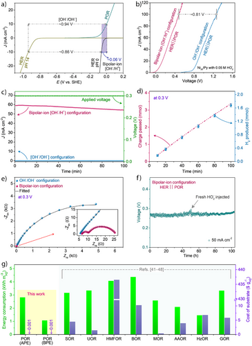
To experimentally evaluate the emf contribution derived from the bipolar-ion gradient, we have employed two identical Pt electrodes in asymmetric electrolytes with bipolar-ion gradient as well as in a symmetric electrolyte without a pH gradient [OH‒/OH‒], Figure S28b. The emf was ∼0.8 V in the asymmetric electrolyte with bipolar-ion pH gradients, which is close to the thermodynamic potential for a bipolar-ion reaction at room temperature (Calculation S3). It corroborates that the bipolar-ion reaction energy can be harvested as electromotive force in a pH gradient configuration to aid efficient H2 production. LSV profiles for the BPE configuration, Figure 3b, show very low onset potential after introducing HO2− in the electrolyte due to the POR (Figure S28c). At the same time, a voltage difference of nearly 1.3 V at 100 mA cm−2 is obtained when using OER instead. The onset potential for BPE with bipolar-ion gradient starts nearly at ‒0.03 V, whereas it is 0.77 V for the APE configuration, Figure 3b. Notably, using the BPE enables a current density of 100 mA cm−2 at 0.48 V, while in an APE configuration (without the bipolar-ion gradient) the required voltage is nearly 1.29 V (Figure 3b). At a low voltage of 0.3 V, a high current density was obtained in the BPE configuration, Figure 3c. The produced hydrogen is quantified at the cathodic side by the water displacement technique, showing FE ∼98.3%, Figure 3d (see Calculation S6). Although the current density notably decreases with the progress of the reaction (Figure 3c), the total charge passed through the system increases with time; hence, the total produced H2 matches the total charge passed, Figure 3d. Electrochemical impedance spectroscopy (EIS) analysis at 0.3 V, reveals a significant reduction in charge transfer resistance (Rct) and faster kinetics for the BPE configuration compared to the APE configuration, Figure 3e (see fitting parameters in Table S3 and Note S8, Supporting Information).
In the BPE prototype using a bipolar-ion gradient cell, the concentration changes of H+ and OH‒ ions in both half-cells were monitored (detailed explanations provided in Note S9, Supporting Information). The results indicate only a marginal change in the concentrations of H+ and OH‒ ions after operation for 100 min. The amount of H2 released at the cathodic compartment corresponded to the changes in H+ ion concentration in the cathodic half-cell (Figure S29). It is important to note that when the cell was kept under idle conditions, the changes in H+ and OH‒ concentrations were negligible in both half-cells over 30 h (Figure S30). This indicates that the bipolar-ion gradient acts as the driving force in the overall reaction. The rate profiles of BPE were performed at different current densities ranging from 25 to 150 mA cm−2.
A high and stable current density rate of 150 mA cm−2 was achieved at a low applied voltage of ∼0.7 V in the BPE configuration, Figure S31, suggesting that the BPE can perform efficiently toward H2 production at low voltages. The current densities were cycled back from 150 to 25 mA cm−2, showing the same voltages (Figure S31), highlighting the excellent stability of the electrocatalyst. The flow-type BPE cell can continuously produce hydrogen for over 100 h at J = 50 mA cm−2 and a cell voltage of 0.27 V (Figure 3f), using active electrolytes maintained at 2 M H2SO4 (catholyte) and 4 M KOH (anolyte) with 0.5 M HO2−; the HO2− is injected over a 50 h period, which extends system durability under practical conditions. The overall energy efficiency of the BPE system reaches 90.7%, demonstrating that the proposed strategy offers highly effective electrical efficiency for H2 production (Calculation S7). Postoperation characterization shows no noticeable changes in the structural and morphological characteristics of Ni20/Py coated on a carbon electrode (Figures S32, S33), confirming the catalyst's stability. The BPE approach, coupled with POR, offers a more efficient pathway for H2 fuel generation at higher current densities.
The integration of a bipolar-ion gradient into the BPE configuration has the potential to replace traditional electrolysis, which typically consumes nearly three times the electricity, making H2 fuel production more energy-efficient and cost-effective.
The energy consumption of the proposed bipolar system requires only 1.01 kWh of energy to produce 1 m3 of H₂ (detailed calculations are provided in Supporting Section 12, Calculations S8, S9, and Table S4; Supporting Information), corresponding to a production cost of ca. 0.03 $ m−3 H2, assuming the use of acidic and alkaline waste streams as feedstock. This reflects improved energy efficiency compared to most reported systems (Figure 3g and Table S5).[41-49]
It is also important to note that the production cost of HO2− via the 2e− ORR pathway is minimal—approximately 0.034 kWh g−1 of produced H2, equivalent to 0.001 $ g−1 H2 (see Calculation S9). In comparison, many substrates used in conventional hybrid electrolyzers are nonrenewable and associated with significantly higher costs (Figure 3g).[41-48]
Moreover, a preliminary techno–economic analysis (TEA),[37] a comparison of plant-gate levelized hydrogen production costs shows that the BPE system offers a lower cost per ton of H2 relative to other hybrid electrolyzer technologies (see Calculation S10, Table S6, Note S10, and Figure S34; Supporting Information). Our findings demonstrate that low-cost, regenerative, and renewable substrates for peroxide-mediated H2 production offer a promising pathway toward scalable, sustainable hydrogen fuel generation, with potential applications that eliminate the need for hydrogen transformation and storage infrastructure.
Conclusion
We have demonstrated the advantages of hydrogen peroxide chemistry for green hydrogen production. We show that using a bifunctional catalyst allows efficient and selective hydrogen peroxide production, which can be used for on-site hydrogen production at half the typical energy of conventional full electrolytic water-splitting. Moreover, the developed bifunctional catalyst enables direct hydrogen production using in situ-generated HO2−, eliminating the need for external H2O2 transport. This self-sustaining, regenerative process significantly reduces substrate costs to the order of 0.001 $ g−1 of H2 via the 2e− ORR pathway. The optimized catalyst demonstrates a superior hydrogen peroxide generation rate of 4.5 ± 0.2 mol gcat−1 h−1 while also serving as a POR catalyst, leading to high and stable hydrogen production on the cathodic side. We further exploit this concept using a bipolar-ion [OH‒/H+] gradient energy. As a result, a significantly lower potential is required to obtain high current densities, about three times lower than in traditional electrolysis. The proposed system requires an estimated energy of 1.01 kWh to produce 1 m3 of H2, demonstrating improved energy efficiency compared to most reported systems. Our findings establish hydrogen peroxide-mediated hydrogen production as a promising pathway for scalable and sustainable H2 fuel generation, with potential applications that eliminate the need for hydrogen transformation, storage, and transportation infrastructure. This work represents a step forward in developing energy-efficient on-site hydrogen production technologies.
Acknowledgements
This research was partially supported by the Pazy Research Foundation (Grant No. 656-2025) and also received partial funding from the JNF Canada Inc. award. A.R.K acknowledges financial assistance from the Kreitman scholarship (Ben-Gurion University of the Negev, Israel). The authors acknowledge Gabriel Mark for assistance with XPS and XRD analysis, Dr. Alexander Upcher for TEM, and Prof. Idan Hod for allowing us to operate the in situ FTIR spectroscopy instrument.
Conflict of Interests
The authors declare no conflict of interest.
Open Research
Data Availability Statement
The data that support the findings of this study are available from the corresponding author upon reasonable request.


