Intermediate Color Emission via Nanographenes with Organic Fluorophores
Graphical Abstract
Nanographenes (NGs) produced by top-down methods carry multiple functional groups. We utilized this aspect for the reproduction of purple light by adding red- and blue-light emitting fluorophores. Based on our results, NGs can be utilized as carriers of fluorophores capable of generating intermediate colors of light.
Abstract
Photoluminescence (PL) color can be tuned by mixing fluorophores emitting the three primary colors in an appropriate ratio. When color tuning is achieved on a single substrate, we can simplify device structures. We demonstrated that nanographenes (NGs), which are graphene fragments with a size of tens of nanometers, could be utilized as carriers of fluorophores. The addition of red- and blue-light-emitting fluorophores on the edge successfully reproduced the purple light. The relative PL intensities of the fluorophores could be regulated by the excitation wavelength, enabling multicolor emission between blue and red light. Owing to the triphenylamine units of the fluorophores, the NGs showed PL enhancement due to aggregation. This characteristic was valuable for the fabrication of solid polymer materials. Specifically, the functionalized NGs can be dispersed into polyvinylidene difluoride. The resultant polymer films emitted red, blue, and purple color. Our study demonstrated the potential applicability of NGs for fluorophore carriers capable of reproducing intermediate colors of light.
Introduction
The generation of the desired color of light requires fine tuning of electronic states and sometimes faces difficulty. For example, a purple light emission requires a large energy gap. Reported examples are inorganic light emitting diodes composed of group III nitrides and metal oxides,1 while the number of organic fluorophores emitting purple light is limited.2 An alternative procedure is to mix fluorophores emitting distinct colors, such as the three primary colors, to reproduce the desired color of light (Figure 1a).3-5 The aforementioned purple light can in principle be reproduced by mixing red- and blue-light emitting fluorophores. Although this procedure is straightforward, several problems can occur when device fabrication is considered. (1) A mixture of fluorophores may not form a homogeneous phase because they can have distinct affinities toward given media. This can cause color evenness. Hence, separation of the three primary colors has been employed in organic light emitting diodes.6 (2) Fluorophores, in particular those with π conjugated systems, can aggregate to cause photoluminescence (PL) quenching. When distinct kinds of fluorophores can be added into a single substrate, such as in a polymer backbone,7 without changing their PL colors, any color of light can be reproduced, and device structures can be simplified.
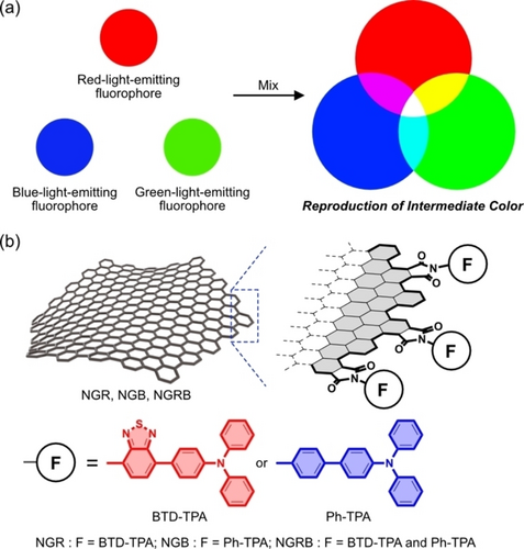
(a) Reproduction of an intermediate color of light by mixing three primary color emissions. (b) Schematic representation of NGs carrying BTD-TPA (NGR), Ph-TPA (NGB), and both (NGRB).
Nanographenes (NGs) are graphene8-11 fragments with a size of tens of nanometers produced by top-down methods and can be suitable scaffolds for the above goal.12, 13 NGs can be modified by one14-21 or distinct kinds of functional groups,22 and their relative loading ratio can be regulated by the reaction conditions.22 These properties are similar to the regulation of the concentrations of fluorophores in given media. Low PL quantum yields (QY) of NGs produced by a top-down method (0.1 %–1 %)23 do not significantly disturb the PL of the added fluorophores. Furthermore, the aggregation of NGs, which is inevitable for π conjugated systems, can be exploited for PL enhancement by using fluorophores with aggregation-induced emission enhancement (AIEE) character.24-27 Based on this background, NGs carrying benzothiadiazole-triphenyl (BTD-TPA) units and phenyl-triphenyl (Ph-TPA) units were designed as a proof-of-concept for the application of NGs as carriers of fluorophores capable of reproducing the intermediate color of light in solutions and in polymer films (Figure 1b). BTD-TPA and Ph-TPA emit red and blue light, respectively. The suitable loading ratio of the two fluorophores should reproduce purple light.
Herein, we report NGs carrying BTD-TPA (NGR), Ph-TPA (NGB), or both (NGRB). The addition of BTD-TPA and Ph-TPA into the edge successfully reproduced purple light, and these hybrid materials showed AIEE-like PL enhancement. Owing to their lipophilic nature, NGR, NGB, and NGRB can be dispersed into polyvinylidene difluoride (PVDF), enabling the fabrication of polymer films emitting red, blue, and purple light, respectively.
Results and Discussion
BTD-TPA and Ph-TPA were selected for a preliminary examination. The AIEE character of triphenylamine could avoid PL quenching when NGs were aggregated. Density functional theory (DFT) calculations28 predicted that the HOMOs and LUMOs of BTD-TPA and Ph-TPA were not significantly perturbed by NGs (Figures S13–S36 and Tables S2–S11 in the Supporting Information).
The synthesis of 4 a is shown in Scheme S1 in the Supporting Information. Compound 4 b is commercially available. Starting materials of all functionalized NGs were produced by the protocols reported previously.29-31 Acid-assisted oxidative cleavage of graphite (2 g) using conc. H2SO4 (180 mL) and 60 % HNO3 (60 mL) at 120 °C for 24 h to produce NGs. Then, NGs were neutralized and subjected to deionization and size separation with dialysis membranes (pore size=2 kDa) to remove NGs smaller than the pore size. The resulting NGs were treated with dialysis membranes (pore size=15 kDa) to remove NGs larger than the pore size. The aqueous solution of NGs leaked out from the membranes were concentrated to offer the product (NG) used in the synthesis of the functionalized NGs.
The installation of 4 a or 4 b into NG was achieved by the procedures shown in Scheme 1. Conversion of the carboxy groups on the edge into acid chlorides followed by the reaction of the resultant activated NG with 4 a or 4 b in a mixed solvent of DMF and triethylamine (1 : 1, v/v) at 80 °C for a couple of days provided crude products. Owing to their lipophilic nature, the products were purified by column chromatography on BioBeads S−X1 using THF as an eluent. The concentration of the THF solution followed by the addition of hexane caused precipitation of NGR or NGB as dark brown solids. NGRB was produced by similar procedures. The reaction of the activated NG with a mixture of 4 a and 4 b with a 1 : 0.43 molar ratio followed by purification produced NGRB. To assess the controllability of the relative loading ratio of the two fluorophores, NGRB-R (4 a : 4 b=1 : 0.11) and NGRB-B (4 a : 4 b=1 : 9.0) were also produced. The detailed synthetic procedures are compiled in the Supporting Information.
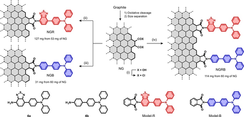
Synthesis of NGR, NGB, and NGRB. Reagents and conditions: (i) (COCl)2, cat. DMF, 60 °C, 4 days; (ii) 4 a, NG, DMF+Et3N (1 : 1, v/v), 80 °C, 4 days; (iii) 4 b, NG, DMF+Et3N (1 : 1, v/v), 80 °C, 4 days; (iv) 4 a, 4 b, NG, DMF+Et3N (1 : 1, v/v), 80 °C, 4 days. The basal planes of NG, NGR, NGB, and NGRB are drawn with a single line for clarity. The synthesis of NGRB-R and NGRB-B is stored in the Supporting Information.
For the characterization of the functionalized NGs, Model-R and Model-B, which are models of the BTD-TPA and Ph-TPA-installed armchair edge, were also synthesized. The reaction of phthaloyl chloride with 4 a and 4 b in DMF produced Model-R in 35 % yield and Model-B in 45 % yield, respectively.
Characterization was achieved by comparing the NMR and IR spectra of the functionalized NGs with those of Model-R and Model-B. The 1H NMR spectra of NGR and NGB showed broad signals, and their chemical shifts were consistent with those of the model compounds (Figure S8 in the Supporting Information). No signals corresponding to 4 a or 4 b were found in the 1H NMR spectra, confirming the elimination of the starting materials from solid NGR and NGB. This process is crucial for graphitic materials.32 The formation of the five-membered imides on the edge was confirmed by the weak and strong C=O stretching vibrations in the IR spectra (Figure S10 in the Supporting Information). The characterization of NGRB, NGRB-R, and NGRB-B was achieved by similar procedures. Their 1H NMR and IR spectra confirmed the addition of the fluorophores into the edge (Figures S11 and S12 in the Supporting Information), although the broadened 1H NMR spectra caused difficulty to estimate the loading ratio. Alternatively, the ratio of BTD-TPA and Ph-TPA was estimated by the absorption spectra to be 43 : 57 for NGRB, 77 : 23 for NGRB-R, and 3 : 97 for NGRB-B (Figure S9 in the Supporting Information). These ratios indicated that although the loading ratio can be regulated to a certain degree, Ph-TPA can be installed more easily than BTD-TPA. The electron-withdrawing nature of benzothiadiazole would lower the reactivity of BTD-TPA.
The absorption spectra of NGR and NGB in dichloromethane showed absorption bands at 309 and 454 nm for NGR and 314 and 364 nm for NGB assignable to the added fluorophores (black lines in Figure 2a-(i) and 2a-(ii)). The absorption bands were consistent with those of Model-R and Model-B (black broken lines in Figure 2a-(i) and 2a-(ii)), indicative of weak interactions between the fluorophore and the basal plane in the ground state, as indicated by the DFT calculations. This occurred due to the nearly orthogonal orientation of the fluorophores and the five-membered imides that hindered their electronic interactions (Figures S13–S16 in the Supporting Information).
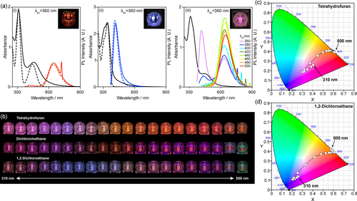
(a) UV-vis absorption and PL spectra (λex=360 nm) of (i) NGR (black solid line) and Model-R (black broken line), (ii) NGB (black solid line) and Model-B (black broken line), and (iii) NGRB (black solid line) in dichloromethane at 298 K. [NGR]=[NGB]=3.2×10⁻² mg mL−1. [NGRB]=4.2×10⁻² mg mL−1. [Model-R]=4.6×10⁻² mM. [Model-B]=7.8×10⁻² mM. The digital images in (i)–(iii) are the photoexcited NGR, NGB, and NGRB at 360 nm. (b) Change in the emission color of NGRB in THF, dichloromethane, and 1,2-dichloroethane by shifting the excitation wavelength from 310 nm to 500 nm with an interval of 10 nm. [NGRB]=1.0×10⁻² mg mL−1. (c) and (d) Change in the CIE 1931 color coordinates of the NGRB excited from 310 nm to 500 nm with an interval of 10 nm in (c) THF and (d) 1,2-dichloroethane.
The PL spectra showed that NGR and NGB showed PL bands with λmax=645 and 417 nm, respectively in dichloromethane (red and blue lines in Figure 2a-(i) and 2a-(ii)). The excitation spectra confirmed that the added fluorophores were major sources of the observed PL (Figure S37 in the Supporting Information). The PL bands were consistent with those of Model-R at λmax=643 nm and Model-B at λmax=412 nm (red and blue broken lines in Figure 2a-(i) and 2a-(ii)),33 indicating minimal effect on the PL wavelength after their addition into the edge. NGR and NGB showed red- and blue-light emission, respectively (inset in Figure 2a-(i) and 2a-(ii)). The PL intensity was affected by solvents and was stronger in THF than in dichloromethane and 1,2-dichloroethane. The absolute QYs of NGR and NGB in THF were 1.7 % (λex=420 nm) and 3.5 % (λex=340 nm), respectively. The absorption of the PL by the basal plane, the absorption band of which covers the visible region,30 would contribute to the low QYs.
Figure 2a-(iii) shows the absorption and PL spectra of NGRB in dichloromethane. Upon excitation at 360 nm (purple line), both BTD-TPA and Ph-TPA on the edge were excited and emitted blue (λmax=398 nm) and red (λmax=625 nm) light, respectively, reproducing purple light. The Commission Internationale de l'Eclairage (CIE) 1931 chromaticity diagram indicated that the color coordinate of NGRB at λex=360 nm was (x=0.31, y=0.21), which was between those of NGR (x=0.58, y=0.37) and NGB (x=0.17, y=0.11). This confirmed the reproduction of purple light by the dual emission.34 The absolute QY of NGRB in THF was 4.5 % at λex=360 nm. NGRB effectively reproduced the PL color obtained by the mixture of NGR and NGB (Figures S42–S44 in the Supporting Information), demonstrating that the PL color can be tuned on a single substrate. Although the PL wavelength of the installed fluorophores was not very changed, Stern–Volmer plots of NGR and NGB suggested the energy transfer between BTD-TPA and Ph-TPA as well as between the fluorophore and the basal plane (Figure S49 in the Supporting Information). Hence, the energy transfer between the two fluorophores on the edge of NGRB was likely to occur.
The emission color of fluorophores is mainly determined by the lowest excited state based on Kasha's rule.35 Hence, multicolor emission36 is difficult to achieve; research has led to the development of single37, 38 and multi-components, including host–guest systems,39-42 and polymers,43 capable of producing multicolor emissive materials. For example, the last example achieved multicolor emission by changing the excitation wavelength. Although NGRB is not a single fluorophore system, it can emit various colors between blue and red light by shifting the excitation wavelength. Figure 2b shows digital images of NGRB in THF, dichloromethane, and 1,2-dichloroethane with excitation wavelengths from 310 nm to 500 nm with 10 nm intervals. Figure 2c and 2d show the change in the color coordinate of NGRB in THF and 1,2-dichloroethane, respectively, and that in dichloromethane is shown in Figure S39 in the Supporting Information. Both the digital images and the color coordinates demonstrated the color change of NGRB. The color coordinates in the halogenated solvents were changed more widely than those in THF. In 1,2-dichloroethane, the color coordinate was changed from (x=0.21, y=0.11) to (x=0.59, y=0.41), while that in THF was changed from (x=0.30, y=0.19) to (x=0.61, y=0.39). The color change could be ascribed to the change in the relative PL intensities of the BTD-TPA and Ph-TPA units on the edge, as shown in Figure 2a-(iii). The color coordinates of NGR and NGB excited at various wavelengths remained in the red and blue regions, respectively (Figures S40 and S41 in the Supporting Information), demonstrating that the PL of NGs did not disturb the emission color.44
Previously, we reported the assembly and disassembly of long alkyl chain45 and isoxazole46 attached to NGs that was controlled by the solvent polarity and other external stimuli. A similar study was also reported by Martín et al.47 When NGR, NGB, and NGRB organize aggregates, the molecular motions of the added BTD-TPA and Ph-TPA in the resulting aggregates should be restricted, causing PL enhancement. To assess this possibility, the effect of solvent polarity on the PL of NGR, NGB, and NGRB was investigated.
Figure 3a shows the change in the PL intensities of NGR, NGB, and NGRB in mixed solutions of chloroform and cyclohexane. Cyclohexane is a poor solvent for the three NGs. With increasing volume of cyclohexane, the PL intensity of the added fluorophores gradually increased. An 83 % increase in NGR and a 55 % increase in NGB were achieved when these NGs were in a mixed solution of chloroform : cyclohexane at 1 : 9. These observations implied that although the fluorophores were fixed on the edge, their molecular motions, in particular TPA units, were not very restricted when the NGs were molecularly dissolved. The change in solvent polarity also caused a blueshift of the PL bands (Δλ=35 nm for NGR and Δλ=58 nm for NGB). This potentially occurred due to the destabilization of the photoexcited states of the fluorophores in less polar solvents. The PL intensities of the two fluorophores in NGRB also increased, and the PL bands experienced blueshifts with increasing volume of cyclohexane. In contrast to NGR and NGB, the PL enhancement reached a plateau around chloroform : cyclohexane=3 : 7. When the ratio of chloroform : cyclohexane was 1 : 9, the red-light emission was decreased, and the blue-light emission was unchanged. The latter would come from the suppression of the PL enhancement. A possible explanation is the energy transfer, as suggested by the Stern–Volmer plots, when large aggregates are formed (see below) and BTD-TPA and Ph-TPA are at close distances.
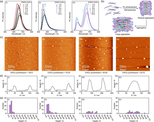
(a) PL spectra of (i) NGR, (ii) NGB, and (ii) NGRB in the mixed solvents of chloroform and cyclohexane. (b) Schematic representation of the self-assembly of NGRB causing PL enhancement. (c) AFM (mica, 2×2 μm2, tapping mode) images of NGRB prepared from (i) chloroform, (ii) chloroform : cyclohexane=7 : 3, (iii) chloroform : cyclohexane=5 : 5, and (iv) chloroform : cyclohexane=3 : 7. The samples were prepared by sonication of the solution of NGRB for 1 h, standing the solutions for 1 h at room temperature, spin coating onto mica substrates, and drying under reduced pressure for 1 day. [NGRB]=1.0×10⁻³ mg mL−1. (d) Height profiles of the cross sections of the blue lines in (i), (ii), (iii), and (iv). (e) Height distribution of the self-assembled NGRB on the AFM images of (i)–(iv).
To confirm the structures of the aggregates, atomic force microscopy (AFM) images of NGRB prepared from four distinct solvents were recorded (Figure 3c). A sample prepared from a chloroform solution of NGRB ([NGRB]=1.0×10⁻³ mg mL−1) provided an AFM image showing a single-layer NGRB scattered on a mica substrate with an average lateral size of 27±7 nm (Figure 3c-(i)). Both single-layer NGRB and multilayer NGRB were observed (Figure 3d-(i) and 3e-(i)). With increasing volume of cyclohexane relative to chloroform, the single-layer NGRB gradually decreased (Figure 3c-(ii) and -(iii), 3d-(ii) and -(iii) and 3e-(ii) and -(iii)), and large aggregates were observed on the mica substrate (Figure 3c-(iv), 3d-(iv), and 3e-(iv)). When the thickness of the single-layer NGRB was approximately 5 Å, the aggregate shown in Figure 3d-(iv) was composed of 18 layers of NGRB. The width of the aggregate was larger than that of a single layer (Figure 3d-(iv) vs. 3d-(i)), suggesting that NGRB organized stacked aggregates, and the aggregation of the stacked aggregates produced large aggregates. The PL spectra of NGRB (Figure 3a-(iii)) suggested that the stacked aggregates contribute to the PL enhancement (Figure 3b). Similar trends were observed in the AFM images of NGR and NGB (Figures S45 and S46 in the Supporting Information). With increasing volume of cyclohexane relative to chloroform, the height distributions of NGR and NGB gradually changed. Based on the histograms of the three NGs, NGRB and NGB tended to be organized as highly stacked structures compared to NGR.
With the lipophilic and PL enhancement properties of NGR, NGB, and NGRB in hand, we fabricated polymer films containing these NGs. PVDF was selected for its stability, flexibility, and colorlessness.48 Figure 4a shows a scheme of the fabrication of the PVDF films. PVDF (0.34 mg) was dissolved in DMF (2 mL), followed by the addition of a THF solution (0.5 mL) of NGR, NGB, or NGRB (0.1 mg mL−1) to obtain a homogeneous solution.49 The mixture was drop-cast onto a glass plate and dried for 2 min at 50 °C to obtain colorless PVDF films containing the NGs. The flexible nature of the films enabled the films to be peeled from the glass plate with a pincer (a digital image in Figure 4a).

(a) Fabrication of the PVDF films of NGR, NGB, and NGRB and a digital image of the PVDF film of NGRB. (b) Digital images of the PVDF films of NGR (left), NGB (center), and NGRB (right) (λex=365 nm) prepared from THF solutions of the NGs (0.1 mg mL−1). (c) PVDF film of NGRB prepared from a THF solution of NGRB (0.5 mg mL−1). (d) Characters “HU” (=Hiroshima University) crafted by cutting the PVDF film of NGB. (e) Figure of a crane (Tsuru in Japanese) obtained by folding a piece of a square PVDF film of NGRB.
Figure 4b shows digital images of NGR, NGB, and NGRB-dispersed PVDF films irradiated with 365 nm light. The films of NGR and NGB emitted red and blue color, respectively, and that of NGRB reproduced purple color. These results showed the emission of these NGs in the PVDF films. Similar to NGRB in the solutions, the relative PL intensities of NGRB in the PVDF film can be regulated by the excitation wavelength (Figure S50 in the Supporting Information). The color coordinates demonstrate that the PVDF film can reproduce various PL colors. Further, NGRB can well reproduce the PL color of the mixture of NGR and NGB (Figure S54 in the Supporting Information). This again demonstrates that the color can be tuned on a single substrate.
We also checked the photodegradability and thermal stability of the PVDF films. When the PVDF films were kept irradiation at 360 nm at room temperature, the PL intensity of the fluorophores was decreased likely due to the decompositions of the fluorophores (Figure S51 in the Supporting Information). Ph-TPA of NGB was decreased more rapidly than BTD-TPA of NGR. Interestingly, the PL intensity of Ph-TPA of NGRB was decreased more slowly than that of NGB.50 The PVDF films were confirmed to be thermally stable below 50 °C (Figure S52 in the Supporting Information).
More concentrated NGRB in PVDF films were fabricated by similar procedures to increase its density in the PVDF films. A five times more concentrated sample (0.5 mg mL−1 in a THF solution) emitted purple color (Figure 4c); however, in the case of ten times more concentrated sample, the PVDF film appeared brown due to presence of a dark brown solid of NGRB, and purple color was not observed (Figure S47 in the Supporting Information). Hence, the concentration could be increased up to 0.5 mg mL−1 to fabricate photoemitting PVDF films. A transmission electron microscope image of the PVDF film of NGRB showed many shadowed areas around 100 nm likely due to the aggregation of NGRB in the PVDF film (Figure S48 in the Supporting Information).
The flexible nature of the PVDF films allowed the characters to be cut from the films. Figure 4d shows blue light emitting characters of “H” and “U” obtained from the PVDF film of NGB (Figure 4d). Furthermore, a piece of a square PVDF film of NGRB could be shaped into a figure of a crane (Figure 4e).
Conclusion
In conclusion, we developed NGs carrying distinct kinds of fluorophores. The addition of the blue- and red-light-emitting fluorophores into the edges achieved dual emission, and purple color, an intermediate color of the blue and red light, was reproduced. Although the optical properties of the NGs are complex and the effect of the electron transfer should be considered in fine-tuning the PL color, the present protocol could be utilized for the reproduction of other intermediate colors. Furthermore, the aggregation of the NGs, which is inevitable for graphitic materials, could be exploited for AIEE-like PL enhancements. The lipophilicity, PL properties, and PL enhancement enable the attainment of the PVDF films emitting red, blue, and purple light. Our results demonstrated that NGs can display various functions at the same time, such as lipophilicity, dual emission, and PL enhancement, by edge functionalization. This feature is an advantage of NG-organic hybrid materials.
Acknowledgments
The authors are grateful to Dr. Maeda and Ms. Tomoko Amimoto of the Natural Science Center for Basic Research Development (N-BARD), Hiroshima University for facilitating the TEM and HRMS measurements. This work was supported by the Nippon Sheet Glass Foundation, Iketani Science and Technology Foundation, The Urakami Scholarship Foundation, ENEOS Tonen General Research/Development Encouragement & Scholarship Foundation, JSPS KAKENHI, Grants-in-Aid for Transformative Research Areas, “Condensed Conjugation” Grant Number JP21H05491 and “Materials Science of Meso-Hierarchy” Grant Number JP23H04873, and Grant-in-Aid for Scientific Research (A) Grant Number JP21H04685. We also acknowledge support from the KEIRIN JKA, Grant Number 2023M-419.
Conflict of interests
The authors declare no conflict of interest.
Open Research
Data Availability Statement
The data that support the findings of this study are available in the supplementary material of this article.


