Universal Sub-Nanoreactor Strategy for Synthesis of Yolk-Shell MoS2 Supported Single Atom Electrocatalysts toward Robust Hydrogen Evolution Reaction
Abstract
The coordination structure determines the electrocatalytic performances of single atom catalysts (SACs), while it remains a challenge to precisely regulate their spatial location and coordination environment. Herein, we report a universal sub-nanoreactor strategy for synthesis of yolk-shell MoS2 supported single atom electrocatalysts with dual-anchored microenvironment of vacancy-enriched MoS2 and intercalation carbon toward robust hydrogen-evolution reaction. Theoretical calculations reveal that the “E-Lock” and “E-Channel” are conducive to stabilize and activate metal single atoms. A group of SACs is subsequently produced with the assistance of sulfur vacancy and intercalation carbon in the yolk-shell sub-nanoreactor. The optimized C−Co−MoS2 yields the lowest overpotential (η10=17 mV) compared with previously reported MoS2-based electrocatalysts to date, and also affords a 5–9 fold improvement in activity even comparing with those as-prepared single-anchored analogues. Theoretical results and in situ characterizations unveil its active center and durability. This work provides a universal pathway to design efficient catalysts for electro-refinery.
Introduction
Hydrogen energy is vital to deal with energy demand and carbon neutrality, and the electrochemical water splitting is a feasible technology to produce green hydrogen.1 Acidic hydrogen-evolution electrocatalysis which owns high efficiency and pure production gains wide popularity. In the past decades, numerous efforts are devoted to ameliorate the electrocatalysts for reducing cost and retrenching energy consumption.2 Up to now, Pt/C is still the ideal catalyst, while the high-cost and low-reserve of Pt drive people to explore other economical and efficient electrocatalysts.3 Single atom catalysts (SACs) which possesses the maximization atomic efficiency have aroused widespread attention since Zhang et. al first proposed the conception.4 Nevertheless, high surface energy makes the single atoms prefer to agglomerate in the electrocatalysis. Benefitting from the strong metal-support interactions, the substrate can stabilize the single atoms and tune electronic structures of the SACs.5 Therefore, it is particularly desirable to exploit ideal support for the controllable synthesis of SACs hereby simultaneously resolving the issues of activity and durability.6
Among the reported substrates, carbon-based materials could provide rich sites for metal single atoms loading due to their large specific surface area, abundant defects as well as the heteroatoms doping.7 The metal-nitrogen-carbon (M−Nx−C) SACs those metal single atoms anchored on N-doped carbon support are the typical representatives.8 Specially, the intrinsic activity and site density of the M−Nx−C SACs can be adjusted by tailoring the coordination structures in terms of saturation, unsaturation, and oversaturation, resulting in customized catalytic performances.9 Furthermore, theory and experiment confirm that the stability and selectivity of metal single atoms could be tailored via optimizing the local microenvironment in the heteroatom-doped carbon support.10 By far, universal strategies such as ligand mediated method,11 cascade anchoring strategy,12 capture-bonding super assembly strategy,13 graphene quantum dots assist14 are proposed for the synthesis of carbon-based SACs, and the electrocatalysis have achieved comparable activity than Pt/C to some extent. As another class of SACs, non-carbon-based support such as metal oxides, metal sulfides, carbides, nitrides, phosphides, organic frameworks etc. materials have also attract significant attention owning to their particular merits in stabilizing/dispersing single atoms such as adjustable configurations, compositions, and facets.15 The corresponding anchoring mechanisms in the support are as follows: (i) cation vacancy: cation vacancies in the support can afford large space for the atom adsorption, modulate the electron density at the interface, and activate the local metal-atoms for boosted reaction kinetics;16 (ii) anion vacancy: with the assistance of space confine or charge attract, the anion vacancies including O, S, Se, and P are acted as the sites for metal atoms anchoring to achieve SACs with enhanced metal-metal and metal-support interactions, thereby developing high-active electrocatalysts;5a, 15b, 17 (iii) defined strategy: the crystal-facet-dependent and strain are also effective approach to create the strong interactions for achieving a synergistically enhanced catalytic behavior.18 Overall, the activity, selectivity, and durability of the metal single atoms have also been simultaneously enhanced via introducing the single-support.
Recently, the carbon-based SACs which were co-anchored by heteroatoms in the form of horizontal,19 axial,20 and asymmetry21 coordination structures are demonstrated more advantages than the single-anchored catalysts. Because of the discrepant electronegativity, the single atom Ru could be anchored by Ni atom forming the MoS2-based SACs.22 Based on the above findings, most reports focus on the regulation of coordination structures of SACs over carbon- or non-carbon-based support for achieving promoted electrocatalysis, while it remains a challenge for the precise development of SACs with spatial location and dual-anchored local microenvironment in the MoS2 and carbon so far.
Herein, we prepared dual-anchored C−M−MoS2 SACs (M=Co, Ni, Fe, Zn, W, Cu, Mn, and Cd) by using a universal sub-nanoreactor strategy for boosted hydrogen-evolution electrocatalysis. Theoretically, density functional theory (DFT) calculations predicted that the feasibility of single atoms in terms of activity and stability in the vacancy-enriched MoS2 and intercalation carbon. Experimentally, the sub-nanoreactor strategy was universal to produce a group of MoS2 supported single atom electrocatalysts with dual-anchored local microenvironment over yolk-shell C−MoS2 host. The resultant C−Co−MoS2 presented more excellent hydrogen-evolution performance than the MoS2-based SACs reported by far. The finite element analysis (FEA) results showed that the intensity and distribution of the current density was much better on the dual-anchored electrode than those on the single-anchored electrodes. The actual active site and the durability of the C−Co−MoS2 were revealed by the DFT results and in situ XRD and Raman characterization.
Results and Discussion
DFT calculations were first utilized to conceptually guide the rational design of the SACs. The model that consisted of sulfur vacancy and intercalation carbon in the MoS2 was built (Figure S1). According to the electron density differences (EDDs) and corresponding Bader charge analysis (Figure 1a), the electron deficiency of 0.2|e| generated at the sulfur vacancy forming the “E-Lock”, which could capture the negative metal ion groups and in situ anchor the metal atoms. The metal atoms occupied the sulfur vacancies to coordinate with Mo and intercalation carbon forming the dual-coordinated C−M−Mo model, and the single-anchored M−MoS2 and C−M models were also constructed for comparison (Figure S2–4). The atoms numbers in the dual-support were indexed and shown in Figure S1. The top view slices of the EDDs that crossed C14, M, and Mo5 (red dotted box in Figure 1a) and Bader charge analysis (Table S1, 2) were emerged to gain more insights into the electron transfer. The charges were redistributed and a directed electron transfer channel (“E-Channel”) of “Mo5→M→C14′′ generated in the C−Fe−Mo, C−Co−Mo, C−Cu−Mo, and C−Ni−Mo. In contrast, the electron transfer outflowed with a radiated route of “Mo5←M→C14′′ in C−W−Mo, C−Mn−Mo, C−Cd−Mo, and C−Zn−Mo.
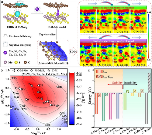
Theoretical calculations of the activity and stability. (a) The EDDs in the C−MoS2, the structure models of C−M−Mo, the top view slice and the corresponding EDDs in the C−M−Mo. (b) The 3D volcano plot with ΔGH(1), ΔGH(2), and log (i0) for the C−M−Mo, M−MoS2, and C−M. (c) The stability calculations of metal atoms in the C−M−Mo. The red and blue color in b represents high activity and low activity, respectively.
For the SACs,23 the intermediates those adsorbing one H atom (MH) and two H atoms (HMH) should be considered in the HER process. As shown in Table S3 and Figure S5, the calculated H−H distances were between 0.77 and 0.85 Å implying that the dihydrogen complexes (HMH) could generate in the C−M−Mo. Therefore, the log (i0) determined by two kinds of Gibbs free energy (ΔGH(1) and ΔGH(2)) could be a descriptor to evaluate the HER activity (Table S4). According to the 3D volcano plot (Figure 1b), the dual-anchored C−M−Mo which occupied the central position possessed much better theoretical activity than the single-anchored M−MoS2 and C−M. The enhanced activity could be attributed to the built directed “E-Channel” and radiated electron transfer route in the dual-anchored models. The activity order in the C−M−Mo is W>Co>Zn>Fe>Cd>Cu>Ni>Mn.
Besides the activity, we further took in account the stability of the metal atoms in the single- and dual-anchored models as another descriptor. Single atom can be stabilized in the support when both the adsorption energy (Eads) and difference-value (Eads–Ecoh) are negative values.24 As shown in Figure 1c, all the calculated Eads values were negative in the C−M−Mo models, signifying that the adsorption of metal atoms occurred spontaneously in the dual-support. The Eads–Ecoh values of C−Mn−Mo, C−Ni−Mo, C−Co−Mo, and C−Fe−Mo were calculated to be −0.75, −0.49, −0.24, and −0.19 eV, implying that the Mn, Ni, Co, and Fe atoms can be steadily settled in the dual-support to against either the metals atoms being leached or aggregation. In contrast, the other four models (Cu, Cd, Zn, and W) with positive difference-value could not stably exist in the dual-support. For the single-anchored SACs, only Co and Ni atoms can be stabilized in the MoS2 support, and all the selected metal atoms can't exist in the carbon support (Figure S6). Based on the calculations, Mn, Ni, Co, and Fe atoms could be confined by the intercalation carbon and sulfur vacancy generating stable dual-anchored SACs.
Seen from the summary of stability and activity for different metal single atoms in the single- and dual-anchored models shown in Figure S7, the hydrogen-evolution performances could be efficiently tailored via the modulation of local microenvironment at the interface. Combining the above two descriptors, the C−Ni−Mo, C−Co−Mo, and C−Fe−Mo which owned the directed “E-Channel” presented much better activity than C−Mn−Mo with radiated electron transfer route. Seen from the volcano curve of charge transfer vs. log (i0) shown in Figure S8 (Table S1, 4), the C−Co−Mo with a suitable amount of charge transfer which could provide eclectic microenvironment for hydrogen adsorption-desorption exhibited the highest activity. The Bader charge analysis of the first and second shell coordination at Co atom revealed a charge transfer channel of “S9→Mo5→Co→C14′′ in the C−Co−Mo model (Table S5, Figure S9), which could be beneficial to modulate the electron density of Co atom. Therefore, the C−Co−Mo SAC with the directed “E-Channel” and effective “E-lock” which combined the activity and stability could deliver a balanced hydrogen-evolution performance theoretically.
To verify above hypothesis, we prepared a group of dual-anchored C−M−MoS2 SACs via the sub-nanoreactor engineering experimentally (Figure 2a). Specifically, the monodispersed and uniform yolk-shell C−MoS2 sub-nanoreactor which owned the local microenvironment of sulfur vacancy and intercalation carbon was first developed and utilized as the dual-support based on our previous researches.6a, 17a According to the theoretical prediction, the MXn− with negative charge could be captured by the “E-Lock” at the sulfur vacancy sites at room temperature. The metal M atoms were subsequently in situ loaded by coordinating with Mo and intercalation carbon at 750 °C, generating the “E-Channel” at the co-anchored C−M−Mo local interface. Different transition metal atoms including Zn, Cu, Ni, Fe, Co, Mn, W, and Cd have been attempted for spatially locating metal single atoms into the C−MoS2 support by a universal sub-nanoreactor strategy. The X-ray diffraction (XRD) patterns showed broad peaks of carbon and typical peaks of 2H−MoS2 (Figure S10). Interestingly, the expanded layer at 9.3° that was co-contributed by intercalation carbon and (002) facet of MoS2 always existed before and after metal atoms incorporation. The oriented-nanosheets onto the surfaces and the particle size of the monodispersed C−Co−MoS2 SAC kept almost unchanged after the single atom incorporation (Figure S11, 12).
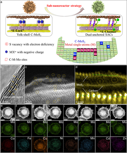
Universal synthesis and morphological characterizations of the C−M−MoS2 SACs. (a) Schematic illustration for the universal sub-nanoreactor synthesis strategy[A1] , (b) HRTEM image of the C−Co−MoS2. (c–d) AC-TEM images in the expanded layer of C−Co−MoS2, (e–l) HAADF and the corresponding EDS mapping images of the metal elements in the C−M−MoS2. The scale bars in e–l are 200 nm. The red and blue boxes of periodic table in (a) are the elements of the support and metal single atoms, respectively.
Transmission electron microscopy (TEM) and high-resolution TEM (HRTEM) images verified that the configuration of C−Co−MoS2 SAC remained the yolk-shell structure (Figure S21a, b). The interlayer distance was expanded to 0.96 nm from 0.62 nm because of the carbon intercalation in the (002) facet of MoS2 (Figure 2b). Obvious lattice fringes corresponding to the (100) plane of MoS2 and abundant vacancies could be identified in Figure S21c. According to the high angle annular dark field (HAADF) image by the spherical aberration corrected transmission electron microscopy (AC-TEM), the high bright marked by yellow dotted cycles can be easily found in the expanded layer and the surface (Figure 2c), demonstrating the most Co atoms could be embedded in the expanded layer of C−MoS2 support. Furthermore, the vertical carbon monolayer with low brightness can be found between the highly bright MoS2 monolayers based on the higher magnification AC-TEM image (Figure 2d). Atomic dots (yellow dotted cycles) which neither lied on the carbon monolayer nor on the MoS2 monolayer could be identified in the expanded layer, signifying the existence of MoS2 and carbon around Co atoms in the C−Co−MoS2 SAC. The HAADF and energy-dispersive X-ray spectroscopy (EDS) mapping images confirmed a uniform distribution of different Mo, S, C, and Co elements in the C−Co−MoS2 (Figure 2e and Figure S30a). The weight percentage of Co element is determined to be 1.54 % in the C−Co−MoS2 by inductively coupled plasma mass spectrometry (ICP-MS) (Table S6). The N2 physisorption isotherms and the corresponding pore size distribution verified the mesoporous and macroporous structure in the C−Co−MoS2 (Figure S31). The porous yolk-shell configuration could contribute to the mesoscale mass diffusion in the HER process (Figure S32, PPT-FEA). According to the FESEM, TEM, HAADF, and the corresponding EDS mapping images, the MoS2-based catalysts with various metal elements such as Fe, Cu, Ni, W, Mn, Cd, and Zn can also be prepared successfully (Figure S13–30 and Figure 2f–l).
Electron paramagnetic resonance (EPR) was conducted to investigate the evolution of sulfur vacancies with the single atoms anchoring and intercalation carbon. As shown in Figure 3a, the sulfur vacancy signal at g-factor of 2.003 increased when introducing intercalation carbon in the MoS2. It could be attributed to that the carbon in situ generated in the expanded layer of MoS2 leading to the crystal distortion, thereby enhancing the sulfur vacancy and “E-Lock” in the sub-nanoreactor. In addition, the signal was slightly reduced after Co addition, which could be as a result of the incorporation of single atom Co into the vacancy position. According to the comparison of Raman spectra, the peaks at 380 and 403.1 cm−1 were assigned as the vibration configurations of E12g and A1g of 2H−MoS2 in the C−Co−MoS2 SAC. The separation (Δ) decreased from 23.1 cm−1 of C−MoS2 to 21.2 cm−1 of C−Co−MoS2, signifying that single atom Co could interact with Mo and affect the vibration of the Mo−S on this account (Figure 3b). The peaks at 1356 and 1577 cm−1 belonging to the graphitic and disordered carbon can be found in the C−MoS2 and C−Co−MoS2 SAC. As expected, the other SACs presented a similar shift of such vibrations according to the comparison of the Raman peaks (Figure S33).
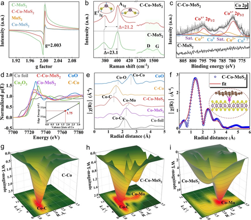
Structure information of the as-prepared MoS2-based materials. (a) The comparison of EPR data for the MoS2, C−MoS2, Co−MoS2, and C−Co−MoS2, (b) Raman profiles and (c) high-resolution XPS spectra of Co 2p in the C−MoS2 and C−Co−MoS2, (d) Normalized K-edge XANES of Co. (e) EXAFS spectra of Co K-edge, (f) Fitting curve of EXAFS spectra for Co at R space, (g–i) WT of Co K-edge. Inset in (b) is Raman vibration models of E12g and A1g in the MoS2. Inset in (d) is Co valence state obtained from Co K-edge XANES. Inset in (f) is the corresponding atomic structure model of C−Co−MoS2.
X-ray photoelectron spectroscopy (XPS) was further conducted to check the chemical states onto the surface of the SACs. Peaks belonging to the Mo, Co, S, and C were identified by the survey spectrum of C−Co−MoS2 SAC (Figure S34a). The Co 2p orbit of C−Co−MoS2 SAC was fitted by four couple peaks including the Co0, Cox+, Co2+, and satellite peaks. Two peaks at 779.5 and 794.5 eV which were between the Co0 and Co2+ were dominant, indicating that the chemical state of Co was mainly between 0 and 2 (Figure 3c). Compared with the C−MoS2, both the peaks of Mo4+ and S2− were positively shifted in the C−Co−MoS2 (Figure S34b, c). The deviation could be due to the electron transfer from Mo to Co. Besides, a peak at 284.0 eV assigned to the C−Co species was verified in the C 1s XPS spectrum (Figure S34d). The Co 2p orbits of Co−MoS2 and C−Co were collected to distinguish the chemical bonds around Co atom in the different support. As shown in Figure S35a, the binding energy of Cox+ in the C−Co−MoS2 showed positive shift of 0.30 eV than that in the Co−MoS2, while it reduced by 0.42 eV compared with the binding energy in the C−Co, respectively. The electron density differences and corresponding Bader charge analysis of Co in different support were studied to clarify this change. As shown in Figure S35b, the charge of 0.104|e| transferred from MoS2 to Co atom in the Co−MoS2 support, while it became the outflow of Co atom in the C−Co−MoS2 and C−Co support. The amounts of charge transfer were calculated to be −0.160|e| and −0.552|e| for the C−Co−MoS2 and C−Co, respectively. The degree and direction of electron transfer matched with the shift of binding energy in the high-resolution XPS spectra of Co 2p. The experimental XPS shift and theoretical charge transfer together verified that the bonding environment of Co element in the C−Co−MoS2 could be different from those in the Co−MoS2 and C−Co.
To further clarify the chemical valence and local structure, X- ray absorption fine structure (XAFS) of Co K-edge in the C−Co−MoS2, Co−MoS2, and C−Co were collected. By contrast, the position of the absorption edge in the X-ray absorption near-edge structure (XANES) of C−Co−MoS2 was different from those of Co−MoS2 and C−Co, and the positions in the as-prepared materials were between those in the Co foil and CoO references (Figure 3d). According to the curve of linear relation obtained using area integration method, the accurate state of Co was +1.75 in the C−Co−MoS2. Fourier-transformation extended X-ray absorption fine structure (FT-EXAFS) results revealed that the main peak was belonging to Co−C at 1.39 Å in the C−Co−MoS2, which is different from Co−O peak in the CoO and Co−C peak in the C−Co. No Co−Co peak was detected indicating that Co element mainly existed in the single atom form (Figure 3e). In addition, the peak at 2.43 Å could be described as the formation of Co−Mo coordination in the C−Co−MoS2, which showed red shift compared to that of Co−MoS2. The XANES and EXAFS results verified that the Co atoms could steer different local microenvironment in the single- and dual-anchored materials. The related fitting in K space and R space were plotted to ensure the chemical configurations (Figure S36 and Figure 3f), and the detailed setting parameters were shown in Supporting Information Table S7. According to the fitting results, Co atom could coordinate with 3 C atoms and 0.5 Mo atom. Thus, the atomic structure could be C3−Co−Mo0.5, and the corresponding coordination model was given in inset of Figure 3f. Furthermore, the wavelet transforms (WT) presented the structure information of Co−C and Co−Mo bonds in the C−Co−MoS2, respectively (Figure 3h), which was distinctly different compared with those in the C−Co, Co−MoS2 (Figure 3g, i), Co foil and CoO references (Figure S37a, b). Combining the AC-TEM images, XPS spectra, and XAFS analysis, Co single atom bonded with carbon and Mo forming the dual-anchored C−Co−Mo coordination microenvironment in the C−Co−MoS2.
Pristine MoS2 and single-anchored Co−MoS2 and C−Co catalysts were also synthesized for the comparison with the as-prepared C−MoS2 sub-nanoreactor and dual-anchored MoS2-based electrocatalysts. The structural and composite characterizations including XRD patterns, TEM images, EDS data, and Raman spectra were shown in Figure S38–42. We first conducted the HER performances of single- and dual-anchored electrocatalysts using a three-electrode system in acid. According to the polarization curves (Figure 4a and Figure S43a) and Tafel slopes (Figure S43b), the corresponding summary of overpotentials and Tafel slopes were listed in Figure 4b. By contrast, the C−Co−MoS2 electrode exhibited an overpotential of 17 mV at 10 mA cm−2, which was much better compared with the other dual-anchored MoS2 electrocatalysts. Furthermore, the activity of C−Co−MoS2 represented an improvement of 5-fold and 9-fold versus those of single-anchored Co−MoS2 and C−Co, respectively. The ultra-low Tafel slope indicated the C−Co−MoS2 catalyst proceeds via a combined Volmer–Heyrovsky mechanism for hydrogen-evolution electrocatalysis. Noticeably, the C−Co−MoS2 exhibited more excellent activity than commercial Pt/C. Seen from the TEM images after the LSV measurement (Figure S44), nanoparticles were found in the C−M−MoS2 (M=Cu, Cd, Zn, W), verifying that these four metal atoms could be instable in the dual-support. After eliminating the above four SACs, the C−Co−MoS2 with directed “E-Channel” and suitable charge transfer at the interface presented much better HER activity than the other C−M−MoS2 (M=Mn, Ni, and Fe). The experimental results were consistent with the calculated descriptors (Figure 1b, c). To better understand the coordination environment of Co on the activity, the catalyst that Co replaced the Mo atom forming the Co doped C−MoxCo1-xS2 material was also produced for comparison. Obviously, the C−Co−MoS2 SAC with dual-anchored local environment showed a much lower overpotential of 17 mV and a Tafel slope of 32 mV dec−1 (Figure S45). Figure 4c showed the comparison of overpotentials MoS2-based electrocatalysts applied for acidic HER, and the dual-anchored C−Co−MoS2 catalyst demonstrated much higher activity than the non-precious metals and precious metals SACs reported to date (Table S8).
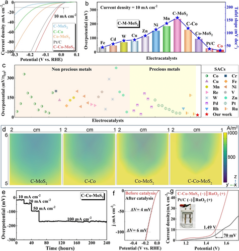
Electrochemical measurements and FEA results of the as-prepared SACs in acid. (a) Polarization curves of the C−MoS2, single-, and dual-anchored electrodes, (b) The summary of overpotentials and Tafel slopes, (c) The comparison of the overpotentials for C−Co−MoS2 and MoS2-based SACs in the literature, (d) FEA simulations of the C−MoS2, single-, and dual-anchored electrodes, (e) Continuously electrocatalytic test of the C−Co−MoS2, (f) The polarization curves of the C−Co−MoS2 before and after catalysis, (g) The comparison of the polarization curves in the overall water splitting. Inset of g is the photograph of the overall water splitting device. Inset in (g) is digital photograph of two-electrode hydrolysis system.
According to the test conditions, the COMSOL Multiphysics solver was employed to simulate the current density on the electrodes in the built three-electrode system (Figure S46). The Butler–Volmer equation  was used to describe the relation between charge transfer and overpotential, and the corresponding FEA results were displayed in Figure 4d. Obviously, the intensity and distribution of the current density was much better on the dual-anchored C−Co−MoS2 electrode than those on the Co−MoS2, C−Co, and C−MoS2 electrodes, signifying that the C−Co−MoS2 catalyst could supply higher water splitting efficiency. The superior activity could be attributed to the formation of “E-Channel” and the low energy barrier at the C−Co−Mo interface, which accelerated the electron transfer and promoted the hydrogen adsorption-desorption, respectively.
The Electrochemical Impedance Spectroscopy (EIS) measurements of single- and dual-anchored SACs were used to gain more insight into the electrode kinetics (Figure S43c and S47a). Obviously, the C−Co−MoS2 electrode exhibited the lowest transfer resistance, meaning the highly improved charge transfer kinetics from catalyst to electrode. Furthermore, all the electrocatalysts presented approximate rectangles at different scanning rate from 20–200 mV s−1 (Figure S48, 49). Accordingly, the C−Co−MoS2 delivered a Cdl value of 9.25 mF cm−2, which was 3 times higher than that of the C−MoS2, demonstrating that the electrocatalytic activity was greatly improved after Co single atom loading. Seen from the turnover frequency (TOF) curves (Figure S43d and 47b), the C−Co−MoS2 SAC showed more activity densities than other catalysts, and it delivered a TOF value of 0.046 s−1 at 100 mV, which shows ca. 3-folds, 10-folds, and 30-folds increase in TOF values than that for Co−MoS2, C−Co, and C−MoS2, respectively.
Continuously monitored measurement was performed at 10, 20, 50, and 100 mA cm−2 to study the durability of the C−Co−MoS2 electrocatalyst (Figure 4e). As a result, the overpotentials only showed slight recession after continuously working at both low and high current density for 240 h, confirming the excellent stability and flexibility. Seen from the comparison of the polarization curves before and after the electrocatalysis, the overpotentials at 50 and 100 mA cm−2 only increased by 4 and 6 mV further verifying the sustainable activity of C−Co−MoS2 SAC (Figure 4f). A two-electrode hydrolysis system was fabricated by the C−Co−MoS2 (−)‖RuO2 (+) electrodes to check the overall water splitting performance in acid media. Seen from the comparison of movies recorded onto the surfaces of the cathodes (Movie S1, S2), the gas bubbles generated and left more rapidly on the C−Co−MoS2 (−) electrode than those on the commercial Pt/C (−) electrode, indicating that the C−Co−MoS2 device could be more efficient. Specifically, the cell voltage was 1.49 V to achieve 10 mA cm−2 for the C−Co−MoS2 electrode, which is much lower than 1.56 V of commercial precious metal electrode (Figure 4g). Additionally, the C−Co−MoS2 electrode demonstrated much higher activity in the overall water splitting compared with the hybrid electrocatalysts reported in the literature (Figure S50a and Table S9). The C−Co−MoS2 showed the overpotential increase of 6 and 10 mV at 50 and 10 mA cm−2 after electrocatalysis for 200 times, respectively, confirming the durability of the C−Co−MoS2 catalyst in the acidic overall water splitting (Figure S50b).
DFT calculations were further performed to identify the actual catalytic center in the C−Co−MoS2. As shown in Figure 5a, four possible positions were designed for the hydrogen adsorption including S site, C site, Co site, and Mo site. As a result, the ΔGH(1) and ΔGH(2) were calculated to be 0.19 and −0.12 eV at Co site which were both lower than those at the other sites. The highest log (i0) value indicated that the thermodynamics process for hydrogen adsorption-desorption was more toilless at Co site, and the real catalytic center could be the Co site. The electron change between Co and H was subsequently investigated in the C−Co−Mo model (Table S10, Figure 5b). After the first H atom adsorption, the electron density around Co atom increased, which was conductive to adsorb the second H atom. Then the electron density of Co decreased when adsorbing the second H atom, which could be attributed to the electron transfer from Co to H in the cathodic reaction (Figure S51). The in situ characterizations were performed to monitoring the evolution of structural information in the C−Co−MoS2. Sharp peaks of the ITO glass to the (Figure S52) and wide peak from 23 to 48° which were belonging electrolyte could be seen in the in situ XRD patterns, respectively. When applied the voltage from 0.14 to 0.54 V, no obvious change could be found in the expanded layer, intercalation carbon, and MoS2 confirming the durability of the as-prepared C−Co−MoS2 SAC (Figure 5c).
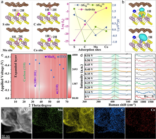
Identification of the catalytic center, in situ characterizations, and durability of the C−Co−MoS2 SAC. (a) The models of different sites for hydrogen adsorption and the resultant ΔGH(1), ΔGH(2), and log (i0), (b) The EDDs of hydrogen adsorbed C−Co−Mo model, (c) In situ XRD patterns, (d) In situ Raman spectra, (e) High magnification HAADF at the edge and EDS mapping images. The iso-surface level in b is set to 0.001 e/Bohr3 when adsorb one H atom, set to 0.02 e/Bohr3 when adsorb two H atoms, and the blue and yellow represent the electron depletion and accumulation areas, respectively. The right part in (d) is the in situ Raman results at high wavenumber range.
Seen from the in situ Raman spectra shown in Figure 5d, the E12g and A1g vibrations of 2H−MoS2 always existed with the increase of applying voltage. No distinct difference was observed because of the wide and weak feature of the E12g vibration, while the position of the A1g vibration changed with the raise of the setting voltage. Specifically, a shoulder peak at 404.5 cm−1 appeared around the primary peak (403 cm−1) when applying voltage of 0.25 V, and it gradually raised and converted to the strongest peak at 0.5 V. Based on the EDDs of hydrogen adsorbed at Co site (Figure 5b), the positive Raman shift of A1g vibration in the MoS2 could be attributed to the charge redistribution around Co, thereby affecting the local environment of Mo−S in the “E-Channel”, which further indicated that the Co site as the catalytic center could participate in the HER process.
The morphology (Figure S53a), the crystal (Figure S53b), and the expanded layer (Figure S53c) of the C−Co−MoS2 were studied to verify the unchanged microstructure. The overall microsphere, the amplified HAADF at the edge, and the EDS mapping images together verified that the Mo, S, C, and Co elements were uniformly distributed and no metal agglomeration happened after the electrocatalysis (Figure 5e and Figure S54). According to the ICP-MS result, the Co content in the C−Co−MoS2 almost maintained consistent before and after catalytic reaction for 240 h, which further revealed the robustness of the single atom Co in the dual-support (Table S6).
Conclusion
In summary, we have reported a universal sub-nanoreactor strategy to precisely regulate the spatial location and local microenvironment of metal single atoms over yolk-shell C−MoS2 dual-support for robust hydrogen-evolution catalysis in acidic condition. DFT calculations reveal that metal single atoms could not only stabilize in the dual-support with the assistance of the effective “E-Lock” at the sulfur vacancy site but also create a tunable electron transfer at the C−M−Mo interface. According to the stability and activity descriptors, the dual-anchored C−Co−Mo could possess superior hydrogen-evolution performance. Experimentally, the sulfur vacancy and intercalation carbon in the yolk-shell C−MoS2 sub-nanoreactor are utilized as the dual-support to afford for the formation of “E-Lock” and “E-Channel” so that they can capture negative metal groups and in situ anchor the metal atoms in the expanded layer. Interestingly, this sub-nanoreactor strategy is universal for the immobilization of single atoms to yield a group of dual-anchored C−M−MoS2 SACs. The resultant C−Co−MoS2 with the particular dual-anchored microenvironment of vacancy-enriched MoS2 and intercalation carbon exhibits much higher hydrogen-evolution activity than the MoS2-based SACs reported to date. Furthermore, the activity of C−Co−MoS2 represents a significant improvement compared with those of single-anchored Co−MoS2 and C−Co catalysts, respectively. FEA simulations reveal that the current density is much better on the C−Co−MoS2 electrode in terms of intensity and distribution compared with those on the single-anchored electrodes. DFT calculations and in situ characterizations together verify the actual catalytic center and durability of the electrocatalyst. This work involves the precise optimization of coordination structures of metal single atoms in the dual-support, and could shed a light on the preparation of advanced electrocatalysts via the microenvironment engineering of sub-nanoreactor.
Acknowledgments
The authors thank funds from National Natural Science Foundation of China (52002359 and 22279139) and Henan Provincial Science and Technology Research Project (No. 222102240020). We gratefully acknowledge National Supercomputing Center in Zhengzhou, P. R. China for providing the computational nodes, and thank the COMSOL Co., Ltd. in Shanghai, P. R. China for providing the license.
Conflict of interest
The authors declare no conflict of interest.
Open Research
Data Availability Statement
The data that support the findings of this study are available in the supplementary material of this article.


