Wide-Beam X-Ray Source Target Thermal Management Simulation Using Inner Jet Cooling
Abstract
A wide-beam area X-ray source has been proposed as a practical replacement for synchrotron sources in clinical DEI applications. Due to a wide X-ray illumination area, a decrease in X-ray flux is expected and thus high electron beam currents up to 3A are considered. To ensure the target performance without deterioration, melting, cracking, or even evaporation, an active cooling system is required for the target block in order to remove the heat and allow for sufficient scanning time. In this study, jet cooling of the target back is investigated for a prototype proof-of-principle target. The prototype target was simulated with the transient k-ɛ turbulence multiphysics model in ANSYS CFX. The simulations were conducted at a heat flux of 1.8 × 10⁷ W/m2, consistent with values anticipated for a full scale target. The simulation results show that the target temperature exceeds the copper melting point in 2 seconds at inlet velocities below 2 m/s. Also, critical heat flux calculations show that a 1.5 m/s inlet velocity at atmospheric pressure is a lower limit for prevention of target burnout using water as a coolant. Inlet velocities in excess of 2 m/s allows for steady-state operation while satisfying all thermal design constraints.
1. Introduction
In the proposed compact wide-beam X-ray source for diffraction enhanced imaging applications, highly collimated, high intensity photon flux is a major requirement [1–3]. Conventional X-ray tubes cannot meet these requirements due to their relatively low X-ray flux and the fan shape of the X-ray beam. To increase X-ray flux to compete with a synchrotron radiation beam, a high electron beam current (up to 3A) is proposed in conjunction with a large X-ray illumination area. Heat removal in a conventional X-ray source is not a critical issue because lower electron beam currents are used and a rotating target allows for spreading the heat flux over a larger area of the target. Conventional X-ray tubes which use stationary targets are passively cooled with air or oil [4]. The wide-beam X-ray source in this study has a stationary target (anode) and hence heat removal at high beam currents is essential. For a device expected to operate at the commercial level, a 3A beam current would be required in order to generate the necessary high X-ray flux. At 60 kV acceleration potential with 3A beam current, the total power on the target is 180 kW that requires special thermal management for target heat removal. The estimated scanning time of a DEI-based wide-beam X-ray system is ~20 seconds during which time the beam energy will be converted to heat energy on the target [5]. The cooling demands of such a target exceed the heat removal capacity of a passive cooling system and necessitate an active cooling system.
Early research work on the wide-beam X-ray system considered cryogenic cooling using liquid nitrogen through a contact or invaded cold finger [1]. This study revealed that heat removal via conduction utilizing liquid nitrogen could not obtain the required operating time before the target reached its melting temperature. In addition, the large thermal gradients and induced stresses in such a system would render it infeasible.
In this study, an inner impinging jet cooling method was employed for active cooling with water at atmospheric pressure and room temperature. The prototype proof-of-principle design was simulated using the ANSYS CFX finite element code [6].
2. General Considerations
Due to the high heat loads, target thermal management is an important issue for the proposed wide-beam X-ray system. Impinging jet cooling has been shown as an effective way to remove heat from the heated surface in various devices, and is considered in this study for target cooling [7]. Design of a jet cooling system requires maximizing the convective heat transfer from the target back while satisfying thermal limits associated with maximum target temperatures and critical heat flux. Convective heat transfer can be maximized by optimizing the geometry of the jet nozzle. To maintain target integrity, maximum target temperatures must remain well below the melt temperature. This is dictated by the target materials, geometry, and the efficiency of the target cooling system. If the heat flux at the coolant/target interface exceeds the critical point, transition to film boiling can occur, which degrades heat transfer and potentially leading to target failure [8].
2.1. Convective Heat Transfer Coefficient
2.2. Critical Heat Flux
3. Nozzle Design in the X-Ray Target
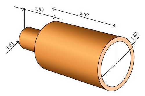
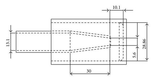
The wide-beam X-ray target is a cylindrical stationary target made of oxygen-free copper with a thin layer of molybdenum which acts as the X-ray-generating material [1]. Figure 1 illustrates the target design and its dimensions for a prototype proof-of-principle system fabricated by Brand X-Ray, LLC, Wood Dale, Ill, USA. Figure 2 shows the initial configuration of the jet nozzle.

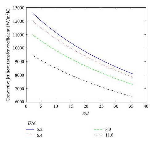
The convective heat transfer coefficient can be found from the Martin correlation (1). Based on the Reynolds number range for the correlation, the fluid velocity is between 0.2 m/sec and 33 m/sec, which is adequate for the proposed application. For a 1 m/sec inlet velocity, the Reynolds number varies from about 2 300 to 5 300 for values of d between 2.4 mm and 5.6 mm. The convective heat transfer coefficient as a function of S/d and D/d is shown in Figure 3. The convective heat transfer coefficient increases with the decrease in the S/d ratio. At any given S/d, the heat transfer coefficient also increases with the decrease in the D/d ratio. The diameter of the impingement surface D is fixed as the target diameter. As the Martin correlation has a lower limit on the D/d ratio of 5, this sets the optimum nozzle diameter, which in turn sets the optimum nozzle to target spacing. The optimized design is shown in Figure 4 with dimensions that correspond to an S/d ratio of 1.8 and D/d ratio of 5.15.
3.1. Equivalent Beam Current
The proof of principle target is designed to operate at the same heat flux as the industrial scale target. To provide the necessary photon flux for practical clinical or industrial screening applications, it has been shown to require power levels of 180 kW on the target for beam currents at 3A and an accelerating potential of −60 kVp [15]. For an industrial scale target area of 100 cm2, this implies an inward heat flux on the target of 1.8 × 10⁷ W/m2. As the proof of principle target is designed to have a surface area of 10 cm2, the target heat flux can be obtained using an order of magnitude less beam current of 300 mA.
4. Simulation Results and Discussion
Simulation of target performance was performed using the finite element code ANSYS CFX. The initial designs for the target, the jet nozzle, and the fluid volumes were created with the CAD tool Solidworks [16]. The input mesh file for ANSYS CFX was generated by the meshing tool ICEM CFD [17]. The transient k-ϵ turbulent flow model was used to model the fluid behavior. Room temperature water was chosen as the coolant.
Room temperature water with a uniform velocity distribution was assumed at the inlet to the back of the nozzle. The initial target temperature was also assumed to be at room temperature. The target face is assumed to be subject to a uniform inward heat flux of 1.8 × 10⁷ W/m2. In reality, the inward heat flux resulting from the incident electron distribution on the target is not uniform. However, studies have shown that the electron trajectories can be controlled to produce a near uniform distribution [18]. The target′s outer surface is considered thermally insulated and radiative losses are neglected. Solid-to-fluid and fluid-to-solid interface boundary conditions were applied to the target body-coolant interface and the coolant-jet nozzle interface in this simulation. The coolant channel is assumed to operate at atmospheric pressure. Inlet velocities were examined between 1 m/sec and 9 m/sec. Figure 5 shows the ANSYS CFX simulation results for an inlet velocity of 5 m/sec at 20 seconds, and a 300 mA electron beam current.
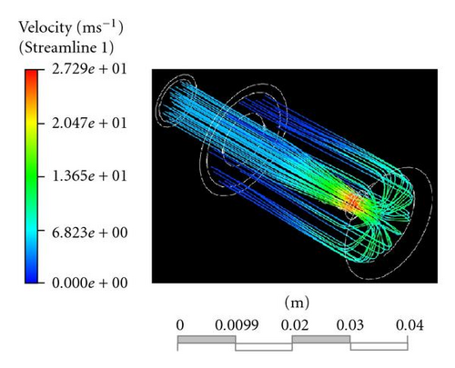
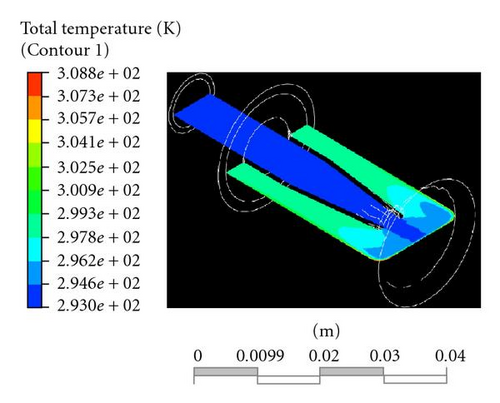
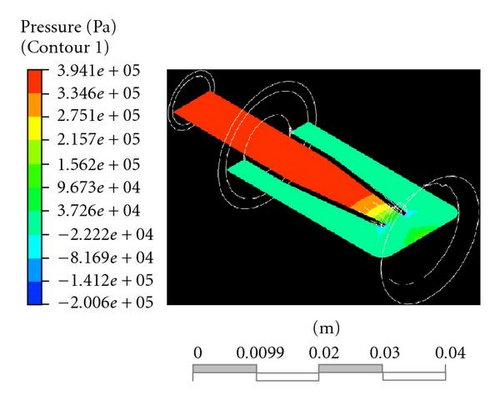
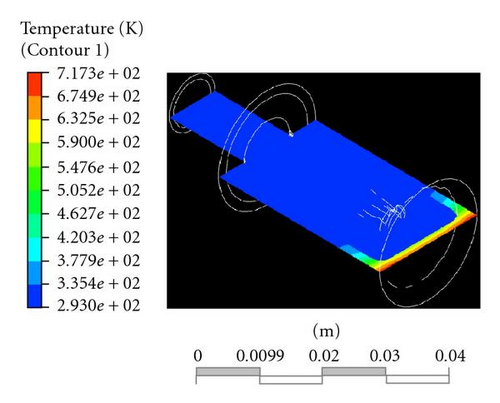
Figure 5(a) shows the fluid velocity stream lines. The inlet fluid velocity is 5 m/sec and increases up to 27 m/sec at the nozzle exit. Figure 5(b) shows the fluid temperature. The fluid temperature remains constant at the inlet value until impinging upon the target surface. After hitting the target surface, the fluid temperature increases and exits the rear of the target. A single jet nozzle produces a stagnation point at the impinging surface. The stagnation point is shown as bright green in Figure 5(c). The temperature distribution through the target body and the fluid is shown in Figure 5(d). The maximum temperature at the heated surface is 717 K.
The design of the impinging jet cooling system must satisfy two conditions: the maximum target temperature must be below the melting point, and the inward heat flux must be below the critical heat flux. In this target design, the target body is made of oxygen-free copper with a thin layer of molybdenum serving as the X-ray source. The melting points of molybdenum and copper are 2896 K and 1356 K, respectively, and hence the copper melting point is considered as the temperature limit. Figure 6 shows the maximum target temperature as a function of time for inlet water velocities of 3, 5, and 7 m/s. It is clear that increasing the coolant velocity decreases the target temperature. For example, increasing the coolant velocity from 3 to 7 m/s drops the maximum target temperature from 820 K to 650 K. But, the maximum target temperature exceeds the melting point of copper in 2 seconds at the inlet velocity of 2 m/sec. Figure 7 shows the coolant temperature at the stagnation point for the same three inlet velocities. Increasing the coolant inlet velocity also decreases the coolant temperature. For example, increasing the velocity from 3 to 7 m/s reduces the maximum coolant temperature from 318 K to 305 K. The critical heat flux depends on the coolant velocity at the nozzle and the temperature at the stagnation point. Figure 8 shows the predicted critical heat flux as a function of the coolant inlet velocity, where it is obvious that the critical heat flux increases with increased velocity.
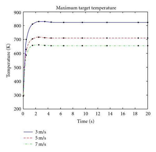

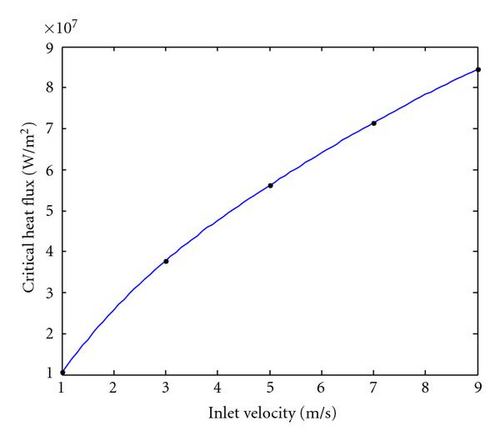
As seen from Figures 6, 7, and 8, the maximum target body temperature is reached in 2 seconds for all tested inlet velocities. In case of the 3 m/sec inlet velocity, the maximum temperature is 829.17 K. The critical heat flux at the same inlet velocity is computed to be 3.78 × 10⁷ W/m2. For an incident heat flux of 1.8 × 10⁷ W/m2, it can be inferred that boiling transition will not occur for a coolant inlet velocity of 3 m/sec. The calculations show that the minimum inlet velocity should be higher then 1.5 m/s to avoid boiling transition, but the inlet velocity should be higher than 2 m/sec to keep the target temperature below the melting point of copper.
5. Conclusion
Target cooling in the wide-beam X-ray source is a major design consideration due to the use of high beam current as compared to conventional X-ray sources. Passive cooling or rotating target geometry is not feasible for this wide-beam source design, and therefore, an active cooling system is required to satisfy the minimum operation time of about 20 seconds for a successful DEI scan. Previous studies of target cooling by liquid nitrogen-cooled cold fingers determined that cooling by conduction cannot provide better than 4 seconds operation with a 300 mA beam current [15], which is not sufficient to obtain the required DEI scan.
In this study, an active cooling system is proposed based upon an impinging water jet at atmospheric pressure. The prototype target design has been simulated using the finite element code ANSYS CFX. The simulations were performed with uniform inward heat flux and varying nozzle inlet velocity. Simulation results have shown that impinging jet cooling, with coolant inlet velocities in excess of 2 m/sec, allows for steady-state operation while satisfying all thermal design constraints.
Notation
-
- D:
-
- Surface diameter, m
-
- d:
-
- Jet exit diameter, m
-
- S:
-
- Exit-to-impingement distance, m
-
- q″:
-
- Heat flux
-
- Ja:
-
- Jacob number = (ρl/ρv)(CpΔTsub/hhg)
-
- ρ:
-
- Specific density, kg/m3
-
- hhg:
-
- Latent heat of vaporization, J/kg
-
- σ:
-
- Surface tension, N/m
-
- u:
-
- Exit velocity of liquid jet, m/s
-
- Cp:
-
- Specific heat at constant pressure, J/(kg K)
-
- T:
-
- Temperature, K
-
- Re:
-
- Reynolds number = ρl vs L/μ
-
- Nu:
-
- Nusselt number = h L/kf
-
- Pr :
-
- Prandtl number = ν/α
-
- L:
-
- Effective diameter, m
-
- vs:
-
- Mean fluid velocity, m/sec
-
- μ:
-
- Dynamic fluid viscosity, Pa·s
-
- h:
-
- Convection heat transfer coefficient, W/m2K
-
- kf:
-
- Thermal conductivity of the fluid, W/m K
-
- v:
-
- Kinematics viscosity = μ/ρ
-
- α:
-
- Thermal diffusivity = k/(ρ Cp)
Subscript
-
- v:
-
- Vapor
-
- l:
-
- Liquid
-
- sat:
-
- Saturation


