Mechanism and Comprehensive Prevention and Control of Damage Resulting From Dynamic Pressure on a Roadway of a Near-Vertical and Extra-Thick Coal Seam: Case Analysis of Wudong Coal Mine
Abstract
Aiming at the problem of large deformation and failure of the surrounding rock of the mining roadway in the nearly vertical and extra-thick coal seam group under the action of dynamic pressure, the deformation and failure mechanism of the mining roadway were analyzed based on the actual engineering conditions. Using the methods of in situ stress testing, physical composition analysis, and numerical simulation, the deformation and failure laws of the surrounding rock in the mining tunnel are expounded. The results show that the special geological structure and the bending and prying action of the middle rock column put the coal and rock mass in a high stress state, and the dynamic pressure disturbance aggravated the instability of the jointed and fractured surrounding rock in this high stress state. Using the method of transient electromagnetic testing, prevention and control measures such as deep hole pressure relief blasting and optimized mining sequence were determined, which effectively reduced the stress of the surrounding rock and weakened the impact of dynamic pressure on the stability of the tunnel’s surrounding rock. Field measurement and numerical simulation results show that the constant resistance large deformation active coupling support technology effectively improves the joint bearing capacity of the support structure and surrounding rock, and the deformation and damage of the surrounding rock in the tunnel are effectively prevented. Different engineering conditions have different damage characteristics of tunnel surrounding rocks, and specific problems should be analyzed in the prevention and control process. Although this result has achieved good application results in this project, it still has certain limitations. Some technical parameters are only applicable to this project or to situations with similar nearly vertical strata.
1. Introduction
Wudong coal mine is located in the southern margin of Junggar Basin, and its south mining area is the south wing of Badaowan syncline. Due to formation extrusion, the formation is nearly vertical and special occurrence. Near-vertical coal seams are often formed by strong geological movement. The local layer is even affected by multiple geological tectonic movements, forming folds and faults with large inclination angles in the regional structure, resulting in some strata even being upright or reversed. The residual structural stress in the strata is strong, and the coal mining stress environment is complex [1–4]. Near-vertical coal seams are widely distributed in western China, such as in the Urumqi mining area, which contains more than 30 layers of near-vertical (∼45°–87°) coal seams of different thicknesses and spacing [5–8]. Due to the influence of special tectonic movements, the deformation, failure, energy distribution, and stress transfer of the coal and rock layer have their own particularities [9–11]. Because Wudong coal seam is located in the two wings of Badaowan syncline, the mining roadway strike is consistent with the syncline axis strike, and the horizontal in-situ stress direction basically has a large angle with the syncline axis strike, so the angle between horizontal principal stress and the mining roadway is large, which has a great adverse effect on the stability of the surrounding rock of the roadway. In the case of thick coal-seam-topping coal mining, the mining space is large, the mining disturbances are violent, and the ore pressure is strong. Even in shallow mines, this still leads to serious deformation and damage to the mining hutch road [12–15].
Relevant scholars have studied the stability of near-upright and sharply inclined coal seam roadways. He et al. [16–19] according to engineering geology and nonlinear large deformation theory, the deformation law and the failure mechanism of key parts of roadway are emphatically analyzed, and the coupled support theory and the large deformation control technology are put forward. Yang et al. [20] used the three-dimensional distinct element code (3DEC) to numerically simulate a sharply inclined coal seam under excavation disturbance and carried out physical modeling experiments on the sharply inclined coal seam using an infrared monitoring system and AE monitoring system, which revealed the spatiotemporal evolution law of the dynamic instability characteristics of the sharply inclined coal mass under repeated disturbance. Zhang et al. [21] used the geodynamic zoning method and the characteristics of the original nearly upright extra-thick coal seam stress in combination to establish a hazard evaluation method for the ground pressure impact of a nearly upright extra-thick coal seam, which provided theoretical support for safe and efficient production in such mines. Ju and Li [22] analyzed the destruction characteristics of the old top of a horizontally segmented mine in a steeply inclined extra-thick coal seam, established a mechanical model for the fault of the cantilever beam along the inclined direction, and filled the gap in the theory concerning the mine pressure in steeply inclined coal seams. Through theoretical analysis, similarity simulation experiment, and numerical simulation, Li and Zhang [23] determined a reasonable stagger distance in the combined mining of a close-distance coal seam group in a large inclined coal seam and optimized the mining sequence and method. Wu et al. [24] studied the collapse mechanism of the roof along an empty alley in an inclined coal seam and concluded that, the larger the inclination angle of the coal seam, the longer the tangential slip distance of the top rock mass, the more serious the fracture development, the greater the degree of damage, and the smaller the amount of separation from the old top layer. Tu et al. [25] analyzed the impact of mining parameters on the mining stress of the working face of a large dip coal seam by numerical simulation. They found that the pressure relief state of the top and floor of the working face was asymmetrically distributed and proposed the idea of adopting the asymmetric support parameters of one lane and one scheme for the roadway support of the working face of the large dip coal seam. Wang et al. [26] studied the spatiotemporal evolution characteristics of dynamic instability of sharply inclined coal seams under dynamic loading and proposed a method to reflect the destructive nature of rock bursts in sharply inclined coal seams with characteristic displacement and acceleration parameters. By establishing the mechanical model and the elastic deformation energy equation of a steeply inclined cantilevered roof structure, He et al. [27] considered that the stress caused by high-pressure stress concentration and cantilevered roof failure is the most significant factor leading to rock burst in steeply inclined coal seams under goaf filling and proposed the pressure relief method of alternating deep and shallow hole blasting. Lv et al. [28] studied the factors influencing movement and deformation in the rock surrounding the long-wall working face with a composite filling in a steeply inclined coal seam and deduced the differential equation for roof deflection through a roof mechanic model. They highlighted that the deflection, bending moment, and rotation rate of the roof decrease with increases in the roof dip angle and filling ratio, whereas they instead rise with increases in the mining depth and working face length.
The research of related scholars has made great contributions to improving the stability control of steeply inclined coal seam roadways. However, there are few studies on the stability of mining roadways in nearly vertical and extra-thick coal seams. Based on the engineering geological conditions of the southern mining area in Wudong coal mine, this work studied the failure mechanism of the mining roadways and the stability control of the enclosing rock in the nearly upright extra-thick coal seams. Through on-site investigation, the in-situ stress test, and physical composition analysis of surrounding rock, combined with numerical simulation and other methods, the deformation and failure mechanism of surrounding rock is obtained. By reducing the surrounding rock stress, weakening the influence of dynamic pressure, optimizing the roadway excavation sequence, and adopting the constant resistance large deformation active coupling support technology, the coupling effect between the support body and the surrounding rock was strengthened, effectively improving the stability of the roadways surrounding rock.
2. Overview of Geology and Mining
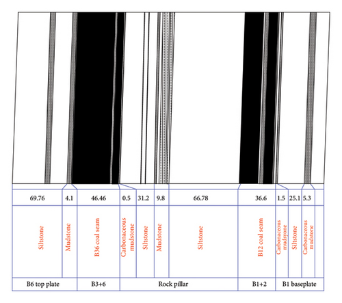
The southern mining area of Wudong coal mine is located in the south wing of Badaowan syncline in Urumqi. It belongs to the southward-inclined monoclinic structure. The inclination angle of the stratum is about 87°–89°. The average thickness of B1 + 2 coal seam is about 37 m, and the average thickness of B3 + 6 coal seam is about 48 m, as shown in Figure 1. Between the two groups of coal is a rock stratum with a thickness of 53–110 m. After the upper part of coal is mined, there are mined-out areas on both sides. The nearly vertical rock stratum forms an intermediate rock pillar. The length of each of the two working faces is 2520 m; B1 + 2 working face lags behind B3 + 6 working face by about 300 m. The coal adopts the horizontal, sublevel top-coal caving mining technology; the sublevel height is 25 m, the cutting coal depth is 3 m, and the caving height is 22 m, corresponding to top-coal caving mining with a large mining ratio. The upper, but not the entire, mined-out area of the mining level is backfilled with loess. The lower section of the mining roadway is simultaneously excavated. The mining roadway is arranged in the coal seam and excavated along the rock layer. In this study, the +475 mining level in the southeast mining area of Wudong was taken as the engineering background. The altitude of the area is +850 m, and the buried depth of the +475 mining level is 375 m.

3. Original Support and Deformation Characteristics
- 1.
The roadway deformation occurred quickly and is large in scale. When excavating a +450 level B6 roadway, the enclosing rock pressure is large, and the deformation of the two gangways of the hutch road in some sections reached more than 500 mm 6 days after excavation, while the subsidence of the hutch road shoulder reached about 430 mm.
- 2.
The deformation of the roadway is greater on the rock side than on the solid-coal side, and the degree of bottom heave is significant. The side-top angle of the coal body appears to sink and deform.
- 3.
The characteristics of roadway failure are dynamic. Microseismic events such as enclosing rock breaking and coal guns occurred frequently near the working face. These high-energy microseismic events were often accompanied by falling of coal cuttings, support failure, such as tray nuts falling, and even side bulge and sudden floor heave and U-steel crushing.
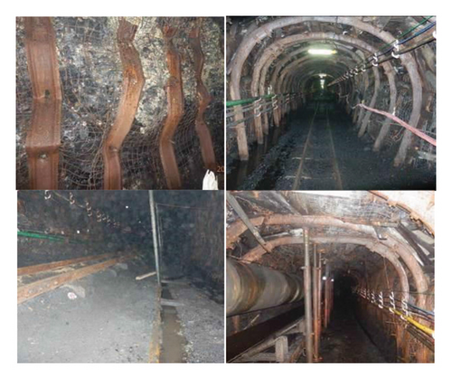
4. Analysis of the Roadway Deformation Failure Mechanism
4.1. Special Geomechanical Environment
4.1.1. Adverse Effects of Ground Stress
The mining area is located in the northern foot of Bogda Mountain in the piedmont fault-depression zone in the southern margin of Junggar Basin. It is found within the north and south wings of Badaowan syncline in the secondary fold fault zone of the secondary tectonic belt. The strong uplift of Bogda Peak and the orogenic movement of the Tianshan Mountains resulted in the strata of northern foothills of Tianshan Mountains being squeezed, giving them special characteristics. The mutual extrusion of the north and south strata causes Wudong coal mine to be a high-tectonic-stress area [29, 30]. The results show that the maximum horizontal principal stress σH is 15.19 MPa, the minimum horizontal principal stress σh is 10.38 MPa, the maximum vertical principal stress σv is 8.18 MPa, and the ground stress field belongs to the σH > σH > σv type. The maximum horizontal principal stress is 1.9 times the vertical principal stress, which shows that the ground stress in this area is dominated by horizontal tectonic stress. The direction of the measured maximum horizontal principal stress is N21.6° W, and the angle between the direction and the strike of the mining coal seam and the mining roadway is about 82°, which is close to vertical, which is extremely unfavorable for roadway stability. As the dip angle of the coal seam is close to vertical, the strike of the stratum is consistent with the strike of the syncline axis such that the direction of the maximum horizontal principal stress is close to the vertical direction of the rock stratum and the weak surface between the strata, which aggravates the instability of the enclosing rock of the roadway and the middle rock column, resulting in layered failure of the enclosing rock under shear force, as shown in Figure 3.

4.1.2. Bending Extrusion Effect of Near Vertical Rock Strata
When the B1 + 2 and B3 + 6 coal-seam groups are mined, a huge, nearly vertical intermediate rock pillar is formed between the two mined-out areas. Due to the vertical 3° dip angle of the strata in this area, the remaining B3 + 6 coal seam is overlaid with coal pillars, which have a pushing effect on the intermediate rock pillars. Therefore, under the action of self-weight and asymmetric horizontal pushing of the middle rock pillar, the upper part of the rock pillar bends and inclines to the B1 + 2 goaf, and the rock pillar deep into the lower part of the coal body will have a reverse bending effect, causing bending and prying extrusion to the coal body below the level of coal seam mining, causing the enclosing rock of the roadway to be in a high stress state. As the stratum is in a nearly vertical state, the roof and floor strata are inclined to the B3 + 6 and B1 + 2 goaf under the action of ground stress, which squeezes the coal seam.
To study the stress distribution, the numerical calculation model was established, and the x, y, and z lengths of the model are 676 m, 500 m, and 556 m, respectively. The upper boundary of the model is the ground, the horizontal displacement is fixed all around, and the vertical displacement is fixed at the bottom. The two groups of coal seams were excavated to the +475 level, and the gob was backfilled with soil. The formation material parameters are shown in Table 1. In order to obtain these material parameters, corresponding uniaxial and triaxial rock tests were carried out in the laboratory. The elastic modulus E and Poisson’s ratio v of the material were obtained through the uniaxial compression test of rock, so the shear modulus is G = E/2(1 + v) and the bulk modulus is K = E/3(1 − 2v) [31]. The cohesion and internal friction angle were obtained through the conventional triaxial compression test, and the tensile strength was obtained through testing and calculation using the Brazilian splitting test.
| Rock stratum | Lithology | Bulk modulus (GPa) | Shear modulus (GPa) | Density kg/m3 | Cohesion (MPa) | Internal friction angle (°) | Tensile strength (MPa) |
|---|---|---|---|---|---|---|---|
| B1 floor | Sandstone | 24.65 | 15.7 | 2590 | 6.59 | 36.31 | 2.9 |
| Middle rock pillar | Sandstone | 32.77 | 23.78 | 2783 | 5.92 | 30.84 | 2.34 |
| B6 roof | Sandstone | 21.32 | 13.82 | 2631 | 5.85 | 29.4 | 2.11 |
| B1+2 coal seams | Coal | 1.72 | 0.87 | 1410 | 2.26 | 25.14 | 1.13 |
| B3+6 coal seams | Coal | 1.68 | 0.91 | 1398 | 2.39 | 23.31 | 1.32 |
| Goaf fill | Fill soil | 0.0057 | 0.0019 | 1835 | 0.01 | 10.3 | 0 |
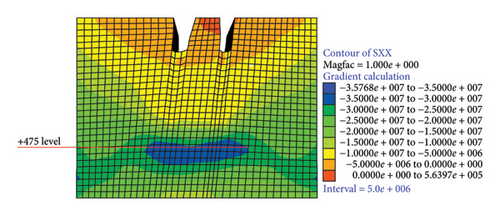
Through numerical analysis, the horizontal stress distribution is obtained. As shown in Figure 4, due to the bending, prying, and extrusion of the middle rock pillar, there is a clear horizontal stress concentration area in the mining level and below, stress concentration areas occurred within 50–70 m below the +475 level, and the horizontal stress reached approximately 35 MPa. Compared with the stress of the primary rock, the stress concentration coefficient reached 2.4. Stress was concentrated across two coal seam groups.
4.2. Poor Lithology of Roadway-Enclosing Rock
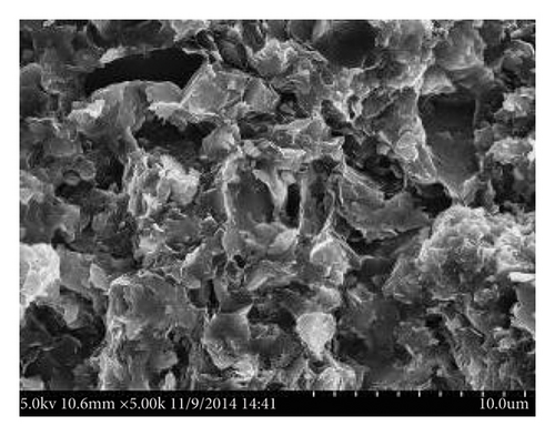
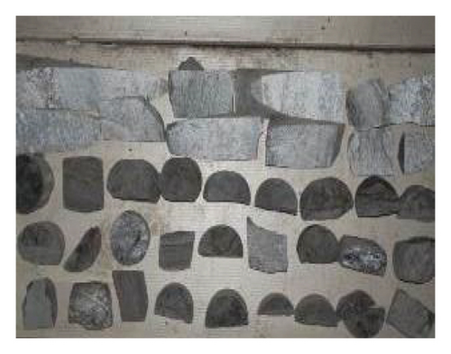
The dip angle of the strata in the southern area of the mine is 87°–89°, indicating a nearly vertical coal seam. The special environment and the mining method of horizontal segmentation cause the formation of a multilayered goaf space above the working face, and the mining roadway is arranged in the coal seam. As shown in Figure 1, the top of the roadway is the coal seam to be put in, the bottom is the lower coal seam, the top and bottom plates are all coal seams, and there are no hard top and bottom plates. Due to its low strength, weak bearing capacity, and fracture development, the overall stability is poor. One side of the mining roadway is rock. The enclosing rock on this side is generally 3–5 m mudstone or carbonaceous mudstone, and the deeper part of the enclosing rock is siltstone. The dissolution pores and fissures in the mudstone microstructure were analyzed by scanning electron microscopy (SEM). The siltstone is characterized by macroscopic joint fissures, and there are many weak planes in the rock, as shown in Figure 5, resulting in poor completeness and stability for the rock enclosing the roadway.
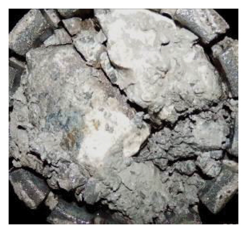
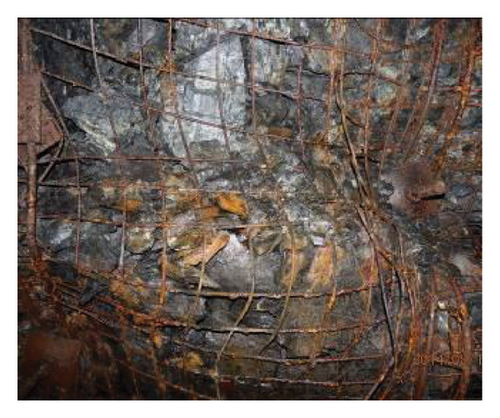
The results of the mineral composition test and the x-ray diffraction test show that the clay mineral content of mudstone on the B3 rock side is 54.3%, and the clay mineral content of mudstone in the enclosing rock of other roadways exceeds 50%. The water-absorbing mineral kaolinite accounts for 49%–59% of the clay minerals in the mudstone enclosing rock of each roadway, and the strong expansive mineral illite or montmorillonite mixed layer accounts for 40%–51%. Under the action of water, the connection between the mineral particles in mudstone will be destroyed, so that the water molecules will enter the layered particles, which will produce uneven stress and a large number of micropores in the rock, destroy the rock structure, and lead to the softening and disintegration of mudstone. The contents of clay and expansive minerals in mudstone are high, and the enclosing rock is easily weathered and softened or mudded and thus disintegrated when exposed to water. The roadway strata are prone to structural instability and large deformation of soft-rock expansion under the action of high stress and water. As shown in Figure 6, the surrounding rock undergoes disintegration and significant expansion due to water.
4.3. Influence of Dynamic Pressure
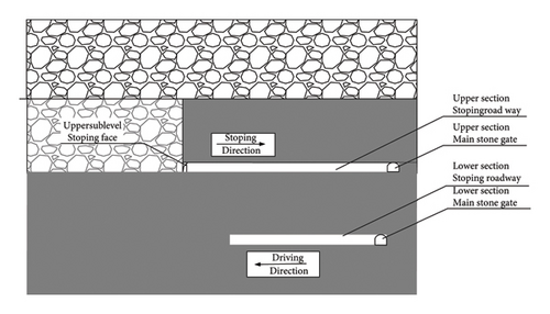
The mine adopts the horizontal-section, comprehensive, mechanized, top-coal caving mining technology: cutting coal in 3 m chunks and drawing 22 m, corresponding to a mining ratio of more than 1:7. The spatial relationship between the mining face and the lower section preparation roadway is shown in Figure 7. Due to the high hardness of top coal and the high height of coal caving, hydraulic support-lifting top pressure, coal-blasting vibration, and water injection are adopted in the mine to break and soften the coal seam in an attempt to improve the efficiency of coal caving and the recovery rate. This dynamic pressure has a significant adverse impact on the stability of surrounding rock in the lower subsection of the mining roadway, especially the coal blasting and the lifting and lowering of the top pressure of the support, which will directly act on the mining roadway in this subsection and the mining preparation roadway in the lower subsection and have a great impact on the stability of surrounding rock in the roadway.
When the cohesion c, internal friction angle φ, and support resistance P∗ of the enclosing rock are constant, the increase in the enclosing rock stress P0 will lead to an increase in the plastic-zone radius of the enclosing rock, which will lead to instability in the enclosing rock.
4.4. Failure Mechanism of the Original Supporting Structure
The support and enclosing rock should be coupled in strength, stiffness, and structure to achieve the most effective supporting effect [16]. The on-site damage of the roadway indicates that the original support and enclosing rock are not coupled. First of all, the strength of the initial support of the anchor cable is low, the prestress of the anchor cable is about 5 MPa, and the prestress of the anchor cable is about 10 MPa, which are not sufficient for providing the enclosing rock with enough active support. The failure of the enclosing rock in the structural plane cannot be effectively limited in time, resulting in further damage to the enclosing rock. Secondly, because the original supporting anchor cable and U-shaped steel are minor-deformation materials, they cannot effectively absorb the free energy added by the enclosing rock under stress disturbances and stress concentration, resulting in the expansion of the damage range to the deep rock. The plastic failure and interlayer separation of surface enclosing rock under high stress may lead to the overall instability of the roof and two sides. Thirdly, in the original support, the contact surface between the U-steel support and the roadway is small, mainly point contact. It cannot provide effective active support before the deformation of roadway-enclosing rock and cannot coordinate with enclosing rock during the deformation of enclosing rock, resulting in excessive deformation of local enclosing rock and then overall instability.
5. Comprehensive Prevention Countermeasures
- 1.
In view of the adverse effects of high crustal stress and bending extrusion of the rock column, the pressure-relief blasting method of the coal rock mass can be used to reduce the stress of the enclosing rock.
- 2.
In view of the disturbance of multiple mining in the upper and lower roadways, in order to prevent the disturbance stress in the upper and lower layers, the mining sequence can be optimized.
- 3.
For the problems of unreasonable support and mining influence during mining, the active coupling-support countermeasures of constant resistance and large deformation can be adopted to increase the support strength, absorb the energy of enclosing rock, improve the effect of active support and dynamic pressure protection, and help to achieve the purpose of successful roadway support.
5.1. Weakening the Enclosing Rock Stress Concentration
The maximum horizontal principal stress in the south mining area of the mine is perpendicular to the mining roadway strike. According to the relationship between the stress distribution and the stability of the enclosing rock, the crustal stress is extremely unfavorable for roadway stability. Therefore, deep-hole pressure-relief blasting of the enclosing rock was adopted to weaken the stress of enclosing rock and the bending stress of the middle rock pillar, reduce the stress concentration, alter the unfavorable stress environment, and eliminate or weaken the stress conditions of strong mining pressure [33].
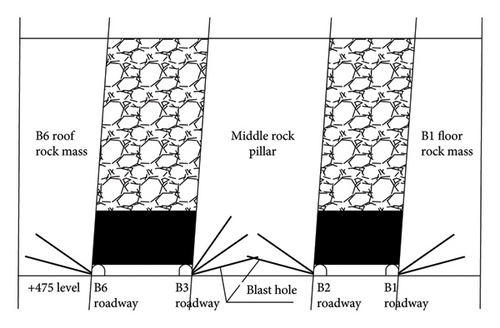
The blasting holes are arranged along the roadway in the rock sides of B1, B2, B3, and B6 roadways. The row spacing is 10 m, and two blasting holes with a diameter of 113 mm are arranged in each row, with angles of 15° and 35°, respectively. According to the depth of the stress concentration distribution area in the surrounding rock, the depth of blasting hole is 50 m, the length of charge is 30 m, and the length of the sealing hole is 20 m. Due to the bending and extrusion of the middle rock pillar, the rock side of the B3 roadway has a high degree of stress concentration, and the bending strain energy is stored in the rock mass. The enclosing rock is in an unstable state. To fully release the elastic energy of the enclosing rock and weaken the stress of the enclosing rock, three blasting holes are arranged in the rock side of the B3 roadway, and the angles are 15, 35, and 55°, respectively. The remaining parameters are consistent with the parameters of the blasting holes in the other three roadways, as shown in Figure 8.
5.2. Optimizing the Excavation Sequence of the Mining Roadway
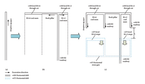
The mine uses a horizontal, sublevel, fully automated caving mining technique. In the original mining method, following completion of the arrangement of the upper sublevel working face, the main stone door was mined, and the next sublevel’s excavation roadway was excavated from the main stone door to the open-off cut direction. This inevitably caused mining in opposite directions, resulting in a service period to address multiple dynamic pressure disturbances and roadway maintenance difficulties. After optimization and adjustment, the B2 roadway with less problematic enclosing rock conditions was excavated first, as shown in Figures 9(a) and 9(b). After the B2 tunnel is excavated to the open-off cut, auxiliary stone gates are excavated to the innermost positions of the other three roadways, and then, these three tunnels are excavated outward and in the direction of the main stone gate—that is, it underwent reverse excavation, and the other three roadways lag behind the upper working face by a certain distance of about 100 m, as shown in Figure 9(c). This allows not only avoiding the problem of mining in opposite directions but also avoiding the roadways with poor enclosing rock conditions due to being affected by the disturbances of upper-layer mining, which will greatly improve the roadway stability.
5.3. Constant-Resistance, Large-Deformation Active-Coupling Support
5.3.1. Constant-Resistance, Large-Deformation Anchor Cable
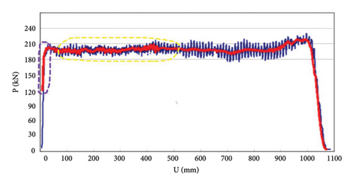
In view of the fact that the traditional anchor cable is a strain-hardening material, its elongation deformation is small, and it is prone to necking or even breaking after stretching, which means it cannot meet the requirements of large deformation of the enclosing rock, especially regarding the stability control of the enclosing rock of a dynamic-pressure roadway. Based on the concept of constant resistance and energy absorption, researcher Manchao He invented a constant resistance large-deformation anchor cable. It comprises a rod body or steel strand, a constant resistance device, and a tray [34, 35]. It has the mechanical properties of basically maintaining ideal elastic plasticity in the deformation range and being able to maintain high constant support resistance while having a pressure effect on the enclosing rock of a large-deformation roadway. In the field, the constant-resistance value of a constant-resistance bolt can reach 200 kN and has a slip elongation of 300 mm (reaching 1000 mm under laboratory conditions), and the constant-resistance value of a constant resistance anchor cable can reach 350 kN and has a slip elongation of 300 mm. Figure 10 shows the mechanical performance curve of the constant-resistance bolt.

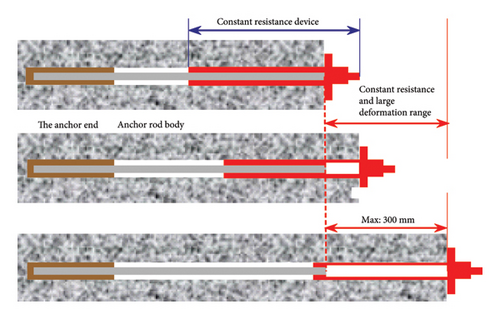
The constant resistance large deformation bolt consists of a constant damper (constant resistance large deformation device) and a rod body. In the early stage of support, when the load of surrounding rock on the bolt exceeds the damper threshold, the sliding between the bolt and the damper occurs, thus absorbing the deformation energy of surrounding rock. At the same time, because the constant resistance bolt can provide high working resistance in real time, it can effectively limit the excessive damage and deformation of the surrounding rock. When the load of surrounding rock is reduced below the constant resistance value, the bolt stops extending, the surrounding rock-support system is in equilibrium again, and the overall stability of the roadway is realized. The working principle of the constant-resistance large-deformation anchor rod is shown in Figure 11.
5.3.2. Active-Coupling-Support Principle
- 1.
Strength coupling. The stress of the enclosing rock changes from being in three directions to being in two directions after roadway excavation. At this time, if there is no reasonable support measure on the free face, under the action of secondary stress and excavation stress concentration, the failure range of enclosing rock extends to the deep layers, forming a large range of broken zones and plastic zones. The prestress of the constant-resistance bolt can reach 150 KN, and the prestress of the constant-resistance anchor cable (steel strand diameter of Φ21.8 mm) can reach 280-300 KN. The three-dimensional support of a high-strength constant-resistance anchor cable can strengthen the broken enclosing rock; lock the broken zone, plastic zone, and elastic zone of enclosing rock as a whole; improve the internal friction angle and cohesion of enclosing rock to improve the stress state of enclosing rock; and truly realize the active support of the anchor cable, so as to improve the overall strength of the enclosing rock. For a roadway experiencing strong dynamic disturbances, it is necessary to improve the antidisturbance ability of the enclosing rock and enhance the stability of the enclosing rock.
- 2.
Stiffness coupling. Stiffness coupling is the key to coupling support. It is required that the support body has sufficient flexibility to allow the enclosing rock of the roadway to produce a certain amount of variable release energy. The support body should also be stiff enough to keep the road’s enclosing rock within the range of permitted deformation. In the past, stiffness coupling was mainly used to increase the deformation of anchor cables by means of wooden pallets or reducing the support strength, and the effect was often not ideal. Constant-resistance, large-deformation anchor cables can maintain high strength support at the same time as appropriately yielding to deformation of the enclosing rock. After roadway excavations, the constant-resistance anchor cable is supported by high prestress. When the deformation–expansion force of the enclosing rock exceeds the constant resistance value, the constant-resistance anchor cable generates tensile deformation to release the pressure on the enclosing rock and absorb the deformation energy. When the enclosing rock pressure is less than the constant resistance value, the anchor cable stops tensile deformation, as shown in Figure 10. The interaction between the enclosing rock and support is automatically realized in this process, so it is generally not necessary to consider the secondary support time to realize automatic stiffness coupling. In the process of interaction between the enclosing rock and the supporting body, the free energy caused by the dynamic pressure of the enclosing rock is absorbed to avoid the excessive deformation and damage to the enclosing rock so as to realize support integration and load homogenization.
- 3.
Structural coupling. A constant-resistance, large-deformation anchor cable has the mechanical properties to support extensive deformation such that it can increase the initial support resistance and thereby has a good reinforcement effect on the discontinuous surface of the enclosing rock mass. The discontinuous deformation of the discontinuous surface and the support body is limited by the combined reinforcement of the constant-resistance anchor cable, and the roadway damage caused by local excessive deformation is reduced. For a nearly vertical dynamic-pressure roadway, the friction strength and cohesion of the structural plane are increased, and the stability of the enclosing rock is improved.
5.3.3. Support Scheme
- 1.
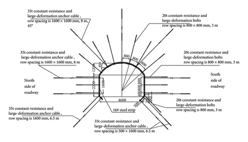
The cross-section of a constant-resistance anchor cable adopts a 350 KN constant-resistance, large-deformation anchor cable with a diameter of Φ21.8 mm. Three constant-resistance, large-deformation anchor cables are used at the top of the roadway. The angle between the anchor cables on both sides and the horizontal direction is 45°, and the length is 8000 m. Two anchor cables with constant resistance and large deformation are used on each side, with a length of 6500 mm and a row spacing of 1600 × 1600 mm. The bottom angle is supported by an asymmetric anchor cable, and the side bottom, for which the angle makes the structure prone to floor heave and strong mine pressure, is supported by two constant-resistance anchor cables with row spacing of 500 × 1600 mm, and the other side bottom is supported by one anchor cable, which is at an angle of 45° with the floor.
- 2.
Constant-resistance bolts are used: 200 kN constant-resistance, large-deformation bolt, with a diameter of Φ22 mm and a length of 3000 mm. Seven constant-resistance bolts are used on the top, and three 200 kN constant-resistance bolts are used on the two sides. The bolts are connected by trapezoidal steel strips. The row spacing between the bolts at the top is 800 × 800 mm, and one constant-resistance bolt is used at each bottom corner.
- 3.
protecting material uses a Φ16 mm, trapezoidal, steel connecting anchor cable and metal mesh to improve the ability of protecting. The roadway support section is shown in Figure 12.
6. Prevention and Control Effect
6.1. Relief of Pressure due to Blasting
The transient electromagnetic method analyzes the integrity of the enclosing rock by detecting the apparent resistivity characteristics of the enclosing rock. The presence of cracks in coal and rock mass will change its electromagnetic properties. The transient electromagnetic method has a high resolution for resistivity changes, and resistivity changes caused by cracks can be easily detected. At the same time, the transient electromagnetic method has the characteristics of high efficiency, high resolution, and easy operation. Therefore, this method is used to evaluate the effect of pressure relief blasting. When the surrounding rock is complete and dense, the apparent resistivity is small, and when the surrounding rock has more cracks, the apparent resistivity is bigger [36]. So, the transient electromagnetic method is used to test the weakening effect of blasting on rock mass. Figure 13 shows the distribution of apparent resistivity before and after blasting of the middle rock pillar at 800 m of the B3 track roadway. As the transient electromagnetic instrument has “blind depth” in the detection, according to the actual detection data, it was determined that the effective detection depth is within 20–100 m of the detection surface.
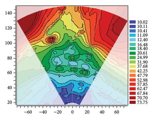

Figure 13(a) shows the distribution of apparent resistivity before blasting. It can be seen in the figure that the apparent resistivity is 10–25 Ω • m in the range of 20–100 m, and the distribution is relatively uniform, indicating that the rock mass is complete and dense in this range.
Figure 13(b) shows the apparent resistivity after blasting. It can be seen in the figure that high-resistivity anomalies appear in the rock strata in the range of 20–70 m, and the apparent resistivity is between 30 and 86 Ω • m, which classifies these zones as high resistivity, and they are connected to each other. Comparing the apparent resistivity distribution before and after blasting, it can be seen that the apparent resistivity of the rock mass in the detection area changed significantly, indicating that blasting caused loose fracturing of the rock mass and achieved the effect of weakening the stress of the loose enclosing rock. At the same time, the enclosing rock failure zones formed by each blast hole are connected and overlapped, which indicates that the interval of 10 m is reasonable and can produce a continuous weakening effect on the rock pillar.
6.2. Numerical Analysis of Constant-Resistance Active-Coupling Support
In order to test the effect of active-coupling support with constant resistance and large deformation capabilities, a three-dimensional geomechanical model was established using FLAC3D software. The numerical model is composed of hexahedral elements, and the calculation range is 50 m × 50 m × 30 m. The geological model is shown in Figure 14.
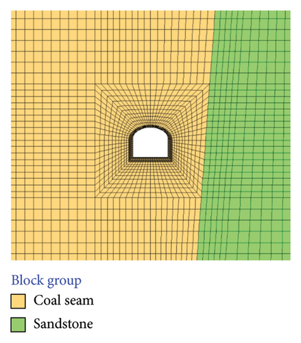
The side of the model is limited to horizontal movement, the bottom is fixed, the upper surface of the model is the stress boundary, which is about 9 MPa, the stress boundary is assigned according to the relevant data of the ground stress test, and the Mohr–Coulomb strength criterion was used for the failure of the surrounding rock material. The default convergence standard of FLAC3D is adopted; that is, when the ratio R between the maximum unbalanced force and the typical internal force of the system is less than the fixed value 1e − 5, the equilibrium is considered to be reached. The mechanical parameters of each rock stratum are determined based on laboratory test results, as shown in Table 1. In FLAC3D, the anchorage strength of the end of the anchorage section of the constant-resistance, large-deformation bolt needs to be 20% higher than the tensile strength of the bolt. The end of the free section is in rigid contact with the enclosing rock to simulate the tray. Fish language was used to judge the relative displacement between the free end and the anchorage end and to monitor the change in the axial force. When the constant resistance value is reached, axial tensile deformation is produced to achieve the effects of constant resistance and large deformation so as to simulate the constant resistance and large deformation bolt.
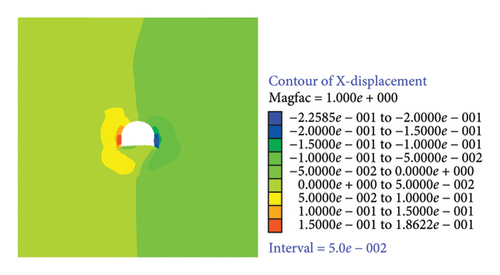
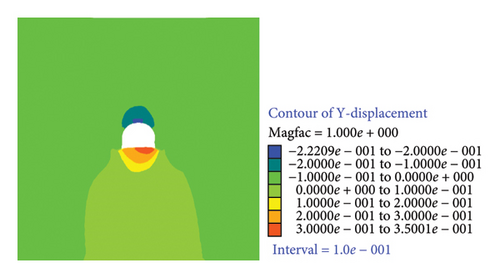
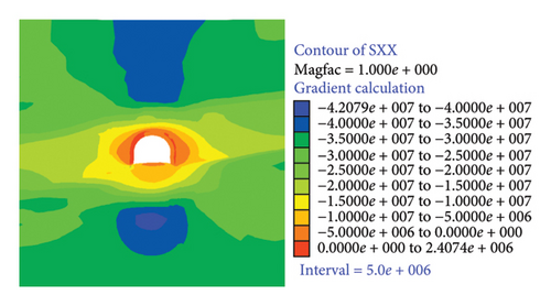
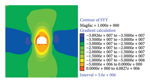
Constant-resistance, large-deformation supports allow the effective control of the deformation of enclosing rock in the roadway of an extremely thick, nearly vertical coal seam. As shown in Figures 15 and 16, the deformation of the left side of the roadway is about 160 mm, the deformation of the right side is about 200 mm, and the maximum deformation of the sides is about 80% lower than that of the original support. The maximum subsidence of roof is about 200 mm, and the maximum deformation of floor is 300 mm. The overall displacement of the roadway-enclosing rock is small, and the deformation is kept within the maximum tensile values of the constant-resistance, large-deformation supports. It can be seen in the stress-cloud diagram that the stress distribution of the enclosing rock of the roadway is uniform, which greatly reduces the stress concentration area, and there is no stress overrelaxation area. As the new support can maintain the characteristics of constant resistance and large tensile deformation, the enclosing rock can slowly deform and therefore slowly release the deformation energy during the interaction between the new support and the enclosing rock. The new support can absorb the deformation energy through the sliding of the constant resistance device, which can allow avoiding the destruction of the enclosing rock of the roadway due to mining disturbance through improving the stress state of the enclosing rock and increasing the overall strength of the enclosing rock, resulting in effective control of the stability of the enclosing rock of the roadway.
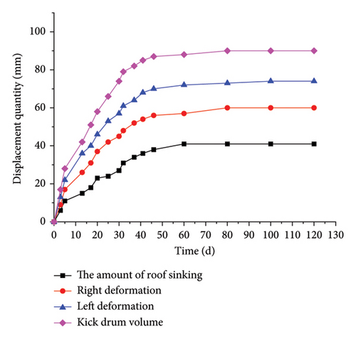
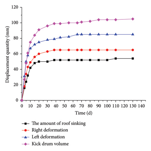
In order to observe the deformation of the enclosing rock of the new support, two monitoring stations were arranged in the new support roadway, which are Stations I and II, as shown in Figure 17. From the observation curve, it can be seen that the roadway supports are in good condition, the maximum shrinkage of the two sides is 84 mm, the maximum floor heave is 104 mm, and the maximum top settlement is 41 mm. Thus, the deformation of the enclosing rock is effectively controlled within the allowable deformation range of the project. According to the observation of enclosing rock deformation, the deformation of roadway-enclosing rock mainly experiences three stages: severe deformation ⟶ slow deformation ⟶ stability. Within 10–18 days after roadway excavation and support, some energy due to the large rock press was released under the constant working resistance of the constant-resistance and large-deformation bolts/cables, and the deformation was severe. During the monitoring period of 18–45 d, the stress distribution of enclosing rock was constantly adjusted and tended to be uniform, and the deformation of the enclosing rock slowed down due to the high supporting resistance of the constant-resistance and large-deformation anchor cable. After about 50 days, with the full release of enclosing rock’s expansion energy and plastic energy, the load acting on the bolts and cables was reduced to below the constant resistance values, and the roadway remained stable.
7. Conclusion and Discussion
7.1. Conclusion
- 1.
The deformation and failure mechanism of a dynamic-pressure roadway in a near-vertical, extra-thick coal seam were analyzed through field investigation, in situ stress testing, numerical calculations, and physical and chemical composition tests of the enclosing rock. It was considered that the special geological structure and the bending and prying action of the middle rock column place the coal and rock mass in a state of high stress, and the dynamic pressure disturbance aggravates the instability of the jointed, fractured enclosing rock under this high stress state. At the same time, there is excessive roadway deformation due to the low strength of the original supports and the uncoupling of the enclosing rock mass.
- 2.
The method of surrounding-rock deep-hole pressure-relief blasting and optimization of the mining sequence was adopted to weaken the enclosing rock stress and the bending stress of the middle rock column, so as to avoid or reduce the adverse effects of multiple dynamic pressures, alter the adverse stress environment, and eliminate or weaken the stress conditions caused by high rock pressure.
- 3.
With the aim of addressing the problems of crack development and large deformation failure of original supports in roadway-enclosing rock under dynamic pressure, the active-coupling support technology with constant resistance and large deformation tolerance was adopted to effectively reinforce the enclosing rock and absorb excess energy, in which joint bearing of the support and enclosing rock is realized and increases the overall strength of the enclosing rock. The numerical analysis results demonstrate that the stability of the enclosing rock is achieved.
7.2. Discussion
Taking the south mining area of Wudong coal mine as an example, this paper studies the deformation and failure mechanism of surrounding rock in the mining roadway of near vertical coal seam. Prevention and control measures such as deep hole pressure relief blasting and optimization of the mining roadway excavation sequence are taken to reduce the stress concentration of surrounding rock and weaken the influence of dynamic pressure on surrounding rock. At the same time, the active coupling support technology of constant resistance and large deformation is adopted to effectively improve the stability of surrounding rock. Through comprehensive technical measures, the problem of large deformation of surrounding rock in the near-vertical coal seam mining roadway is well controlled in practical engineering. Although this result has achieved good application results in this project, it still has certain limitations. For example, (1) some technical parameters are only applicable to this project or to situations with similar nearly vertical strata. (2) In the numerical simulation of the support scheme, the Mohr–Coulomb model is adopted as the geotechnical constitutive model, which is a medium ideal elastoplastic model, and the calculation results are conservative. Therefore, more attention should be paid to the construction quality and deformation failure monitoring in the practical engineering application, and the support should be further strengthened when the deformation is large.
Conflicts of Interest
The authors declare no conflicts of interest.
Funding
This study was supported by the National Natural Science Foundation of China (no. 51604093), the Henan Provincial Talent Training Joint Fund (no. U1204509), and the Henan Natural Science Foundation Project (no. 222300420596).
Acknowledgments
This study was supported by the National Natural Science Foundation of China (no. 51604093), the Henan Provincial Talent Training Joint Fund (no. U1204509), and the Henan Natural Science Foundation Project (no. 222300420596).
Open Research
Data Availability Statement
The authors confirm that the data supporting the findings of this study are available within the article.


