Study of the System of Forces Acting on the Cutter-Oscillator Under Conditions of Turning With Vibration
Abstract
This paper investigates the forces acting on a cutter-oscillator during free longitudinal orthogonal turning under regenerative self-oscillation conditions. The cutter-oscillator had single degree of freedom in the direction of cutting thickness variation, while the workpiece was rigid and made of AISI 1045 steel. Cutting parameters such as cutting speed, feed rate, and depth of cut, as well as the cutter-oscillator’s additional mass, were varied. Two main groups of forces influencing the cutter-oscillator were identified. The first group consists of cutting forces generated during chip formation and friction between the tool edge, chip, and cutting surface. These forces depend on the equilibrium between the shear plane and the tool’s contact surfaces. The second group arises from the dynamic behavior of the cutter-oscillator and includes elastic, inertial, and damping forces. These are governed by the cutter-oscillator’s mass and its response to cutting loads. An important feature of the system is the mutual interaction between these force groups, forming feedback loops that complicate analysis and control. Under regenerative self-oscillations, the cutter-oscillator’s deflections are affected by a combination of forces whose individual contributions cannot be isolated. As a result, conventional dynamometers, which have their own elastic properties, are unsuitable for capturing the true dynamics of the cutting process in such conditions. Cutter-oscillators, by contrast, provide a more accurate representation of the cutting forces under self-oscillation. The oscillogram of the cutter edge deflection serves as a reliable and reproducible indicator of both static and dynamic cutting conditions. This approach aids in better understanding of the process mechanics, contributes to the optimization of cutting parameters, and enhances overall manufacturing efficiency.
1. Introduction
The study of the dynamics of the cutting process and the resulting forces is one of the key tasks in the field of metal machining and mechanical engineering. Forces acting on cutting tools directly affect the quality of machining, dimensional accuracy, tool wear resistance, and economic efficiency of production processes. Therefore, predicting cutting forces is an essential part for optimizing the cutting process.
In order to effectively analyze such processes, it is necessary to understand the nature of the occurrence of dynamic forces, as well as to possess methods of their accurate measurement and control. The dynamic nature of forces during cutting occurs in the presence of vibrations. The main type of vibration during turning is regenerative self-oscillation (SO), which occurs under conditions when there is waviness in the longitudinal section of the cut layer on the free cutting surface from the previous revolution of the part. In the presence of a phase shift between the waves on the cutting surface during the previous and current revolutions of the part, an oscillation in the thickness of the cut allowance occurs, which is the source of the regenerative SO.
2. Literature Review
The most convenient scheme for studying regenerative SO during turning is the scheme of free orthogonal cutting [1]. The condition of free orthogonal cutting is convenient in that in the orthogonal plane, located perpendicular to the direction of the cutting edge (CE), the system of forces is flat and the same for each point of CE. Let us consider the system of forces for this turning scheme (Figure 1), in which the part will be considered absolutely rigid, and the cutter will act as an oscillator. To simplify the system of forces, we will use a cutting insert with a rake angle equal to 0° and the principal approach angle of the CE equal to 90°.
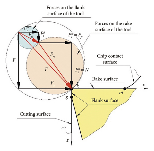
To study cutting as a physical process, the system of forces is considered separately: only on the rake surface, due to the process of chip formation, and on the flank surface, due to its friction with the cutting surface [6]. The forces acting on the cutter from the flank surface Ffs are significantly less than the forces acting on the rake surface of the cutter Frs. Moreover, the actions of these forces are independent of each other. Therefore, to simplify the system of forces, the cutting force on the flank surface Ffs is usually not taken into account (F = Frs). It role becomes significant only in cases of cutting with small cutting thicknesses.
To study the forces acting on the cutter under vibration cutting conditions, numerical and analytical methods [7, 8], modeling, artificial intelligence technologies [9, 10], and experimental methods [11, 12] are used. In experimental studies, dynamometers of different designs are used to study forces [12, 13]. Cutting forces have good sensitivity to vibration. Modern designs of dynamometers for measuring the components of cutting forces Fx, Fy, and Fz allow these measurements practically eliminating the mutual influence of forces on different axes [14]. However, due to their complex design, the dynamometers reflect their own elastic system (ES) in the investigation rather than the cutting process [15].
The most suitable devices for investigating cutting forces under regenerative SO conditions are single-degree-of-freedom (SDOF) cutter-oscillators, whose direction of force measurement aligns with the direction of change in shear thickness (x-axis) [15, 16].
However, despite the extensive body of research dedicated to the dynamics of the cutting process under regenerative SO conditions, many studies have not sufficiently addressed the simplification of the ES of the cutter-oscillator in order to constrain its vibrations solely to the direction of variation in chip thickness—the primary source of regenerative SO. Such simplification makes it possible to isolate the specific force system responsible for exciting vibration of the cutter-oscillator in that direction.
On the other hand, the measurement instruments used in existing studies to investigate the dynamic components of the forces acting on the cutter-oscillator often fail to provide the required level of accuracy and data reproducibility.
The objective of this study is to analyze the force system responsible for the oscillations of SDOF cutter-oscillator during turning under conditions of regenerative SO.
The scientific novelty of this work lies in the assessment of the contribution of each component of the force system to the overall dynamics of the cutting process, as well as in the establishment of an objective and accurate method for measuring the dynamic component of all types of forces acting on the cutter-oscillator during turning under regenerative SO conditions.
3. Analysis of the System of Forces Acting on a Cutter-Oscillator With SDOF
Figure 2 shows the scheme of forces, in the orthogonal plane (πO) in free orthogonal cutting, proposed by Merchant [17, 18] and studied in detail by Zorev [19]. The physical basis of this scheme is the position of the chip equilibrium between the acting forces on the conventional shear plane kn with length l and the contact surface of the chip with the tool km with length C (Figure 2). The stress-strain state of the chip-forming zone is assumed to be flat. Therefore, increasing the width of the cut layer a, located along the CE (point k), proportionally increases the chip-forming force Frs = F, but does not change the stress-strain state at each point of the CE. In order to maintain the chip equilibrium conditions, equal forces with opposite directions act on the chip from both sides. Shear force Fs and normal force Fn act in the shear zone, and friction force Ffr and normal force N act in the tool contact zone.
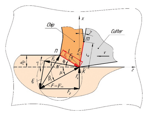
If the system of forces shown in Figure 2 is applied to a cutter-oscillator, which is absolutely rigid, i.e., immobile from the action of forces in the chip-forming zone (Figure 3(a)), then reactions Rx and Rz, equal to the forces Fx and Fz, but oppositely directed, appear at the points where the cutter-oscillator is fixed.
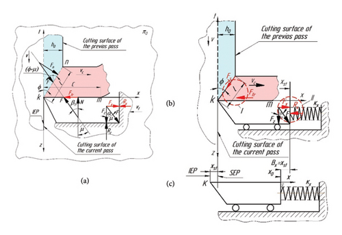
Under static loading, the deformation of an elastic element of the cutter-oscillator is related to the loading force by Hooke’s law [20]. From Figure 3 shows that the CE (point k) of the cutter-oscillator has two equilibrium positions. Initial equilibrium position (IEP) (Figure 3(c)), when there is no cutting process. The of static equilibrium position (SEP) (Figure 3(b)), when the forces Fx and Fz act on the cutter-oscillator during the cutting process, but the CE is displaced only along the x-axis by the value xst = Bx (Bx—static deflection of the cutter-oscillator), since there is only SDOF.
Figure 3(a) shows that the force Fx and the reaction Rx change according to different laws when the cutting thickness h changes and the cutting edge moves along x.
Figures 4(a) and 4(c) show that the zero value of the reaction of the cutter-oscillator Rx = 0 starts from the IEP and increases in proportion to the increase in its displacement along the x-axis during cutting until the equilibrium between Fx and Rx, i.e., the SEP, occurs.
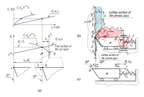
The zero value of the force Fx = 0 is located at the point of contact of the CE (point k) with the free surface of the layer to be cut and increases according to the power law with the increase of the cutting thickness h. Thus, it can be stated that during cutting, there are two zones in which the conditions of force equilibrium are maintained (Figures 4(b) and 4(c)): the zone between the shear plane and the contact surface of the cutter and the zone between the force Fx and the elastic reaction Rx.
During continuous cutting along the “vibration trace” (Figures 4(b) and 4(c)) on the cutting surface, chip formation occurs as a result of shear deformations under the shear angle ϕ along the length l, as well as during cutting without vibration (Figure 2). However, in the presence of a wave on the cutting surface from the previous revolution, the length of the shear plane will be variable and therefore the force Fs in the shear plane calculated by equation (5) will also be variable [23].
It has been experimentally established that the frequency of oscillation of the length of shear plane is equal to the frequency of oscillation of CE of the cutter-oscillator along the x-axis [23]. Therefore, the shear force Fs will also oscillate with frequency . Based on the statement about the preservation of the chip equilibrium condition, we can assume that the force Fx will also start oscillating with frequency , but with some delay. The oscillation of force Fx should cause the oscillation of cutter-oscillator reaction Rx. But since the moving cutter-oscillator has a mass, there are additional inertia forces and damping forces , at the appearance of which the conditions of static cutting become dynamic.
4. Materials and Methods
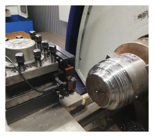
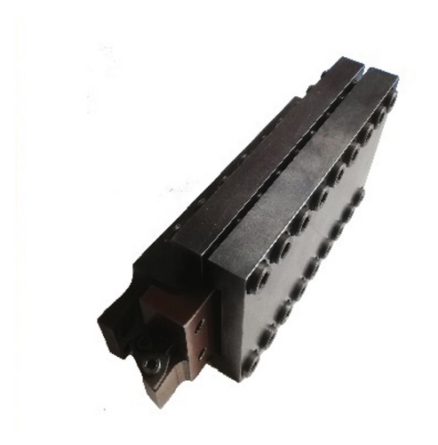
The forces acting on the cutter-oscillator were investigated during longitudinal turning of a rigid part made of AISI 1045 steel (Figure 5). The research was carried out on a CNC lathe mod. Zenitech WL 320 (Figure 6(a)). The design of the cutter-oscillator (Figure 6(b)) provided for the possibility of installing an additional mass to the head of cutter-ocsillator to change the natural frequency of oscillation in the range from f = 150 to f = 1250 Hz.
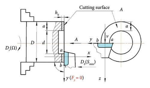
During turning process, the cutting modes were varied: cutting speed v = 100…300 m/min, feed S = h0 = 0.1…0.3 mm/rev, and depth of cut t = a = 1…2 mm. The cutting insert had a principal approach angle of φ = 90°, a rake angle of γ = 8°, and a clearance angle of α = 8° and was made of HS123 carbide.
The cutter-oscillator with SDOF provided movement of CE in the direction that coincided with the direction of the force Fx [15]. The displacement of CE was measured with a Schneider Electronics XS4-P12AB110 sensor. The analog-to-digital converter mod. LCard E14-0 converted the sensor signal into a digital oscillogram form and transmitted it to a personal computer (Figure 7).
5. Results
5.1. Results of Investigation of Inertia Forces Under Cutting Conditions With Vibration
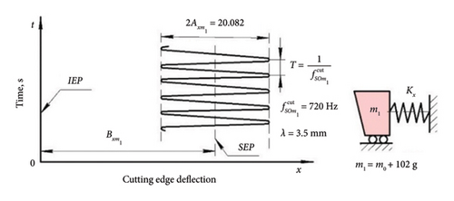
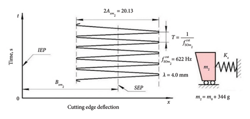
In the course of experimental studies, the results of the influence of the mass of the cutter-oscillator on its dynamic behavior (50 experiments for each value of additional mass) were obtained. The turning was carried out at a constant cutting speed corresponding to the regenerative SO zone. The width of the flank surface wear area was kept in the range of 0.10…0.15 mm to ensure constant damping conditions. Additional weights m1 = 102 g and m2 = 344 g were attached to the head of the cutter-oscillator. The stiffness of the cutter ES was constant in all cases. The experimental results are summarized in Table 1 and Figures 8 and 9.
| Additional mass, m, g | Diameter D, mm | Spindle speed, Ω, rpm | Static deflection, Bx, mm | Amplitude, Ax, mm | Frequency , Hz | Wavelength, λ, mm |
|---|---|---|---|---|---|---|
| 0 | 132.5 | 360.4 | 0.082 | 0.051 | 762.7 | 3.3 |
| 0 | 120.5 | 396.2 | 0.08 | 0.061 | 772.3 | 3.2 |
| 0 | 106.5 | 448.3 | 0.081 | 0.07 | 769.2 | 3.3 |
| 0 | 78.5 | 608.2 | 0.079 | 0.075 | 769.8 | 3.3 |
| 0 | 44.5 | 1073 | 0.077 | 0.077 | 767 | 3.3 |
| 102 | 128 | 373 | 0.074 | 0.084 | 722 | 3.5 |
| 102 | 102 | 468.1 | 0.075 | 0.078 | 716.9 | 3.5 |
| 102 | 80 | 596.8 | 0.078 | 0.081 | 724.8 | 3.5 |
| 102 | 44 | 1085.1 | 0.078 | 0.082 | 720.1 | 3.5 |
| 102 | 30 | 1591.5 | 0.078 | 0.084 | 711.5 | 3.5 |
| 344 | 132.5 | 360.4 | 0.079 | 0.093 | 594.5 | 4.2 |
| 344 | 112.5 | 424.4 | 0.077 | 0.095 | 593.9 | 4.2 |
| 344 | 94.2 | 505.3 | 0.079 | 0.093 | 622.1 | 4 |
| 344 | 56.5 | 845.1 | 0.075 | 0.11 | 617.9 | 4.1 |
| 344 | 32.5 | 1469.1 | 0.074 | 0.107 | 631.9 | 4 |

5.2. Results of Investigation of Friction Forces on the Flank Surface of the Cutter-Oscillator Under Cutting Conditions With Vibration
The results of the experimental study of the influence of friction forces on the flank surface of the cutter-oscillator on the dynamics of the cutting process are presented in Table 2 and Figure 10.
| Cutting speed, v, m/min | Width of the wear area on the flank surface, hf | |||
|---|---|---|---|---|
| 0–0.05 mm | 0.1–0.15 mm | 0.25–0.25 mm | 0.3–0.5 mm | |
| 50 | 0.016 | 0.007 | 0.006 | 0.000 |
| 75 | 0.028 | 0.014 | 0.012 | 0.001 |
| 100 | 0.038 | 0.020 | 0.014 | 0.002 |
| 125 | 0.053 | 0.026 | 0.018 | 0.003 |
| 150 | 0.067 | 0.036 | 0.021 | 0.003 |
| 175 | 0.084 | 0.042 | 0.025 | 0.005 |
| 200 | 0.100 | 0.050 | 0.028 | 0.006 |
| 225 | 0.117 | 0.060 | 0.030 | 0.007 |
| 250 | 0.143 | 0.050 | 0.024 | 0.006 |
| 275 | 0.158 | 0.043 | 0.022 | 0.004 |
| 300 | 0.175 | 0.030 | 0.013 | 0.003 |
| 325 | 0.188 | 0.020 | 0.009 | 0.002 |
| 350 | 0.200 | 0.008 | 0.005 | 0.000 |
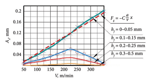
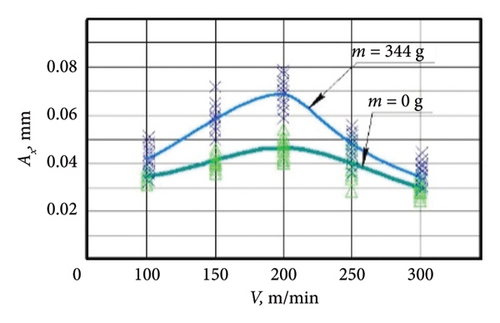
The red dashed line (Figure 10) shows the results obtained by Altintas et al. [24] for the case of negative damping caused by friction on the flank surface of the cutter with force Fg. Figure 11 shows the results of the study of the effect of additional mass on the vibration amplitude for a cutter-oscillator with area of wear of the CE.
6. Discussion
The cutter-oscillator was displaced under the action of the static component of the cutting force by the value xst = Bx in the SEP relative to which it performed oscillatory motion with amplitude Ax. 4 types of forces simultaneously affected the cutter-oscillator: cutting force, elastic reaction force, inertia force, and damping force. Physically, all these forces have different nature of origin and directions of action. Therefore, when cutting under regenerative SO conditions, there is a case of action of forces of mixed nature (Figure 12). It is known that if forces of mixed character can develop in mechanical systems, they are not decomposable into the sum of these forces. In particular, this applies to cutter-oscillating systems [25].
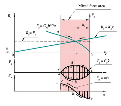
Since the cutter-oscillator has mass, on the wave of oscillatory motion (Figure 13), starting from the SEP position, the inertia force Fin increases, reaching its maximum value at points a, c, and e, where the acceleration has maximum values. However, the CE oscillation occurs in the medium of the sheared material, so naturally there is resistance to oscillatory motion, the value of which depends on the speed of oscillatory motion. With increasing speed, the resistance increases. Therefore, in points b and d, the speed of the maximum resistance (damping) force Fg will be maximum. And the direction of action of the force Fg will be opposite to the direction of motion of the cutter-oscillator.
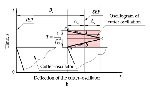
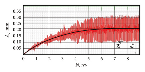
In this case, measuring the values of simultaneously acting forces is practically impossible. But, it is enough to simply measure and memorize graphically the law of motion of the cutter-oscillator from the simultaneous action of all these types of forces as an oscillogram of the deflection of CE (Figure 13). The deflection of the cutter-oscillator is completely determined by the oscillogram of its oscillations, which consists of two parts: a constant part, which is determined by the deviation of Bx from the IEP, and a variable part, which is determined by oscillations with amplitude relative to the SEP. The primary source of oscillation is the oscillation of the shear force due to the oscillation of the length of the conditional shear plane, when cutting along the “vibration trace” located on the free surface of the cut layer (Figure 4(b)). But, since the force Fs is related to the friction force Ffr by the condition of preservation of the chip equilibrium, naturally the oscillation of the force Fs will cause the oscillation of the force Ffr. If the rake angle CE is 0°, then the friction force Ffr is equal to the cutting force in the direction of the x-axis Fx, while Ffr acts on the chip, and Fx acts on the cutter. Therefore, the oscillation of force Ftr will be equal to the oscillation of force Fx. But the force Fx is balanced by the elastic reaction force Rx. In this case, the oscillations along the force chain are transmitted from the oscillations of force Fs to the oscillations of forces Fx and Rx. And the force Fx acts in the direction of pushing the cutter out of the cutting zone, and the reaction force Rx acts in the direction of returning the cutter to the cutting zone.
- 1.
Changing the mass of the cutter-oscillator has practically no effect on the static deflection Bx, which depends mainly on the rigidity of the cutter-oscillator.
- 2.
The vibration characteristics of the cutter-oscillator deflection in the form of amplitude Ax and frequency SO depend significantly on the mass. The amplitude increases and the frequency decreases because mass is a characteristic of inertia.
The obtained results are in full agreement with the theory of mechanical vibrations [11, 26]. They allow us to assert the possibility of effective application of the proposed methodology to study the physical basis of cutting dynamics under conditions of loading by forces of mixed character.
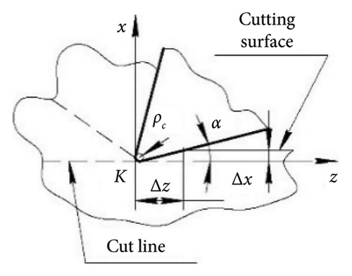
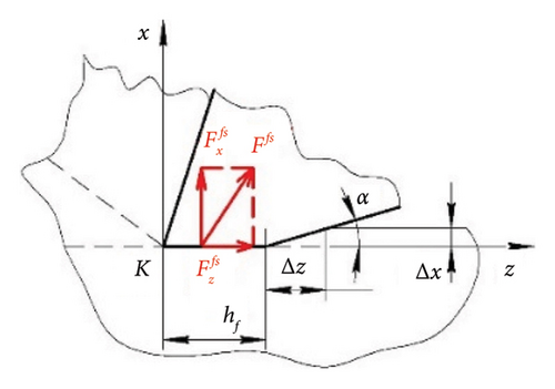
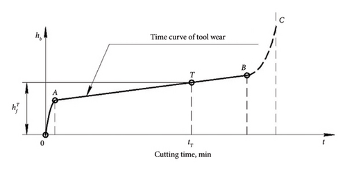
Figure 14 shows the conditions of contact of the flank surface of the oscillator cutter with the cutting surface when cutting without vibration. At the beginning of cutting (Figure 14(a)), the geometry of the flank surface is estimated by the clearance angle α and the cutting-edge radius ρc. As a result of the elastic recovery, the cutting surface is above the shear line by the value Δх, so the flank surface is in contact with the cutting surface for a length of Δz. However, due to the very high pressure in the CE area (point K), a flank wear land hf appears on the flank surface within a short time (Figure 14(b)) [27]. The flank wear land of the cutter is affected by the normal force and the friction force from the cutting surface, which are added to the forces acting from the side of the chips on the rake surface. The change in the size of the flank wear land is shown as a wear curve (Figure 14(c)) [28].
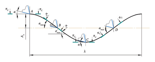
The effect of the friction force on the flank surface in regenerative SO has been studied quite well [29]. The cutting surface formed by the cutter during regenerative SO is wavy, which is usually depicted as a sinusoid. Figure 15 shows one wave of length λ, at different points of which the conditions of contact of the flank surface of the cutter with the cutting surface are shown. At each point A, B, C and D, the cutting plane (πC), tangent to the cutting surface, is shown. The actual clearance angle α lies between the flank surface of the cutter and the cutting plane (πC). At points A and C, the clearance angle α is equal to the nominal value. But at point B, the value of the clearance angle becomes minimal αmin or even negative, which sharply increases friction and makes it impossible for the flank surface to penetrate the cutting surface. At point D, the clearance angle has a maximum value αmax and the flank surface of the cutter does not contact the cutting surface. Thus, at point B, the cutting plane (πC) has the maximum angle of inclination σmax. With decreasing wavelength λ, the angle of inclination σmax should increase and, naturally, the clearance angle α will decrease, increasing the damping capacity of the flank surface.
The obtained experimental results fully confirm the existing provisions of cutting dynamics [29, 30].
According to this equation, with increasing cutting speed, the damping force decreases proportionally, and the oscillation amplitude increases.
The results of the experimental verification of this statement (Figure 10) showed that the condition equation (11) is satisfied only if there is no flank wear land hf on the flank surface of the cutter. But such a condition is maintained for a short time during the running-in period of the cutter—section of AO (Figure 14(c)). With an increase in the size of the area on the flank wear land hf > 0.05 mm, the vibration excitation intensity sharply decreases and has a different pattern. This pattern has a certain cutting speed v = 225 m/min at which maximum vibrations are observed. Above and below this cutting speed, the regenerative SO decreases and thereby highlights the speed range in which the regenerative SOs are excited.
The size of the wear land on the flank surface of the cutter has a greater effect on the damping of regenerative SO compared to the effect of friction on the flank surface of the cutter caused by a decrease in the actual clearance angle during cutting along “wave trace.” This is due to the fact that with an increase in the wear land on the flank surface of the cutter, the forces of resistance to the penetration CE into the cut allowance sharply increase.
7. Conclusions
Analysis of the system of forces arising during cutting showed that there are two groups of forces. The first group includes forces that arise directly during cutting. Chip formation and friction of the cutter against the chip and the cutting surface occur. The second group includes forces that are caused by the movement of a part or tool that has mass.
Each group of forces is determined by certain equilibrium conditions. The first group of forces is determined from the condition of equilibrium of the chip between the conditional plane of shear and the line of contact of the chip with the cutter. The second group of forces is determined from the conditions of equilibrium between the cutting force and the forces of elasticity, inertia, and damping of the cutter-oscillator. There is a direct and inverse relationship between these two groups of forces.
When cutting under regenerative SO conditions, mixed forces act on the cutter-oscillator, the contribution of which to the deflection of the CE cannot be estimated as the sum of these forces. Therefore, in this case, the oscillogram of the cutting tool deflections, as the law of its movement from the action of all types of forces, is an objective, well-reproducible criterion for assessing both static and dynamic conditions of the cutting process.
Conflicts of Interest
The authors declare no conflicts of interest.
Author Contributions
All authors have read and agreed to the published version of the manuscript.
Funding
No funding was received for this research.
Open Research
Data Availability Statement
The data that support the findings of this study are available from the corresponding author upon reasonable request.


