Volume 2025, Issue 1 1078161
Research Article
Open Access

Trigonometric Higher-Order Shear Deformation Theory on Exact Solution for Lateral and Longitudinal Dynamic Response of Magneto-Electric Carbon Nanotube-Reinforced Composite Beams Under Two Moving Loads Resting on Winkler–Pasternak Foundation

Mohammadreza Eghbali

Mohammadreza Eghbali

Department of Mechanical Engineering , University of Zanjan , Zanjan , Iran , znu.ac.ir

Search for more papers by this author
Seyed Amirhosein Hosseini

Corresponding Author

Seyed Amirhosein Hosseini

Department of Industrial , Mechanical and Aerospace Engineering , Buein Zahra Technical University , Qazvin , Iran , bzte.ac.ir

Search for more papers by this author
First published: 15 January 2025
Academic Editor: Vasudevan Rajamohan

Abstract

This paper aims to analyze the transverse and axial dynamic response of magneto-electric carbon nanotube-reinforced composite (CNTRC) beams under two moving constant loads resting on an elastic foundation. The governing equations of the magneto-electric CNTRC beam are obtained based on Mantari’s shear deformation beam theory, Hamilton’s principle, and Laplace transforms to solve the derived differential equations. The beams, which include a Winkler spring and shear layer, are considered as resting on the elastic foundation. The boundary conditions for this work are simply supported. This marks the inaugural instance in which a precise analytical approach rooted in mathematical principles has been employed to examine these constructions. The drawback inherent in this technique lies in its reliance on a simply supported boundary condition, stemming from the challenge associated with performing Laplace inversion on the Coupled equations. A comparison with previous studies has been conducted, which is a valuable contribution. Several examples were used to analyze the magnetic, voltage, and spring constant factors, the volume fraction of carbon nanotubes (CNTs), the velocity of a moving constant load, and their influence on the transverse and axial dynamic responses and maximum deflections.

1. Introduction

Carbon nanotubes (CNTs) are used to make nanoelectronic devices, lithium-ion batteries, membranes, electrochemical energy storage systems, chemical and biochemical sensors, and optoelectronic devices. These pipes are widely used in mechanical, electrical, and catalytic fields due to their high specific surface area. By adding to polymers, nanotubes create composites with suitable properties that perform better in conductivity than carbon black composites.

CNTs have found wide applications in modern medicine and are widely used in the field of medicine and biosensors. One of the first fields to study the use of carbon nanotubes in related drug delivery was cancer treatment [1].

Beams reinforced with CNTs have various applications in the electromagnetic environment. Some of the main applications include [2]:

Antennas: Carbon nanotube-reinforced beams can be used to create highly efficient and lightweight antennas for various applications such as satellite communication and radar systems.

Electromagnetic shielding: Carbon nanotube-reinforced beams can be used to create electromagnetic shields to protect electronic devices from electromagnetic interference.

Microwave devices: Carbon nanotube-reinforced beams can be used to create microwave devices such as filters, amplifiers, and switches.

Sensors: Carbon nanotube-reinforced beams can be used to create highly sensitive sensors for detecting electromagnetic fields [3].

Alibar et al. conducted a review of work done in the field of nanocomposites reinforced with CNTs and their effect on vibrations, specifically the effect of porosity [4]. Anh et al. studied the dynamic response and nonlinear vibrations of solar panels under temperature effects [5].

Babaei investigated the frequency response of CNTs under a thermal environment [6]. Bai et al. studied the vibrations of nanobeams under thermal and magnetic environments using strain gradient theory [7]. Deb Singha, Bandyopadhyay, and Karmakar studied the dynamic behavior of sandwich beams reinforced with CNTs under low-velocity impact [8].

Eghbali, Hosseini, and Rahmani studied the free vibrations of functionally graded nanobeams using strain gradient theory [9]. Esmaeili, Arvin, and Lacarbonara studied the nonlinear dynamic response of a multilayer piezoelectric nanocomposite microbeam with tip mass [10]. Garg et al. conducted a review of available theories and methodologies for the analysis of nanoisotropic, nanofunctionally graded, and carbon nanotube-reinforced nanocomposite structures [11].

In their research, Hosseini and Arvin [12] studied the vibrations of a functionally graded sandwich microbeam, while Li et al. [13] investigated the low-velocity impact response of sandwich plates with GRC face sheets and FG (functionally graded) auxetic 3D lattice cores. Mao, Guo, and Zhang [14] studied the vibrations and frequency analysis of graphene-amplified functional beams under a piezoelectric medium.

In their book, Nayal and Sharma [15] examined the piezoelectric effects. Penna, Lovisi, and Feo [16] studied the dynamic response of multilayered polymer FG carbon nanotube-reinforced composite (FG-CNTRC) nanobeams in the hygrothermal environment. Rajabi and Mohammadimehr [17] studied the forced vibration analysis of a micro sandwich plate with isotropic/orthotropic cores and polymeric nanocomposite face sheets. Swetha et al. [18] analyzed the vibrations of carbon nanotube-reinforced sandwich beams under a thermal environment. Van Vinh [19] studied the bending of graphene oxide-reinforced beams using a new first-order theory. Wei and Mohammadi [20] studied the hygrothermo-mechanical bending and vibration analysis of the CNTRC doubly curved nanoshells with thickness stretching. Yang, Sun, and Fu [21] studied a carbon nanotube-reinforced cylinder under a piezoelectric environment.

So far, in the study of the forced vibrations of these types of structures, no exact solution method has been provided, and the investigated methods are all numerical.

The objective of this study is to analyze the axial and transverse dynamic response of magneto-electric CNTRC beams under two moving constant loads. The governing equations of the CNTRC beam are obtained based on Mantari’s shear deformation beam theory and are solved using the Laplace transform. A detailed solution is presented for both transverse and axial responses. Valuable results have been obtained through parametric study, which sheds light on the effect of magnetic and voltage factors, spring constant, volume fraction of CNTs, and load velocity on the dynamic response of the magneto-electric CNTRC beams in axial and transverse modes.

The results of this study are validated by comparing them with available results in the literature, and good agreement is achieved. The insights provided in this study can be useful in the design of advanced structural materials for various engineering applications.

2. Formulation of the Problem

2.1. CNTRC Beams

This statement describes the geometry and loading conditions of a magneto-electric CNT beam system being analyzed. The beam is composed of three layers, with a magnetic layer of thickness hp sandwiched between two face layers of thickness h. The overall length of the beam is L. The beam is supported by an elastic foundation, and two fixed moving forces are applied to the beam.
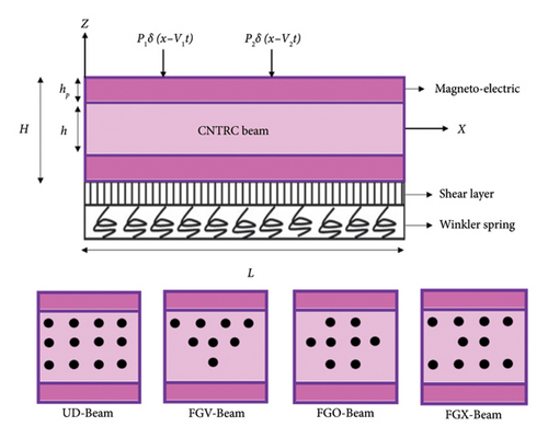
The expressions of the effective Young’s modulus and shear modulus of CNTRC beams are as follows [22]. Figure 1 shows the geometry of CNTRC magneto-electric beam and different reinforcement patterns.
E 11 = η 1 V C N E 11 C N + V k E k , η 2 E 22 = V C N E 22 C N + V k E k , η 3 G 12 = V C N G 12 C N + V k G k , ()
where G 12 C N , E 22 C N , and E 11 C N are defined as the shear modulus and Young’s modulus, respectively, and Ek, Gk as the properties of the polymer matrix. Also, VCN and Vk are the volume fraction, respectively, with the relation of VCN + Vk = 1. By using the same rule, Poisson’s ratio (υ) and mass density (ρ) of the CNTRC beams [23].
υ h = V C N υ C N + V k υ k , ()
ρ h = V C N ρ C N + V k ρ k , ()
where υCN, υk, ρCN, ρk, and αk are the Poisson’s ratios, densities, and thermal expansion coefficients, respectively [3].
UD Beam : V C N = V C N , V Beam : V C N = 1 + 2 z h V C N , O Beam : V C N = 2 1 2 z h V C N , X Beam : V C N = 2 2 z h V C N . ()
where V C N is the given volume fraction of CNTs [24].
V C N = S C N S C N + ρ C N / ρ k ρ C N / ρ k S C N , ()
where SCN is the mass fraction of CNT. From equation (5), the O-, X-, and V-Beams are examples of FG beams, where the material properties vary continuously through their thickness. In addition, the V-Beam has a uniformly distributed reinforcement of CNTs which can enhance its mechanical properties such as stiffness, strength, and damping. In this work, the CNT efficiency parameters (ηi) associated with the given volume fraction ( V C N ) are: η1 = 1.2833 and η2 = η3 = 1.0556 for V C N = 0.12; η1 = 1.3414; and η2 = η3 = 1.7101 for V C N = 0.17; η1 = 1.3238; and η2 = η3 = 1.7380 for V C N = 0.28 [22].
Details are in the caption following the image
Geometry of CNTRC magneto-electric beam and different reinforcement patterns.

2.2. Equations of Motion

In the shear deformation beam theory the displacement field can be expressed as follows [25]:
u x , z , t = u 0 z w 0 x , t x + Ψ z f 0 x , t , ()
w x , z , t = w 0 x , t , ()
where u0 and w0 are the axial and transverse displacement, respectively and Ψ(z) is shape function. f0 and Ψ(z), defined as the transverse shear strain [26]:
f 0 x , t = w 0 x , t x ϕ 0 x , t , Ψ z = Tan m z , m = 0.03 , ()
where ϕ0 is the total bending rotation, and t is time. The expression of normal and shear strain components in equation (7) follows [27].
ε x x = u 0 x z 2 w 0 x 2 + Ψ z 2 w 0 x 2 ϕ 0 x , ()
γ x z = Ψ z z w 0 x ϕ 0 . ()
The normal, shear, and magneto-electric stress, respectively σxx, σxz, and σ x x M including magnetic effect is given by the linear elastic constitutive law as [23]
σ x x = E 11 z , t ε x x , ()
σ x x M = C 11 ε x x , ()
σ x z = E 11 z 1 υ 2 z γ x z , Q 55 z = G 12 z , σ x z M = C 11 1 υ p 2 z γ x z , Q 55 m z = G 12 m z . ()

C11 denoting the reduced elastic.

2.3. Hamilton Principle

t 1 t 2 δ V δ K + δ U d t = 0 , δ U = δ U 1 + δ U 2 , ()
where δV external forces do the virtual work, δK is the virtual kinetic energy, and δU is the virtual variation of the total strain energy.
Strain energy δU = δU1 + δU2 is composed of the virtual strain energy of the beam δU1 and the virtual potential energy of the elastic foundation δU2. The virtual strain energy of the beam:
δ U 1 = A H / 2 H / 2 σ x x δ ε x x + σ x z δ γ x z d x d y d z = A N x d δ u 0 d x M x d 2 δ w 0 d x 2 + P x d 2 δ w 0 d x 2 d δ ϕ 0 d x + Q x d δ w 0 d x δ ϕ 0 d A , ()
δ U 2 = 0 L k w w 0 δ w 0 k s d w 0 d x d δ w 0 d x d x , k w = β w A 110 L 2 , k s = β s A 110 . ()

In equation (16), kw and ks are the Winkler and shearing layer spring constants. βw and βs are the corresponding spring constant factors.

The virtual work done (δV) can be expressed as [28]
δ V = 0 L f δ w 0 + N x 0 d w 0 d x d δ w 0 d x d x , N x 0 = N M + N P , f = P 1 δ x V 1 t + P 2 δ x V 2 t , ()
where the transverse force (f), V1 and V2 speed of moving loads, δ(.) is Dirac delta function and axially compressive force (Nx0).
δ K = 0 L ρ z u ˙ δ u ˙ + w ˙ δ w ˙ d A d x = 0 L I 0 u ˙ 0 δ u ˙ 0 + w ˙ 0 δ w ˙ 0 I 1 d w ˙ 0 d x δ u ˙ 0 + u ˙ 0 d δ w ˙ 0 d x + I 2 d w ˙ 0 d x d δ w ˙ 0 d x + I 3 d w ˙ 0 d x δ u ˙ 0 ϕ ˙ 0 δ u ˙ 0 + u ˙ 0 d δ w ˙ 0 d x u ˙ 0 δ ϕ ˙ 0 + I 4 ϕ ˙ 0 d δ w ˙ 0 d x 2 d w ˙ 0 d x d δ w ˙ 0 d x + d w ˙ 0 d x δ ϕ ˙ 0 + I 5 d w ˙ 0 d x d δ w ˙ 0 d x ϕ ˙ 0 d δ w ˙ 0 d x d w ˙ 0 d x δ ϕ ˙ 0 + ϕ ˙ 0 δ ϕ ˙ 0 d x . ()
The stress results are extracted as
N x = h / 2 h / 2 σ x x d z + h / 2 h / 2 + h P σ x x M d z + h / 2 + h P h / 2 σ x x M d z , ()
M x = h / 2 h / 2 z σ x x d z + h / 2 h / 2 + h P z σ x x M d z + h / 2 + h P h / 2 z σ x x M d z , ()
P x = h / 2 h / 2 Ψ z σ x x d z + h / 2 h / 2 + h P Ψ z σ x x M d z + h / 2 + h P h / 2 Ψ z σ x x M d z , ()
Q x = h / 2 h / 2 d Ψ z d z σ x z d z + h / 2 h / 2 + h P d Ψ z d z σ x z M d z + h / 2 + h P h / 2 d Ψ z d z σ x z M d z , ()
where Nx, Mx, Px, and Qx are the stress resultants in terms of the normal force, bending moment, higher-order generalized force, and shear force, respectively. Where the superscripts “M” and “P” in equation (17) represent the magnetic and electric loads, respectively, and NM, as well as NP, are defined as
N P = H / 2 H / 2 E d 31 E z d z , N M = E M H x 2 2 w x 2 , ()
where the superposed dot on a variable indicates time derivative and Ii (i = 0, 1, 2, …, 5) are the mass moments of inertia defined as [25]
I 0 , I 1 , I 2 = h / 2 h / 2 ρ h 1 , z , z 2 d z + h / 2 h / 2 + h P ρ P 1 , z , z 2 d z + h / 2 + h P h / 2 ρ P 1 , z , z 2 d z , ()
I 3 , I 4 = h / 2 h / 2 ρ h Ψ z 1 , z d z + h / 2 h / 2 + h P ρ P Ψ z 1 , z d z + h / 2 + h P h / 2 ρ P Ψ z 1 , z d z , ()
I 5 = h / 2 h / 2 ρ h Ψ 2 z d z + h / 2 h / 2 + h P ρ P Ψ 2 z d z + h / 2 + h P h / 2 ρ P Ψ 2 z d z . ()
Using equation (14) and, equations (15)–(17) solving the relationship and factorization, the equilibrium equation results in the following effect [25]:
δ u 0 : d N x d x = I 0 u ¨ 0 I 1 d w ¨ 0 d x + I 3 d w ¨ 0 d x ϕ ¨ 0 , δ w 0 : d 2 P x d x 2 d 2 M x d x 2 + d Q x d x + k w w 0 k s d 2 w 0 d x 2 f + N x 0 d 2 w 0 d x 2 = I 0 w ¨ 0 I 1 d u ¨ 0 d x + I 2 d 2 w ¨ 0 d x 2 + I 3 d u ¨ 0 d x + I 4 d ϕ ¨ 0 d x 2 d 2 w ¨ 0 d x 2 + I 5 d 2 w ¨ 0 d x 2 d ϕ ¨ 0 d x , δ ϕ 0 : d P x d x Q x = I 3 u ¨ 0 + I 4 d w ¨ 0 d x I 5 d w ¨ 0 d x ϕ ¨ 0 . ()
From the above relations, all stress resultants can be written in the form of material stiffness components and displacements as follows [25]:
N x = A 11 d u 0 d x B 11 d 2 w 0 d x 2 + C 110 d 2 w 0 d x 2 d ϕ 0 d x , ()
M x = B 11 d u 0 d x D 11 d 2 w 0 d x 2 + E 110 d 2 w 0 d x 2 d ϕ 0 d x , ()
P x = C 110 d u 0 d x E 110 d 2 w 0 d x 2 + H 11 d 2 w 0 d x 2 d ϕ 0 d x , ()
Q x = A 55 d w 0 d x ϕ 0 , ()
where [28]
A 11 , B 11 , D 11 = h / 2 h / 2 E 11 1 , z , z 2 d z + h / 2 h / 2 + h P C 11 1 , z , z 2 d z + h / 2 + h P h / 2 C 11 1 , z , z 2 d z , ()
C 110 , E 110 = h / 2 h / 2 E 11 Ψ z 1 , z d z + h / 2 h / 2 + h P C 11 Ψ z 1 , z d z + h / 2 + h P h / 2 C 11 Ψ z 1 , z d z , ()
H 11 = h / 2 h / 2 E 11 Ψ 2 z d z + h / 2 h / 2 + h P C 11 Ψ 2 z d z + h / 2 + h P h / 2 C 11 Ψ 2 z d z , ()
A 55 = h / 2 h / 2 Q 55 d Ψ z d z 2 d z + h / 2 h / 2 + h P Q 55 m d Ψ z d z 2 d z + h / 2 + h P h / 2 Q 55 m d Ψ z d z 2 d z . ()
The stress resultants of equations (28)–(31) are substituted into equation (27) to obtain the equations of motion or the governing equations in the form of displacements as follows [28]:
A 11 d 2 u 0 d x 2 B 11 d 3 w 0 d x 3 + C 110 d 3 w 0 d x 3 d 2 ϕ 0 d x 2 = I 0 u ¨ 0 I 1 d w ¨ 0 d x + I 3 d w ¨ 0 d x ϕ ¨ 0 , ()
C 110 d 3 u 0 d x 3 E 110 d 4 w 0 d x 4 + H 11 d 4 w 0 d x 4 d 3 ϕ 0 d x 3 B 11 d 3 u 0 d x 3 + D 11 d 4 w 0 d x 4 E 110 d 4 w 0 d x 4 d 3 ϕ 0 d x 3 + A 55 d 2 w 0 d x 2 d ϕ 0 d x + k w w 0 k s d 2 w 0 d x 2 f + N x 0 d 2 w 0 d x 2 = I 0 w ¨ 0 I 1 d u ¨ 0 d x + I 2 d 2 w ¨ 0 d x 2 + I 3 d u ¨ 0 d x I 4 d ϕ ¨ 0 d x 2 d 2 w ¨ 0 d x 2 + I 5 d 2 w ¨ 0 d x 2 d ϕ ¨ 0 d x , ()
C 110 d 2 u 0 d x 2 + E 110 d 3 w 0 d x 3 H 11 d 3 w 0 d x 3 d 2 ϕ 0 d x 2 A 55 d w 0 d x ϕ 0 = I 3 u ¨ 0 + I 4 d w ¨ 0 d x I 5 d w ¨ 0 d x ϕ ¨ 0 . ()

2.4. Exact Solution

To start the exact solution, the following assumptions are first considered [2, 25].
u 0 x , t = n = 1 U n t cos n π x L , ()
ϕ 0 x , t = n = 1 Φ n t cos n π x L , ()
w 0 x , t = n = 1 W n t sin n π x L , ()
Un(t), Wn(t), and Φn(t) are the unknown Fourier coefficients to be determined for each n value. By using the general property of the Dirac Delta function as follows [25]:
δ x V 1 t = 2 n = 1 sin n π x L sin n π V 1 t L , δ x V 2 t = 2 n = 1 sin n π x L sin n π V 2 t L . ()
Assuming:
α = n π L . ()
The exact solution presented in this work is limited by the assumption of simple boundary conditions. The beams are assumed to be simply supported at their ends without any other complex boundary conditions. In real-world applications, beams may have more complex boundary conditions, such as clamped, free, or mixed boundary conditions. In such cases, the exact solution may not be applicable, and other methods such as numerical or approximate analytical methods may be more suitable. Therefore, it is important to carefully consider the boundary conditions present in the problem and choose an appropriate solution method accordingly to avoid any inaccuracies in the results:
W n 0 = W ˙ n 0 = U n 0 = U ˙ n 0 = Φ n 0 = Φ ˙ n 0 = 0 . ()
To solve the system of the differential equations (38)–(40) in the time domain, Laplace transform is utilized. By recalling this transformation as follows [28]:
L W ¨ n t = s 2 W n s s W n 0 W ˙ n 0 , W n s = L W n t , L U ¨ n t = s 2 U n s s U n 0 U ˙ n 0 , U n s = L U n t , L Φ ¨ n t = s 2 Φ n s s Φ n 0 Φ ˙ n 0 , Φ n s = L Φ n t , ()
where applied Laplace Transform in equations (38)–(40), the system of equation is obtained as follows [28]:
K 11 K 12 K 13 K 21 K 22 K 23 K 31 K 32 K 33 U n s W n s Φ n s = 0 F 0 , ()
where
K 11 = A 11 α 2 + I 0 s 2 , K 12 = K 21 = B 11 α 3 C 110 α 3 + I 1 α s 2 I 3 α s 2 , K 13 = K 31 = C 110 α 2 + I 3 s 2 , K 22 = 22 E 110 α 4 + H 11 α 4 + D 11 α 4 + A 55 α 2 + k w + k s α 2 N x 0 α 2 + I 0 s 2 + I 2 α 2 s 2 I 4 α 2 s 2 + I 5 α 2 s 2 , K 23 = K 32 = H 11 α 3 + E 110 α 3 A 55 α + I 4 α s 2 I 5 α s 2 , K 33 = H 11 α 2 + A 55 + I 5 s 2 , F = 2 P 1 α V 1 s 2 + α V 1 2 + 2 P 2 α V 2 s 2 + α V 2 2 . ()
By solving equation (46), Un(s), Wn(s), and Φn(s) are obtained as
U n s W n s Φ n s = 1 det K F K 13 K 23 + K 12 K 33 F K 13 2 K 11 K 33 F K 12 K 13 K 11 K 23 , det K = K 13 2 K 22 2 K 12 K 13 K 23 + K 11 K 23 2 + K 12 2 K 33 K 11 K 22 K 33 . ()
By applying an inverse Laplace transform to equation (48), the transverse and axial dynamic response of the thermoelectric CNTRC beam is obtained [25, 28]:
U n x , t = 1 y 2 y 1 sin d 18 t d 18 + 1 y 4 y 3 sin d 20 t d 20 + g 6 f 0 + x 1 f 2 + f 4 x 1 x 2 x 2 x 3 x 3 sinh t x 1 + g 6 x 1 f 0 + x 2 f 2 + f 4 x 2 x 1 x 3 x 3 sinh t x 2 + x 2 x 1 + x 2 f 0 + x 3 f 2 + f 4 x 3 sinh t x 3 x 1 x 2 x 3 g 2 g 4 32 g 0 g 6 + g 6 2 x 1 x 2 2 + x 1 2 x 3 + x 2 x 3 2 , ()
W n x , t = 1 y 2 y 5 sin d 18 t d 18 + 1 y 4 y 6 sin d 20 t d 20 + g 6 J 0 + x 1 J 2 + J 4 x 1 x 2 x 2 x 3 x 3 sinh t x 1 + g 6 x 1 J 0 + x 2 J 2 + J 4 x 2 x 1 x 3 x 3 sinh t x 2 + x 2 x 1 + x 2 J 0 + x 3 J 2 + J 4 x 3 sinh t x 3 x 1 x 2 x 3 g 2 g 4 32 g 0 g 6 + g 6 2 x 1 x 2 2 + x 1 2 x 3 + x 2 x 3 2 , ()
Φ n x , t = 1 y 2 y 7 sin d 18 t d 18 + 1 y 4 y 8 sin d 20 t d 20 + g 6 R 0 + x 1 R 2 + R 4 x 1 x 2 x 2 x 3 x 3 sinh t x 1 + g 6 x 1 R 0 + x 2 R 2 + R 4 x 2 x 1 x 3 x 3 sinh t x 2 + x 2 x 1 + x 2 R 0 + x 3 R 2 + R 4 x 3 sinh t x 3 x 1 x 2 x 3 g 2 g 4 32 g 0 g 6 + g 6 2 x 1 x 2 2 + x 1 2 x 3 + x 2 x 3 2 . ()

To see the constant coefficients used in equations (48)–(50), refer to the Appendix section A.

3. Analytical Results and Discussions

It should be noted that this study is based on analytical methods using higher order shear deformation theory and Laplace transform to solve the governing equations of the CNTRC beams. The results showed that the parameters mentioned above have a significant effect on the forced vibrations and displacement of the CNTRC beams. The aspect ratio of the transverse and axial displacement of the CNTRC beams was increased by increasing the thickness, magnetic changes, voltage, and load speed. On the other hand, increasing the spring constant and magnetic volume fraction resulted in a decrease in transverse and axial displacement. Additionally, it was found that the O, V, UD, and X beams had the highest transverse and axial displacement, respectively, and the O-Beam had the weakest resistance to flexural loads.
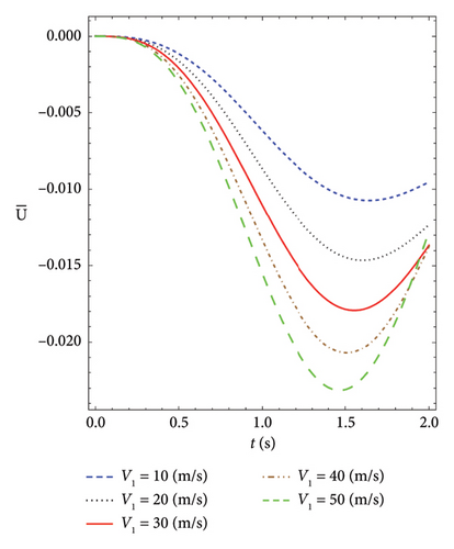
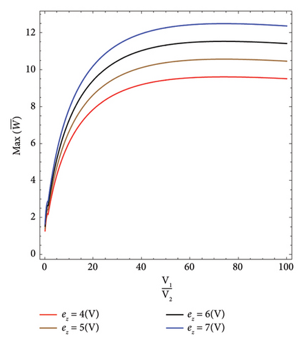
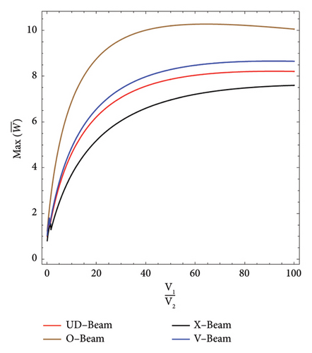
Moreover, Figures 2, 3, 4, 5, 6, 7, 8, 9, 10, 11, 12, 13, and 14 illustrate the variations of maximum dimensionless transverse and axial displacements of the V-Beam and CNTRC beams on elastic and Pasternak foundations under different parameters, such as spring constant, magnetic, voltage, and load velocity. Finally, dimensionless natural frequencies were calculated using equation (52).
ω ¯ = λ L 2 h ρ k E k . ()
Details are in the caption following the image
Variation of axial dynamic deflection for the different velocity of moving load (P1 = P2). V 2 = 301000.02300.1210000100000.1 , L / h = , β s = , E M = , V C N = , P 1 = , P 2 = , β w =.
Details are in the caption following the image
Variation of axial dynamic deflection for the different velocity of moving load (P1 = −P2). V 2 = 301000.02300.1210000100000.1 , L / h = , β s = , E M = , V C N = , P 1 = , P 2 = , β w =.
Details are in the caption following the image
Variation of dynamic deflection for different spring constant of moving load. V 1 = 10201000.02300.12 , V 2 = , L / h = , β s = , E M = , V C N =.
Details are in the caption following the image
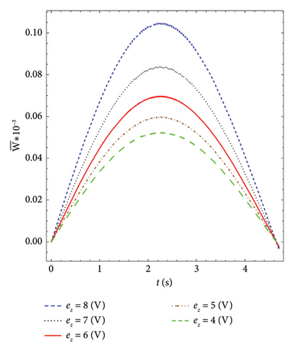
Variation of dynamic deflection for different voltage of moving load. V 1 = 10201000.10.0200.12 , V 2 = , L / h = , β w = , β s = , E M = , V C N =.
Details are in the caption following the image
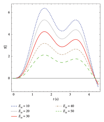
Variation of dynamic deflection for different magnetic of moving load. V 1 = 10201000.10.0200.12 , V 2 = , L / h = , β w = , β s = , e z = , V C N =.
Details are in the caption following the image
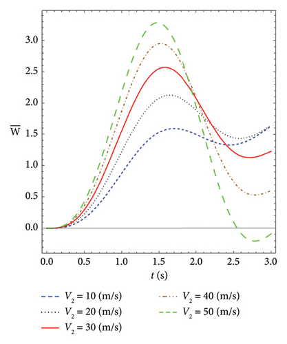
Variation of dynamic deflection for the different velocity of moving load (P1 = P2). V 2 = 301000.02300.1210000100000.1 , L / h = , β s = , E M = , V C N = , P 1 = , P 2 = , β w =.
Details are in the caption following the image
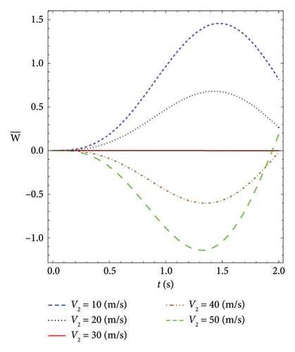
Variation of dynamic deflection for the different velocity of moving load (P1 = −P2). V 1 = 301000.02300.1210000100000.1 , L / h = , β s = , E M = , V C N = , P 1 = , P 2 = , β w =.
Details are in the caption following the image
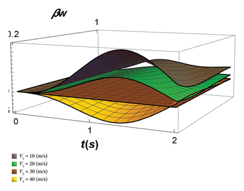
3D plot for dynamic deflection V-Beam on Pasternak foundation versus time and spring constant for the different velocity. V 2 = 301000.02300.121000010000 , L / h = , β s = , E M = , V C N = , P 1 = , P 2 = .
Details are in the caption following the image
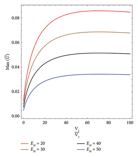
Maximum displacements of V-Beam on Pasternak foundation for different magnetic. V 1 = 10201000.0200.120.1 , V 2 = , L / h = , β s = , e z = , V C N = , β w =.
Details are in the caption following the image
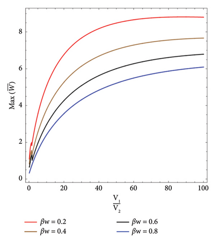
Maximum displacements of V-Beam on Pasternak foundation under moving load versus velocity ratio for different spring constant. V 1 = 10201000.0200.12 , V 2 = , L / h = , β s = , E M = , V C N =.
Details are in the caption following the image
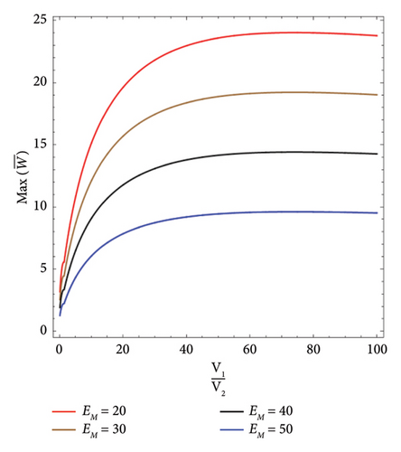
Maximum displacements of V-Beam on Pasternak foundation under moving load versus velocity ratio for different magnetic. V 1 = 10201000.0200.120.1 , V 2 = , L / h = , β s = , e z = , V C N = , β w =.
Details are in the caption following the image
Maximum displacements of V-Beam on Pasternak foundation under moving load versus velocity ratio for different voltage. V 1 = 10201000.0200.120.1 , V 2 = , L / h = , β s = , E M = , V C N = , β w =.
Details are in the caption following the image
Maximum displacements of CNTRC beams on Pasternak foundation under moving load versus velocity ratio. V 1 = 10201000.10.0200.1230 , V 2 = , L / h = , β w = , β s = , e z = , V C N = , E M =.

3.1. Validation

The results are compared with, given in Table 1. Also, the dimensions of the beam are: L/h = 100, L = 100, hp = 0.1.

Table 1. Comparisons of frequencies for CNTRC beams for HSDT L / h = 150.12 , V C N =.
UD-Beam V-Beam O-Beam X-Beam
ω ¯ 1 0.974908 0.745672 1.11562 0.844435
ω ¯ 1 (Wattanasakulpong and Ungbhakorn, 2013) 0.9745 0.7454 1.1151 0.8441
ω ¯ 2 2.88138 2.39797 3.10205 2.6492
ω ¯ 3 4.93056 4.29371 5.16984 4.68817
ω ¯ 4 7.01828 6.22862 7.2849 6.79126

Material properties are: υk = 0.3; ρk = 1190 kg/m3; and Ek = 2.5 GPa. Reinforcement materials are: υCN = 0.19; ρCN = 1400 kg/m3; E 11 C N = 600  GPa; E 22 C N = 10  GPa; and G 12 C N = 17.2  GPa [22], is also chosen Hx = 0.02, d31 = 0.254 m/v [25, 28].

As shown in Table 1, among different types of CNTRC beams, frequency O-Beam is the lowest, and X-Beam is the highest.

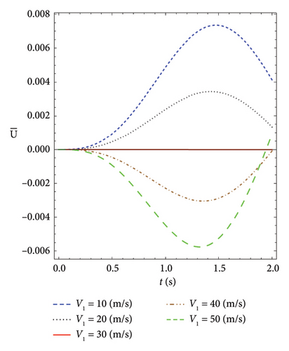
The properties of the materials in Figures 2 and 3 are the same, except that the applied forces are opposite each other. The following is a description of these items for Figures 2 and 3.

Figure 2 shows the plot of axial displacement versus time for the different velocities of moving load. As can be seen, both forces are positive (P1 = P2), and increasing the velocity increases the displacement.

However, in Figure 3, the first force is opposing, the second force (P1 = −P2). When the velocity of the first force is higher, the axial displacement acts based on the first force because it reaches the center of the beam sooner. When both speeds are equal, the force is zero, and the axial displacement is zero. Finally, when the velocity of the second force is greater than that of the first force, the axial displacement behaves according to the second force.

Figure 4 shows the transverse displacements of V-Beam on an elastic foundation for different spring constants versus time. As seen in the figure, the transverse displacement decreases as the spring constant increases.

Figure 5 shows the transverse displacements of V-Beam on an elastic foundation for different voltages versus time. As seen in the figure, the transverse displacement increases as the voltage increases.

Figure 6 shows the transverse displacements of V-Beam on an elastic foundation for different magnetics versus time. As seen in the figure, the transverse displacement decreases as the magnetic field intensity increases.

The properties of the materials in Figures 7 and 8 are the same, except that the applied forces are opposite each other. The following is a description of these items for Figures 7 and 8.

Figure 7 shows the plot of transverse displacement versus time for the different velocities of moving load. As can be seen, both forces are positive (P1 = P2), and increasing the velocity increases the transverse displacement.

However, in Figure 8, the first force is opposing, the second force (P1 = −P2). When the velocity of the second force is higher, the transverse displacement acts based on the second force because it reaches the center of the beam sooner. When both speeds are equal, the force is zero, and the transverse displacement is zero. Finally, when the velocity of the first force is greater than that of the second force, the transverse displacement behaves according to the first force.

The interpretation of Figure 8 also applies to Figure 9, except that the axial displacement decreases with increasing elastic constant.

In Figure 10, the maximum dimensionless axial displacements of the V-Beam on an elastic foundation under a moving load versus velocity ratio for different magnetic fields are shown. As the magnetic field increases, the maximum dimensionless axial displacements decrease.

In Figure 11, the maximum dimensionless transverse displacement of the V-Beam on an elastic foundation under a moving load is shown for different spring constants. It can be observed that as the spring constant increases, the maximum dimensionless transverse displacement decreases. Generally, a stiffer elastic foundation can limit the deflection and displacement of the beam, while a more flexible bed may allow for higher levels of displacement.

It is important to consider the interaction between the beam and the elastic foundation when analyzing and designing carbon nanotube-reinforced beams to ensure proper structural performance and desired displacement characteristics.

In Figure 12, the maximum dimensionless transverse displacement of the V-Beam on an elastic foundation under a moving load is shown for different magnetic strengths. It can be observed that as the magnetic strength increases, the maximum dimensionless transverse displacement decreases.

The effect of magnetism on the displacement of beams reinforced with CNTs depends on the specific conditions and properties of the beam and the magnetic field. In general, a magnetic field can induce Lorentz forces on the CNTs, which can affect the deformation and displacement of the beam.

If the magnetic field is strong enough, it can cause significant deflection and displacement of the beam. This effect can be utilized in various applications such as magnetic actuation or sensing. However, if the magnetic field is not properly controlled or accounted for, it can also lead to unwanted deformation or instability of the beam.

Therefore, when designing carbon nanotube-reinforced beams for applications involving magnetism, it is important to consider the interaction between the beam and the magnetic field and to properly account for any induced forces or effects on the structural behavior of the beam.

In Figure 13, the maximum dimensionless transverse displacement of the V-Beam on an elastic foundation under a moving load is shown for different velocities. It can be observed that as the velocity increases, the maximum dimensionless transverse displacement also increases.

In Figure 14, the maximum dimensionless transverse displacement of the CNTRC beams on an elastic foundation under a moving load is shown for different reinforcement patterns. It can be seen that beams O, V, UD, and X have the highest maximum transverse dynamic deflection, respectively.

As the aspect ratio of the beams increases, they become relatively slender in one dimension compared to the others. This makes them more susceptible to bending and flexural deformations, leading to increased transverse and axial displacements. Additionally, higher velocity and voltage can introduce more energy into the system, causing greater vibrations and displacements.

A higher spring constant indicates a stiffer structure, meaning it resists deformation more effectively. This stiffness restrains the transverse displacement and bending of the beams. On the other hand, magnetic forces can counteract the deformation tendencies by introducing repulsive or attractive forces that counterbalance the bending effect.

The observation that the O, V, UD, and X beams among the CNTRC beams display the highest transverse and axial displacements indicates that the O-beam possesses the least resistance against flexural loads. This outcome can be attributed to the specific geometrical and structural properties of the O-beam, which make it more susceptible to bending and deformation under the applied forces.

4. Conclusion

The present study aims to investigate the transverse and axial dynamic response of magneto-electric CNTRC beams subjected to two moving constant loads and placed on the Pasternak foundation. To obtain the governing equations of the beam, the higher-order shear deformation theory, Hamilton principle, and Laplace transform are used to solve the resulting differential equations.

Based on the analytical results, it was found that the thickness of the beam, magnetic changes, voltage, spring constant, and moving load speed have a significant effect on the forced vibrations and transverse and axial displacement of CNTRC beams.
  • Among the CNTRC beams, the O, V, UD, and X beams exhibit the highest transverse and axial displacement, respectively, indicating that the O-beam has the weakest resistance to flexural loads.
  • Transverse and axial displacements of the beams increased with their aspect ratios and voltage.

  • Spring constant, velocity, and magnetic results caused reduction in transverse displacement and bending.

  • Exact solution is suitable for simply supported boundary conditions but might not be effective for practical complex conditions.

  • Selecting an appropriate solution method based on boundary conditions is crucial.

Recommended future works include investigating the exact solution of sandwich beams under accelerated dynamic force. Also, find the exact solution method for other boundary conditions.

Conflicts of Interest

The authors declare no conflicts of interest.

Funding

The research did not receive funding from any sources.

Appendix A: Complete Definition of Formulation

In the following, the terms used in equations (48)–(50) are defined. These are included here to avoid lengthy equations and cluttered pages, as well as to reduce reader fatigue in this section.
u 1 = 1 , u 2 = 1 + I 3 2 , u 3 = 1 I 3 2 , Δ 0 = g 4 2 32927 g 6 g 2 , Δ 1 = g 4 3 g 6 g 4 g 2 + g 6 2 g 0 , C i = Δ 1 + Δ 1 2 4 Δ 0 3 2 3 , x 1 = 1 3 g 6 g 4 + u 1 C i + Δ 0 u 1 C i , x 2 = 1 3 g 6 g 4 + u 2 C i + Δ 0 u 2 C i , x 3 = 1 3 g 6 g 4 + u 3 C i + Δ 0 u 3 C i , ()
y 1 = d 6 d 12 d 17 + d 3 d 15 d 17 + d 7 d 12 d 17 d 18 + d 6 d 13 d 17 d 18 + d 6 d 14 d 17 d 18 d 4 d 15 d 17 d 18 d 5 d 15 d 17 d 18 d 3 d 16 d 17 d 18 d 7 d 13 d 17 d 18 2 d 7 d 14 d 17 d 18 2 + d 4 d 16 d 17 d 18 2 + d 5 d 16 d 17 d 18 2 , y 2 = d 6 2 d 8 22 d 3 d 6 d 12 + d 1 d 12 2 + d 3 2 d 15 d 1 d 8 d 15 d 2 d 6 2 d 18 d 6 d 7 d 8 d 18 d 6 2 d 9 d 18 d 6 2 d 10 d 18 d 6 2 d 11 d 18 + 2222222 d 4 d 6 d 12 d 18 + d 5 d 6 d 12 d 18 + d 3 d 7 d 12 d 18 d 2 d 12 2 d 18 + d 3 d 6 d 13 d 18 d 1 d 12 d 13 d 18 + d 3 d 6 d 14 d 18 d 1 d 12 d 14 d 18 + d 1 d 2 d 15 d 18 22 d 3 d 4 d 15 d 18 d 3 d 5 d 15 d 18 + d 2 d 8 d 15 d 18 + d 1 d 9 d 15 d 18 + d 1 d 10 d 15 d 18 + d 1 d 11 d 15 d 18 d 3 2 d 16 d 18 + d 1 d 8 d 16 d 18 + 222222 d 2 d 6 d 7 d 18 2 + d 7 2 d 8 d 18 2 + d 6 d 7 d 9 d 18 2 + d 6 d 7 d 10 d 18 2 + d 6 d 7 d 11 d 18 2 d 4 d 7 d 12 d 18 2 d 5 d 7 d 12 d 18 2 2222222 d 4 d 6 d 13 d 18 2 d 5 d 6 d 13 d 18 2 d 3 d 7 d 13 d 18 2 + d 2 d 12 d 13 d 18 2 + d 1 d 13 2 d 18 2 d 4 d 6 d 14 d 18 2 d 5 d 6 d 14 d 18 2 d 3 d 7 d 14 d 18 2 + 222 d 2 d 12 d 14 d 18 2 + d 1 d 13 d 14 d 18 2 + d 1 d 14 2 d 18 2 d 2 2 d 15 d 18 2 + d 4 2 d 15 d 18 2 + d 4 d 5 d 15 d 18 2 + d 5 2 d 15 d 18 2 d 2 d 9 d 15 d 18 2 d 2 d 10 d 15 d 18 2 d 2 d 11 d 15 d 18 2 d 1 d 2 d 16 d 18 2 + 22 d 3 d 4 d 16 d 18 2 + d 3 d 5 d 16 d 18 2 d 2 d 8 d 16 d 18 2 d 1 d 9 d 16 d 18 2 d 1 d 10 d 16 d 18 2 d 1 d 11 d 16 d 18 2 d 2 d 7 2 d 18 3 d 7 2 d 9 d 18 3 d 7 2 d 10 d 18 3 d 7 2 d 11 d 18 3 + 2222 d 4 d 7 d 13 d 18 3 + d 5 d 7 d 13 d 18 3 d 2 d 13 2 d 18 3 + d 4 d 7 d 14 d 18 3 + d 5 d 7 d 14 d 18 3 22 d 2 d 13 d 14 d 18 3 d 2 d 14 2 d 18 3 + d 2 2 d 16 d 18 3 d 4 2 d 16 d 18 3 d 4 d 5 d 16 d 18 3 d 5 2 d 16 d 18 3 + d 2 d 9 d 16 d 18 3 + d 2 d 10 d 16 d 18 3 + d 2 d 11 d 16 d 18 3 , y 3 = d 6 d 12 d 19 + d 3 d 15 d 19 + d 7 d 12 d 19 d 20 + d 6 d 13 d 19 d 20 + d 6 d 14 d 19 d 20 d 4 d 15 d 19 d 20 d 5 d 15 d 19 d 20 d 3 d 16 d 19 d 20 d 7 d 13 d 19 d 20 2 d 7 d 14 d 19 d 20 2 + d 4 d 16 d 19 d 20 2 + d 5 d 16 d 19 d 20 2 , y 4 = d 6 2 d 8 22 d 3 d 6 d 12 + d 1 d 12 2 + d 3 2 d 15 d 1 d 8 d 15 d 2 d 6 2 d 20 d 6 d 7 d 8 d 20 d 6 2 d 9 d 20 d 6 2 d 10 d 20 d 6 2 d 11 d 20 + 222222 d 4 d 6 d 12 d 20 + d 5 d 6 d 12 d 20 + d 3 d 7 d 12 d 20 d 2 d 12 2 d 20 + d 3 d 6 d 13 d 20 d 1 d 12 d 13 d 20 + d 3 d 6 d 14 d 20 222 d 1 d 12 d 14 d 20 + d 1 d 2 d 15 d 20 d 3 d 4 d 15 d 20 d 3 d 5 d 15 d 20 + d 2 d 8 d 15 d 20 + d 1 d 9 d 15 d 20 + d 1 d 10 d 15 d 20 + d 1 d 11 d 15 d 20 d 3 2 d 16 d 20 + d 1 d 8 d 16 d 20 + 22222 d 2 d 6 d 7 d 20 2 + d 7 2 d 8 d 20 2 + d 6 d 7 d 9 d 20 2 + d 6 d 7 d 10 d 20 2 + d 6 d 7 d 11 d 20 2 d 4 d 7 d 12 d 20 2 222222 d 5 d 7 d 12 d 20 2 d 4 d 6 d 13 d 20 2 d 5 d 6 d 13 d 20 2 d 3 d 7 d 13 d 20 2 + d 2 d 12 d 13 d 20 2 + d 1 d 13 2 d 20 2 d 4 d 6 d 14 d 20 2 22222 d 5 d 6 d 14 d 20 2 d 3 d 7 d 14 d 20 2 + d 2 d 12 d 14 d 20 2 + d 1 d 13 d 14 d 20 2 + d 1 d 14 2 d 20 2 d 2 2 d 15 d 20 2 + d 4 2 d 15 d 20 2 + d 4 d 5 d 15 d 20 2 + d 5 2 d 15 d 20 2 d 2 d 9 d 15 d 20 2 d 2 d 10 d 15 d 20 2 d 2 d 11 d 15 d 20 2 d 1 d 2 d 16 d 20 2 + 22 d 3 d 4 d 16 d 20 2 + d 3 d 5 d 16 d 20 2 d 2 d 8 d 16 d 20 2 d 1 d 9 d 16 d 20 2 d 1 d 10 d 16 d 20 2 d 1 d 11 d 16 d 20 2 d 2 d 7 2 d 20 3 d 7 2 d 9 d 20 3 d 7 2 d 10 d 20 3 d 7 2 d 11 d 20 3 + 22 d 4 d 7 d 13 d 20 3 + d 5 d 7 d 13 d 20 3 d 2 d 13 2 d 20 3 + 2222 d 4 d 7 d 14 d 20 3 + d 5 d 7 d 14 d 20 3 d 2 d 13 d 14 d 20 3 d 2 d 14 2 d 20 3 + d 2 2 d 16 d 20 3 d 4 2 d 16 d 20 3 d 4 d 5 d 16 d 20 3 d 5 2 d 16 d 20 3 + d 2 d 9 d 16 d 20 3 + d 2 d 10 d 16 d 20 3 + d 2 d 11 d 16 d 20 3 , ()
g 0 = d 6 2 d 8 2 d 3 d 6 d 12 + d 1 d 12 2 + d 3 2 d 15 d 1 d 8 d 15 , g 2 = d 2 d 6 2 + 222222 d 6 d 7 d 8 + d 6 2 d 9 + d 6 2 d 10 + d 6 2 d 11 d 4 d 6 d 12 d 5 d 6 d 12 d 3 d 7 d 12 + d 2 d 12 2 d 3 d 6 d 13 + d 1 d 12 d 13 2222 d 3 d 6 d 14 + d 1 d 12 d 14 d 1 d 2 d 15 + d 3 d 4 d 15 + d 3 d 5 d 15 d 2 d 8 d 15 d 1 d 9 d 15 d 1 d 10 d 15 d 1 d 11 d 15 + d 3 2 d 16 d 1 d 8 d 16 , g 4 = 22222222 d 2 d 6 d 7 + d 7 2 d 8 + d 6 d 7 d 9 + d 6 d 7 d 10 + d 6 d 7 d 11 d 4 d 7 d 12 d 5 d 7 d 12 d 4 d 6 d 13 d 5 d 6 d 13 2222222 d 3 d 7 d 13 + d 2 d 12 d 13 + d 1 d 13 2 d 4 d 6 d 14 d 5 d 6 d 14 d 3 d 7 d 14 + d 2 d 12 d 14 + d 1 d 13 d 14 + d 1 d 14 2 d 2 2 d 15 + d 4 2 d 15 + 222 d 4 d 5 d 15 + d 5 2 d 15 d 2 d 9 d 15 d 2 d 10 d 15 d 2 d 11 d 15 d 1 d 2 d 16 + d 3 d 4 d 16 + d 3 d 5 d 16 d 2 d 8 d 16 d 1 d 9 d 16 d 1 d 10 d 16 d 1 d 11 d 16 , g 6 = d 2 d 7 2 + d 7 2 d 9 + d 7 2 d 10 + d 7 2 d 11 22222 d 4 d 7 d 13 d 5 d 7 d 13 + d 2 d 13 2 d 4 d 7 d 14 d 5 d 7 d 14 + d 2 d 13 d 14 + d 2 d 14 2 d 2 2 d 16 + d 4 2 d 16 + 2 d 4 d 5 d 16 + d 5 2 d 16 d 2 d 9 d 16 d 2 d 10 d 16 d 2 d 11 d 16 , ()
f 0 = d 6 d 12 d 17 + d 3 d 15 d 17 d 18 r 1 y 1 d 18 y 2 + d 6 d 12 d 19 + d 3 d 15 d 19 d 20 r 1 y 3 d 20 y 4 + , r 1 = d 6 2 d 8 2 d 3 d 6 d 12 + d 1 d 12 2 + d 3 2 d 15 d 1 d 8 d 15 , f 4 = r 2 y 1 y 2 r 2 y 3 y 4 , r 2 = d 2 d 7 2 + d 7 2 d 9 + d 7 2 d 10 + d 7 2 d 11 22222 d 4 d 7 d 13 d 5 d 7 d 13 + d 2 d 13 2 d 4 d 7 d 14 d 5 d 7 d 14 + d 2 d 13 d 14 + d 2 d 14 2 d 2 2 d 16 + d 4 2 d 16 + 2 d 4 d 5 d 16 + d 5 2 d 16 d 2 d 9 d 16 d 2 d 10 d 16 d 2 d 11 d 16 , f 2 = y 1 d 18 2 y 1 r 3 d 18 2 y 2 y 3 d 20 2 y 3 r 3 d 20 2 y 4 , r 3 = d 6 2 d 8 + 22 d 3 d 6 d 12 d 1 d 12 2 d 3 2 d 15 + d 1 d 8 d 15 + d 2 d 6 2 d 18 + d 6 d 7 d 8 d 18 + d 6 2 d 9 d 18 + d 6 2 d 10 d 18 + d 6 2 d 11 d 18 2222222 d 4 d 6 d 12 d 18 d 5 d 6 d 12 d 18 d 3 d 7 d 12 d 18 + d 2 d 12 2 d 18 d 3 d 6 d 13 d 18 + d 1 d 12 d 13 d 18 d 3 d 6 d 14 d 18 + d 1 d 12 d 14 d 18 d 1 d 2 d 15 d 18 + 22 d 3 d 4 d 15 d 18 + d 3 d 5 d 15 d 18 d 2 d 8 d 15 d 18 d 1 d 9 d 15 d 18 d 1 d 10 d 15 d 18 d 1 d 11 d 15 d 18 + d 3 2 d 16 d 18 d 1 d 8 d 16 d 18 , ()
y 5 = d 6 2 d 17 d 1 d 15 d 17 2 d 6 d 7 d 17 d 18 + d 2 d 15 d 17 d 18 + d 1 d 16 d 17 d 18 + d 7 2 d 17 d 18 2 d 2 d 16 d 17 d 18 2 , y 6 = d 6 2 d 19 d 1 d 15 d 19 2 d 6 d 7 d 19 d 20 + d 2 d 15 d 19 d 20 + d 1 d 16 d 19 d 20 + d 7 2 d 19 d 20 2 d 2 d 16 d 19 d 20 2 , J 0 = d 6 2 d 17 d 1 d 15 d 17 d 18 r 1 y 7 d 18 y 2 + d 6 2 d 19 d 1 d 15 d 19 d 20 r 1 y 8 d 20 y 4 , J 2 = d 6 2 d 17 + d 1 d 15 d 17 + 2 d 6 d 7 d 17 d 18 d 2 d 15 d 17 d 18 d 1 d 16 d 17 d 18 d 18 2 r 3 y 5 d 18 2 y 2 + , d 6 2 d 19 + d 1 d 15 d 19 + 2 d 6 d 7 d 19 d 20 d 2 d 15 d 19 d 20 d 1 d 16 d 19 d 20 d 20 2 r 4 y 6 d 20 2 y 4 + , r 4 = d 6 2 d 8 + 22 d 3 d 6 d 12 d 1 d 12 2 d 3 2 d 15 + d 1 d 8 d 15 + d 2 d 6 2 d 20 + d 6 d 7 d 8 d 20 + d 6 2 d 9 d 20 + d 6 2 d 10 d 20 + d 6 2 d 11 d 20 2222222 d 4 d 6 d 12 d 20 d 5 d 6 d 12 d 20 d 3 d 7 d 12 d 20 + d 2 d 12 2 d 20 d 3 d 6 d 13 d 20 + d 1 d 12 d 13 d 20 d 3 d 6 d 14 d 20 + d 1 d 12 d 14 d 20 d 1 d 2 d 15 d 20 + 22 d 3 d 4 d 15 d 20 + d 3 d 5 d 15 d 20 d 2 d 8 d 15 d 20 d 1 d 9 d 15 d 20 d 1 d 10 d 15 d 20 d 1 d 11 d 15 d 20 + d 3 2 d 16 d 20 d 1 d 8 d 16 d 20 , J 4 = r 2 y 7 y 2 r 2 y 8 y 4 , ()
y 7 = d 3 d 6 d 17 + d 1 d 12 d 17 + d 4 d 6 d 17 d 18 + d 5 d 6 d 17 d 18 + d 3 d 7 d 17 d 18 d 2 d 12 d 17 d 18 d 1 d 13 d 17 d 18 d 1 d 14 d 17 d 18 d 4 d 7 d 17 d 18 2 d 5 d 7 d 17 d 18 2 + d 2 d 13 d 17 d 18 2 + d 2 d 14 d 17 d 18 2 , y 8 = d 3 d 6 d 19 + d 1 d 12 d 19 + d 4 d 6 d 19 d 20 + d 5 d 6 d 19 d 20 + d 3 d 7 d 19 d 20 d 2 d 12 d 19 d 20 d 1 d 13 d 19 d 20 d 1 d 14 d 19 d 20 d 4 d 7 d 19 d 20 2 d 5 d 7 d 19 d 20 2 + d 2 d 13 d 19 d 20 2 + d 2 d 14 d 19 d 20 2 , ()
R 0 = d 3 d 6 d 17 + d 1 d 12 d 17 d 18 r 1 y 7 d 18 y 2 + d 3 d 6 d 19 + d 1 d 12 d 19 d 20 r 1 y 8 d 20 y 4 , R 2 = d 3 d 6 d 17 d 1 d 12 d 17 d 4 d 6 d 17 d 18 d 5 d 6 d 17 d 18 d 3 d 7 d 17 d 18 + d 2 d 12 d 17 d 18 + d 1 d 13 d 17 d 18 + d 1 d 14 d 17 d 18 d 18 2 r 3 y 7 d 18 2 y 2 + d 3 d 6 d 19 d 1 d 12 d 19 d 4 d 6 d 19 d 20 d 5 d 6 d 19 d 20 d 3 d 7 d 19 d 20 + d 2 d 12 d 19 d 20 + d 1 d 13 d 19 d 20 + d 1 d 14 d 19 d 20 d 20 2 r 4 y 8 d 20 2 y 4 + , R 4 = r 2 y 7 y 2 r 2 y 8 y 4 , ()
d 1 = A 11 α 2 , d 2 = I 0 , d 3 = B 11 α 3 C 110 α 3 , d 4 = I 1 α , d 5 = I 3 α , d 6 = C 110 α 2 , d 7 = I 3 , d 8 = 2 E 11 α 4 + H 11 α 4 + D 11 α 4 + A 55 α 2 + k w + k s α 2 N x 0 α 2 , d 9 = I 2 α 2 , d 10 = 2 I 4 α 2 , d 11 = I 5 α 2 , d 12 = H 11 α 3 + E 11 α 3 A 55 α , d 13 = I 4 α , d 14 = I 5 α , d 15 = H 11 α 2 + A 55 , d 16 = I 5 , d 17 = 2 P 1 V 1 α , d 18 = V 1 α , d 19 = 2 P 2 V 2 α , d 20 = V 2 α . ()

Data Availability Statement

No underlying data were collected or produced in this study.

    The full text of this article hosted at iucr.org is unavailable due to technical difficulties.