Numerical and Experimental Analysis of Multifrequency Composite Synchronization of Four Motors in a Vibrating System With the Modified Fuzzy Adaptive Sliding Model Controlling Method
Abstract
This article addresses the multifrequency composite synchronization of four motors within a vibrating system. Multifrequency synchronization is commonly utilized in engineering due to its effectiveness in screening mixed materials of varying shapes and stickiness. The frequency ratio parameter n influences both the efficiency of the screening process and the overall screening results. Although multifrequency self-synchronization motion can be realized, it can only be realized for integer frequency doubling (n = 2 and n = 3), which limits the diversity of material screening types. By introducing the multifrequency controlled synchronization method, the multifrequency synchronization with noninteger frequencies (n = 1.1–1.9) can be realized, which requires much cost on electrical equipment. To solve this problem, the multifrequency composite synchronization method in this article is proposed. The electromechanical coupling dynamics model of the vibration system is constructed by the Lagrange energy equation. Then, the synchronous condition and stability criteria are derived via the multiscale method by combining the speeds with phase differences. A novel fuzzy adaptive sliding model controlling method associated with a master–slave controlling strategy is introduced to realize multifrequency composite synchronization. The results show that speed errors in different frequencies are only 1000% and 3000%, respectively, and the swing response of the vibration system is small. It presents that the vibration system can not only realize the material screening stably and effectively but also reduce the cost of electrical equipment. The proposed method provides a new reference for multifrequency screening equipment.
1. Introduction
Vibrating screening equipment is essential in engineering for screening mineral materials. They can efficiently categorize different materials based on their shape, viscosity, weight, and other properties. Vibrating screening equipment typically includes a base, a screen box, springs, and driving actuators which are the vibration source. Traditional screening equipment usually relies on gears, chains, and other devices for forced synchronization, enabling the vibration system to promote its amplitude and acquire an effective screening. However, too many connected devices will decrease the overall reliability of the system and cause the economy to decline. Thus, the method of vibration synchronization is proposed to solve this series of problems in engineering [1–4]. The synchronous phenomenon belongs to a branch of nonlinear vibration and was first discovered by Christiaan Huygens in the 17th century [5–7]. This phenomenon can be observed with two clocks on a pendulum plate under specific conditions, while it vanishes on a stationary wall. Due to the widespread application of synchronous phenomena in engineering, many researchers are dedicated to this field [8–10]. Blekhman and Yaroshevich first studied the self-synchronization theory in 1880 [11]. His research presents the dynamic conditions that enable a vibration system to achieve stable synchronization. Although this theory enables the application of synchronization theory in engineering, the effect of actuators on the vibration system is not taken into account. Zhao et al. not only established the electromechanical coupling dynamics model by considering the driving actuators but also generalized the dynamic model from the plane model to the space model as well [12]. In their work, the problems of synchronous condition and stability criterion are transferred to the problem of solving eigenvalues in characteristic polynomials. Thus, the structure parameter of the vibrating system can be analyzed more intuitively. Fradkov and Nijmeijer studied the problem of synchronization of trajectories in nonlinear oscillatory systems [13]. In their research, they studied the synchronous motion from the perspective of the frequency domain rather than the time domain. The global synchronization with frequency-domain conditions is established based on a filtered strongly oscillatory signal (FSOS) property which bears an external excitation. Zhang et al. conducted a research study on the characteristic analysis using the Runge–Kutta method. The stability criterion of the synchronous states is derived from the Hamilton principle, and the magnitude–frequency characteristics of the vibrating system are discussed [14]. Moreover, the vibrating system with rollers driven by vibrators is also investigated [15]. To obtain more accurate and stable synchronization results, Amador and Brincker proposed a robust and accurate method formulated in the frequency-domain modal model for extracting dynamic properties from vibration data [16]. Three vibratory application examples are given to solve the problem in extracting the dynamic properties from the measured data in an accurate and robust manner.
To achieve an effective screening process in engineering, it is often necessary to realize the elliptical motion trajectory of the vibration system. The self-synchronization motion is limited by its intrinsic dynamic characteristics, so it is essential to maintain sufficient distance between each actuator to realize self-synchronization motion, which makes the structure of the vibration system difficult to achieve miniaturization. This result makes it difficult for vibrating screening equipment to be used in some small structures. With the rapid development of control methods, artificial intelligence control methods are applied to motor and dynamical model control in engineering [17–20]. This is a helpful reference for developing the control synchronization theory. Kong et al. realized the controlled synchronization and composite synchronization by introducing the controlling method of adaptive sliding model in a vibrating system [21, 22]. In their work, the lack of self-synchronization is analyzed and the elliptical motion of the vibrating system is realized with the proposed method. Additionally, many researchers introduced controlling methods into the synchronous phenomenon [23–25].
The synchronous motions mentioned above are based on the same frequency. However, some vibrating machines need different frequencies to satisfy the requirement of mixed materials of varying shapes and stickiness in engineering, such as tungsten screening equipment. Therefore, the method of multifrequency vibration synchronization is presented. Zhang et al. realized double- and triple-frequency synchronization in a mechanical system [26]. Zou et al. obtained the same results with different methods [27]. Although multifrequency self-synchronization motion can be realized, it can only be realized for integer multiple frequencies (n = 2, 3), which limits the diversity of material screening types. Thus, Jia et al. first showed the multifrequency controlled synchronization based on the noninteger parameters of the fixed frequency ratio (n = 1.1–1.9) [28, 29]. In their work, the multifrequency controlled synchronization is realized with two and three motors. As previously stated, it is necessary to save cost in the project, so Jia and Liu introduced the theory of composite synchronization into multifrequency synchronization to realize multifrequency composite synchronization with three motors [30]. Due to its symmetrical design, the vibration system of four motors can achieve stable synchronous motion, providing the advantage of increased amplitude [31].
As the number of motors increases, the electrical equipment required to control them also increases, which results in higher costs. Thereby, aiming to reduce the number of controlled motors, the multifrequency composite synchronization is realized in this paper. According to documents [28–31], the coupling terms of the moment of inertia and stiffness matrix are zero. There is no coupling influence between the ERs. The rotation force of the inductor motors becomes external load disturbances with each other, which makes the system difficult to be stable. Thus, a stable and effective control method should be introduced into the vibrating system. First of all, the dynamical model of multifrequency composite synchronization with four eccentric rotors (ERs) driven by inductor motors is established. The synchronization and stability conditions are given, and the influence of dynamical parameters on the vibration system is described in detail. In addition, combined with the model of induction motors, an improved fuzzy adaptive sliding model (FASM) is proposed. The stability of the controlled system is given by the Lyapunov criterion and LaSalle invariant set theorem. The study further investigates the rationality of the proposed multifrequency composite synchronization theory, as well as the arbitrariness of the nonintegral multifrequency parameter n. Finally, some conclusions are expounded.
2. Methods
2.1. Dynamical Model Establishment
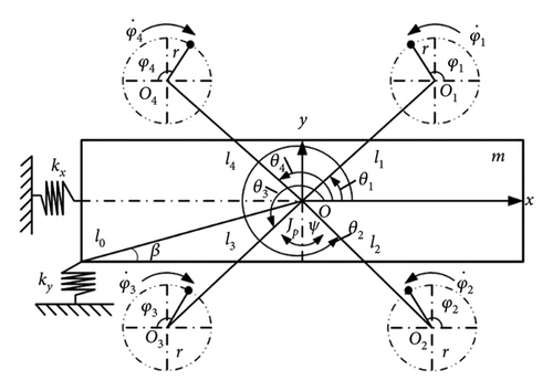
| Symbol | Significance |
|---|---|
| mi | The mass of each ER |
| m0 | The basic mass of ERs |
| Jp | The moment of inertia of the rigid frame |
| m | The mass of the rigid bench |
| J | The moment of inertia of the vibrating system |
| kx, ky, kψ | The stiffness coefficients in the x, y, and ψ directions |
| r | The eccentric radius of the inductor motors |
| M | The total mass of the vibration system |
| fx, fy, fψ | The damping coefficients in the x, y, and ψ directions |
| l1, l2, l3, l4 | The distance between the center of the body and the rotating center |
| f1, f2, f3, f4 | The damping coefficients of the ERs |
| Ji | The moment of inertia of the inductor motor |
| d-, q- | The d-and q-axes in rotor field–oriented coordinate |
| Ls | Self-inductance of the stator |
| Lr | Self-inductance of the rotor |
| Subscript s/r | Stator/rotor |
| Lm | Mutual inductance of the stator and rotor |
| Lks | Leakage inductance of the stator |
| ϕsd/ϕsq | The flux linkages of the stator in the d-/q-axis |
| ϕrd/ϕrq | The flux linkages of the rotor in the d-/q-axis |
| Rs | The stator resistance |
| Rr | The rotor resistance |
| Rks | Equivalent resistance of the stator |
| isd | The current of stator in the d-axis |
| isq | The current of stator in the q-axis |
| ird | The current of rotor in the d-axis |
| irq | The current of rotor in the q-axis |
| ω | The mechanical speed |
| ωs | The synchronous electric angular speed |
| , , , | derivation of ϕsd, ϕsq, ϕrd, ϕrq |
| σ | The leakage factor |
| Tr | A rotor time constant |
| usd | The voltage of stator in the d-axis |
| usq | The voltage of stator in the q-axis |
| urd | The voltage of rotor in the d-axis |
| urq | The voltage of rotor in the q-axis |
| np | The number of pole pairs of the induction motor |
| ω1, ω2, ω3, ω4 | The speeds of four motors |
| φ1, φ2, φ3, φ4 | The phases of four motors |
| θ | Synchronization electric angle |
| Parameters | Values |
|---|---|
| M (kg) | 304 |
| Jp (kg.m2) | 44.5 |
| kx (N/m) | 129,332 |
| ky (N/m) | 105,334 |
| kψ (Nm/rad) | 30,715 |
| fx (Ns/m) | 615.5 |
| fy (Ns/m) | 618 |
| fψ (Nsm/rad) | 180.2 |
| θ1, θ2, θ3, θ4 (°) | 30, 150, 270, 330 |
| m0 (kg) | 6 |
| r (m) | 0.05 |
| l1, l2, l3, l4 (m) | 0.45, 0.45, 0.45,0.45 |
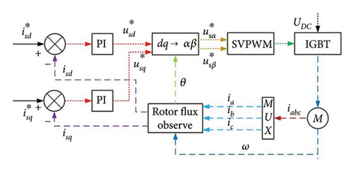
| Parameters | Motor 1 | Motor 2 | Motor 3 | Motor 4 |
|---|---|---|---|---|
| P (kW) | 0.2 | 0.2 | 0.2 | 0.2 |
| np | 3 | 3 | 3 | 3 |
| f0 (Hz) | 50 | 50 | 50 | 50 |
| U/V | 220 | 220 | 220 | 220 |
| n (r/min) | 950 | 950 | 950 | 950 |
| Rs (Ω) | 40.5 | 40.5 | 40.5 | 40.5 |
| Rr (Ω) | 12 | 12 | 12 | 12 |
| Ls (H) | 1.21275 | 1.21275 | 1.2175 | 1.21275 |
| Lr (H) | 1.222 | 1.222 | 1.225 | 1.222 |
| Lm (H) | 1.116 | 1.116 | 1.116 | 1.116 |
| (Wb) | 0.98 | 0.98 | 0.98 | 0.98 |
| f1,2,3,4 (Nms/rad) | 0.005 | 0.005 | 0.005 | 0.005 |
2.2. Stability and Synchronous Conditions
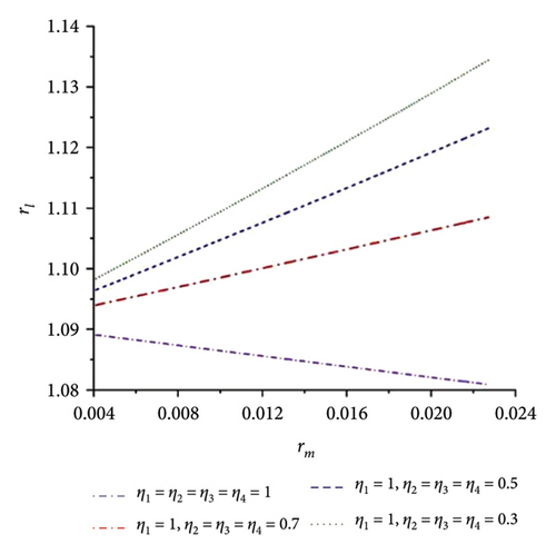
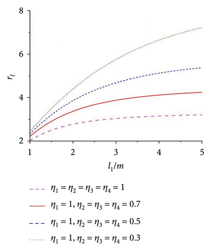
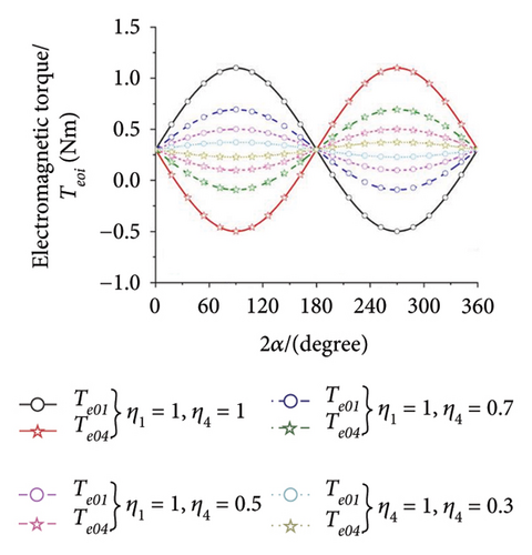
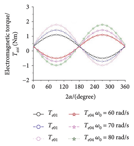
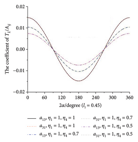
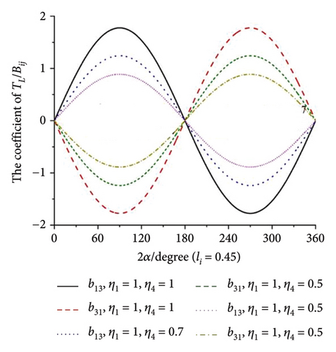
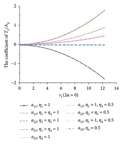
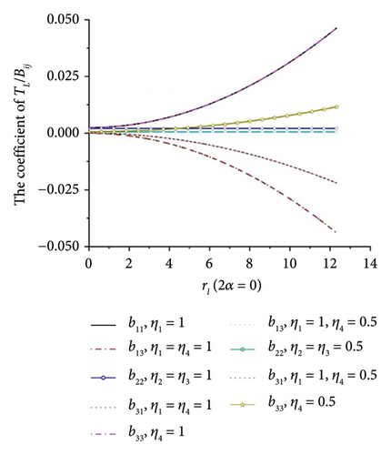
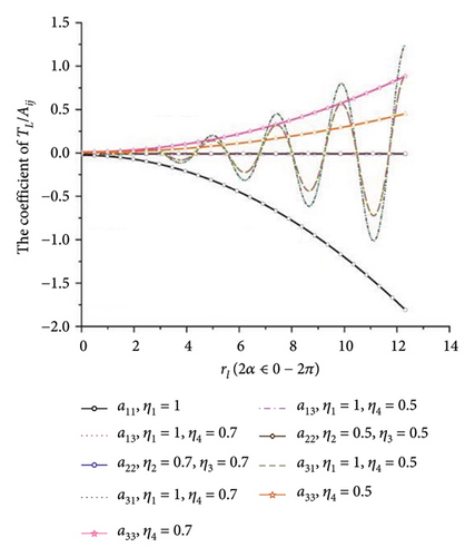
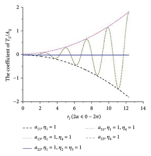
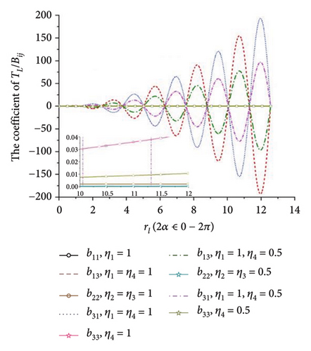
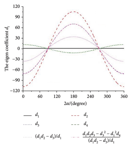
When all the eigenvalues in equation (10) have negative real roots, the synchronous state of four ERs is stable. Otherwise, it is not stable. This result is illustrated in Figure 5(h), and it can be concluded that there is no intersection region of the curves which can satisfy the requirements in equation (11). So, the multifrequency self-synchronization between Motors 1 and 2 cannot be realized, which result in the conclusion in Ref. [31]. To sum up, the multifrequency composite synchronization motion referred in Figure 1 cannot be realized based on the condition of multifrequency self-synchronization between Motors 1 and 2. To realize the multifrequency composite synchronization motion in Figure 1, the multifrequency controlled synchronization motion between Motors 1 and 2 should be realized. Thus, a modified FASM controlling method is proposed.
2.3. The Fuzzy Sliding Model Controller Design
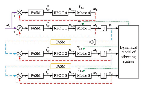

2.4. The Adaptive Controlling Algorithm Design and Stability of the Controlling System
According to the LaSalle invariant set theorem, when and s ≡ 0, only if the time t trends to infinity, then the sliding model surface approaches zero (t⟶∞, s⟶0). Thus, , the controlling system is asymptotically stable.
3. Results
In this section, some numerical simulation examples are given to certify the correctness of the multifrequency composite synchronous theory first. Then, the effectiveness and stability of the controlling method and the arbitrariness of the multifrequency parameter n are both illustrated. The experiment is shown to demonstrate the consistency among the three parts. Finally, the novelty and research contribution are with an in-depth discussion.
3.1. Numerical Simulation Results
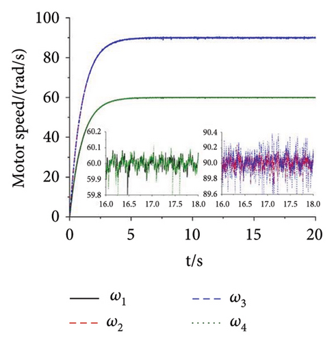
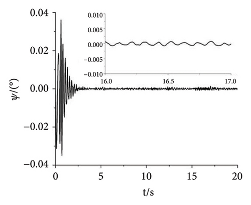
A multifrequency synchronization method is proposed to provide complex trajectories and avoid the issues of blocking and sticking in vibrating screens used in engineering. However, the multifrequency self-synchronization method is difficult to apply to the integrated harvesting and screening machine due to the structure size which is affected by the instinct dynamical feature of the vibrating system. To accommodate the installed requirement, the structure size is reduced with the CI-FASM controlling method. Aiming at the four ERs, fully controlled synchronization incurs significantly higher costs. Therefore, the multifrequency composite synchronization method, which integrates multifrequency controlled synchronization with self-synchronization, is proposed to reduce expenses. The numerical simulation results are shown below. According to the approach of the structure in Figure 6, the initial target speed in Figure 8 is given as 60 rad/s and the multifrequency parameter is shown as n = 1.5. From Figure 8(a), it can be known that the speeds of Motors 1 and 4 are stable at the given speed. The speeds of Motors 3 and 4 both reach 90 rad/s with little floating. This result proves that the synchronous speeds can be realized with ω1 − ω4 = 0, ω2 − ω3 = 0, and 1.5ω1 − ω2 = 0, which is proposed in the “Methods” section. In Figure 8(b), the three groups of phase differences all approach zero, which can be expressed as φ1 − φ4 = 0, φ2 − φ3 = 0, and 1.5φ1 − φ2 = 0. This result indicates that Motors 1 and 4 realize the self-synchronization motion, Motors 2 and 3 realize the controlled synchronization, and Motors 1 and 2 realize the multifrequency controlled synchronization. Thus, the vibrating system realizes the multifrequency composite synchronization. Moreover, compared with the former literature, the proposed CI-FASM controlling method presents better controlling effectiveness which contains smaller tracking errors of the phase and a faster controlling response. Figure 8(c) shows the load torques of four motors which are all between −1.3 and 1.3. This result illuminates that the load torques are lower than the electromagnetic torques which can be calculated with the parameters in the three tables. Thus, the four motors can operate normally and the phenomenon of locked rotor will not occur. Figures 8(d) and 8(e) demonstrate the responses of three directions. Because the two groups of motors both operate in the opposite direction, all the forces in the x direction cancel out with each other. Thus, the response in the x direction is approximately 0, and this result is consistent with the dynamical feature in Figure 1. The response in the y direction is composed of a superposition of amplitudes with two different frequencies. The response in the ψ direction fluctuates around 0°. This result indicates that the rigid body operates with a very little swing angle, and the vibrating system can reach the stable multifrequency composite synchronization which is proposed in the theory part.
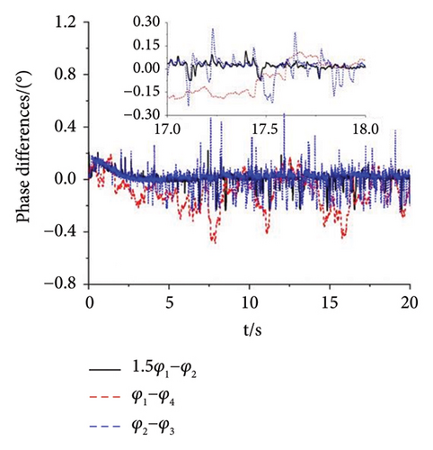
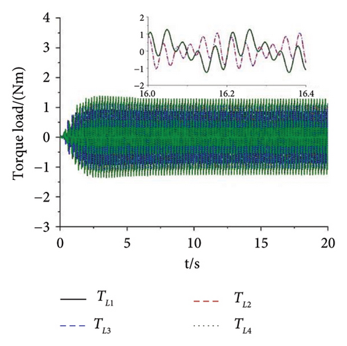
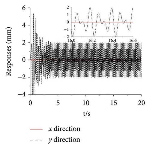
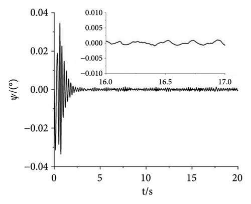
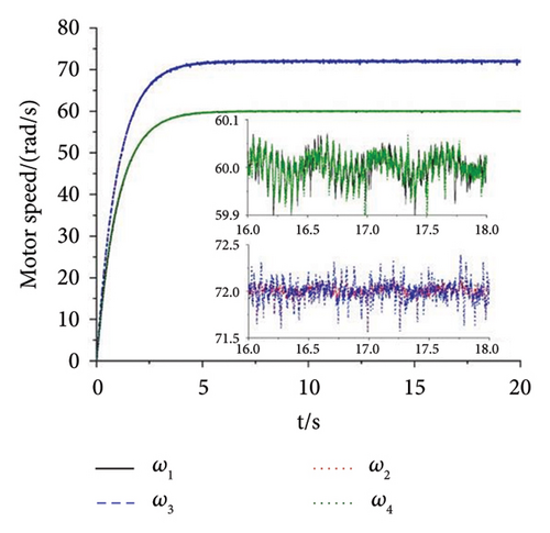
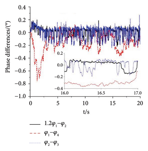
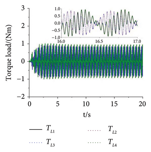
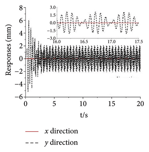
In this numerical simulation example, the multifrequency parameter n is adjusted from 1.5 to 1.2 for certifying its arbitrariness. Figures 9(a) and 9(b) show the speeds and the phase differences of four motors. In Figure 9(a), it provides the result of 1.2ω1 − ω2 = 0, while the result of 1.2φ1 − φ2 = 0 is shown in Figure 9(b). Figure 9(c) reflects the influence of the different multifrequency parameter n. Compared with Figure 8(c), this result indicates that the amplitude of load torque becomes smaller as the parameter n decreases. On the contrary, the amplitude of load torque will become larger as the parameter n increases. Figure 9(d) gives a different response in the y direction. And this result shows the diversity of the motion trajectory of the vibrating system with different multifrequency parameters n. In Figure 9(e), the swing angle ψ still approaches 0, which confirms that the vibrating system reaches the stable multifrequency composite synchronization state. In the meanwhile, the stability and effectiveness of the controlling method and the arbitrariness of parameter n are also proved.
3.2. Experiment Validation
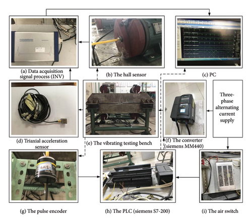
To certify the correctness of the theory proposed, an experiment of the multifrequency composite synchronization is designed as Figure 10. The vibrating testing bench (Figure 10(e)) is installed on the ground. Four inductor motors are, respectively, controlled by four converters (Figure 10(f)) which are powered by the three-phase alternative current supply. Four hall magnetic switches (Figure 10(b)) are, respectively, fixed on the vibrating testing bench corresponding to four motors. Each ER of the four motors is, respectively, stuck with a magnetic patch. When the motor turns one circle, a pulse is transmitted to the INV (Figure 10(a)) which connects with the PC (Figure 10(c)). Four pulse encoders (Figure 10(g)) are installed on a steel frame, and each pulse encoder connects the corresponding motor shaft with a rubber hose. The other side of the pulse encoder is connected to the PLC (Figure 10(h)). Then, the PLC connects to the converter. The air switch (Figure 10(i)) converts the 380 V AC to the 24 V DC and provides it to the PLC. The three-axial acceleration sensor (Figure 10(d)) is fixed on the vibrating testing bench to measure the response amplitude which is transmitted to the INV.
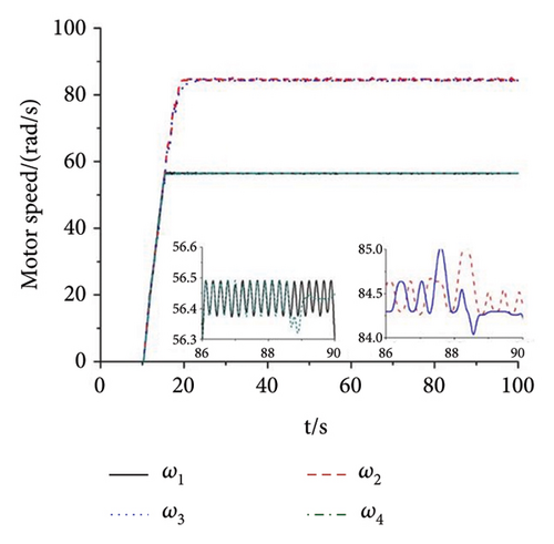
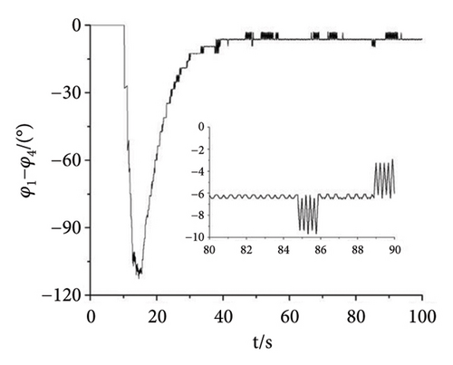
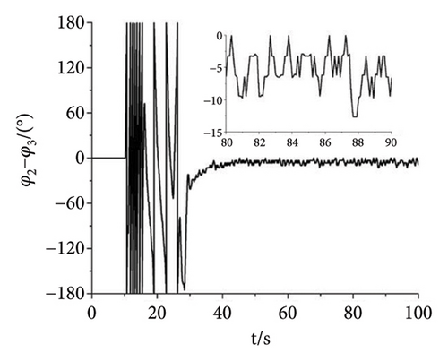
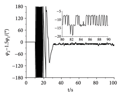
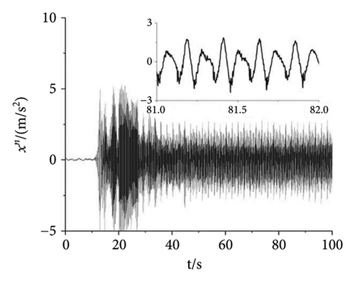
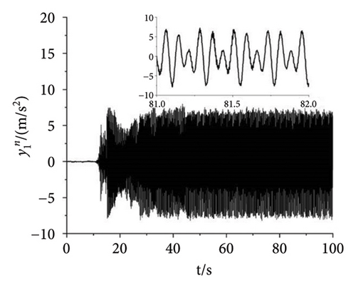
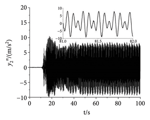
As shown in Figure 11, the experiment with the parameter n = 1.5 is finished to illuminate the correctness of the theory. In the experiment, the power supply frequency of Motors 1 and 4 are set as 27 Hz. The power supply frequency of Motors 2 and 3 are set as 40.5 Hz. Then, the speeds of the four motors can be calculated according to the pole pairs of inductor motors which are given in Table 3. According to the formulation ω = 2πf/np, the speeds of Motors 1 and 4 can be calculated as 56.52 rad/s. Similarly, the speeds of Motors 2 and 3 are 84.78 rad/s. From Figure 11(a), the speeds of Motors 1 and 4 both fluctuate around 56.46 rad/s. The speed error is about (56.52 − 56.46)/56.52 ≈ 1000. It can be recognized that Motors 1 and 4 both realize the synchronous speed. Similarly, the speeds of Motors 2 and 3 fluctuate around 84.5 rad/s and the error is about 3000%. Figures 11(b), 11(c), 11(d) present the phase differences of four motors. The absolute phase difference between Motors 1 and 4 is about 6°. Compared with the theory φ1 − φ4 = 0, this result can be deemed that Motors 1 and 4 realize self-synchronization in engineering. The absolute phase difference between Motors 2 and 3 fluctuates around 5°. Thus, Motors 2 and 3 realize the controlled synchronization with zero phase difference, which verifies the theory assumption φ2 = φ3 in the model of multifrequency composite synchronization. The absolute phase difference between Motors 1 and 2 is about 13°, which is consistent with the theory nφ1 − φ2 = c. Figures 11(e), 11(f), 11(g) show the responses of the vibrating system. The response in the x direction is much smaller than it is in the y direction. This result is consistent with the theory in Equation (2) and the numerical simulation shown in Figure 8(d). Moreover, the curves in Figures 11(f) and 11(g) have the same tendency as the curves in Figure 8(d). According to the results above, the multifrequency composite synchronization can be realized with proposed CI-FASM controlling method.
4. Discussion
Combined with the numerical simulation and experiment results, the multifrequency composite synchronization method can be implemented. In the meanwhile, it is possible to screen different kinds of materials by adjusting the fixed frequency ratio parameter n. It is proved that the proposed method can be applied to multiple frequency vibrating screens in engineering.
The mainstay of the proposed method is first to confirm whether the miniaturized dynamic model presented in this paper can be achieved through the multifrequency self-synchronization method. If the multifrequency self-synchronization is suitable for the miniaturized vibrating screen system, the control method proposed in this paper becomes irrelevant. According to documents [26, 27], the synchronization becomes better with decreasing rl. When ηi = 1, the mass of four ERs equal with each other and rl < 1.09. Conversely, when ηi ≠ 1, the synchronism of the vibrating system is worse. This result is also reflected in Figure 5. This result indicates that when ηi = 1, rl has the minimum value, the vibrating system will acquire the best self-synchronization condition. Thereby, the condition ηi = 1 is applied in the synchronization analysis. According to the Hurwitz condition in Figure 5(h), although parameters suitable for multifrequency self-synchronization are used, the multifrequency self-synchronization based on the dynamic model described in this paper still cannot be achieved. Then, it is necessary to apply control methods to the dynamical model. In addition, according to documents [21, 22], synchronization with the same frequency that aims to enlarge the amplitude of the vibrating system can usually only achieve the screening of a single material. The screening effect of mixed materials is not ideal in engineering.
By introducing the master–slave control strategy and the CI-FASM control algorithm, the multifrequency composite synchronization and the arbitrariness of the parameter n are realized. Compared Figure 8(d) with Figure 9(d), different parameter n shows different responses. This result indicates that the method proposed in this paper can give a suitable fixed frequency ratio for various or mixed materials to obtain a better screening process. Although the document [31] solves the problems above, there are many electrical equipment, which lead to high costs. Then, the control method in document [31] is hard to satisfy the stability of the dynamical model in this paper. Compared with the former literature [21, 22, 28–31], the proposed CI-FASM method presents better control effectiveness as well as smaller tracking phase errors. The multifrequency composite synchronization method is used to reduce the electrical equipment and finally reduce the cost.
During the experiment, there may be a resonance phenomenon between the motors and the vibration system, which can lead to a blocking phenomenon of the motors. The motors’ frequencies are so low that the energy is not enough, and the jump phenomenon of near resonance (Sommerfeld effect) will appear. This is not beneficial for the controlling result. So, the motors’ frequencies should be well chosen and suitable for the converters in Figure 10(f). Besides that, the structural vibration characteristics of the vibration system are also not taken into account. The modal response of multiple frequencies to vibration systems is not fully considered. We will consider and investigate this feature in our future study.
5. Conclusions
- 1.
This article investigates the multifrequency composite synchronization of four ERs in a vibrating system. The feature analysis of the dynamical model is discussed. The controller is designed by associating the master–slave strategy with the CI-FASM controlling method, and its stability is proved by the Lyapunov criterion and the LaSalle invariant set theorem.
- 2.
Aiming to address the drawbacks of multifrequency self-synchronization and multifrequency controlled synchronization, the method proposed in this paper not only achieves the noninteger multifrequency synchronization of four ERs but also reduces the cost of the vibrating system by decreasing the electrical equipment.
- 3.
Based on the proposed CI-FASM controlling method in the simulations and experiment, the speed error between Motors 1 and 4 is 1000% and the speed error between Motors 2 and 3 is 3000%. The phase difference between Motors 2 and 3 is approximately 0. And the phase difference between Motors 1 and 2 is equal to a constant. Compared with the existing research results in the references, the results in this paper indicate that the proposed method is more stable and effective, and this method can realize close tracking with less overshoot and oscillation.
- 4.
By discussing the arbitrariness of the parameter n, mixed materials with different shapes and viscosity can match the suitable frequency for effective vibrating screening. The proposed method provides a new reference for multifrequency screening equipment.
- 5.
To realize multifrequency composite synchronous motion with four ERs, two motors are controlled in this paper. To further reduce the cost of electrical equipment, the multifrequency composite synchronization motion can be realized based on one motor controlled by an adjustment dynamics model. It is essential to consider the stability of the dynamical model. While Motors 1 and 2 realize the multifrequency controlled synchronization, Motors 2 and 3 should realize the self-synchronization with the same frequency. Because Motor 2 traces Motor 1 first, there is a hysteretic result in the self-synchronization between Motors 2 and 3, which makes it difficult to realize the stable self-synchronization between Motors 2 and 3.
Conflicts of Interest
The authors declare no conflicts of interest.
Author Contributions
Lei Jia wrote the article, Qingsong Chang compiled the figures and tables, Yang Tian led the experiments, Xin Zhang checked the article, and Ziliang Liu conducted the simulation.
Funding
The author’s research was supported by 2022 Liaoning Education Department General Project (Project No. LJKMZ20220602).
Appendix A: The Coefficient Items of Small Parameters
Appendix B: The Coefficient at the Expansion Points of Taylor
Appendix C: The Eigenvalue Coefficient
Open Research
Data Availability Statement
The data that support the findings of this study are available from the corresponding author upon reasonable request.


