Integrated Floating Slab Dynamic Vibration Absorber Based on Tuned Liquid Particle Damping: Theory, Modeling, and Experimentation
Abstract
As subway train-induced low-frequency vibrations continue to rise, there is an increasing need for more effective vibration control strategies. Although current low-frequency vibration reduction methods offer some solutions, further progress is necessary. This paper introduces a novel tuned liquid particle damper-dynamic vibration absorber (TLPD-DVA), which merges the principles of tuned liquid dampers (TLDs) and particle dampers (PDs). By capitalizing on the low-frequency damping capabilities of TLDs, this approach incorporates particles suspended within the liquid to create a hybrid damping device capable of effectively attenuating vibrations across a wide low-frequency range (10 to 80 Hz). A discrete element method-computational fluid dynamics (DEM-CFD) model for multiphase flow is employed to explore the damping mechanism, optimize system parameters, and develop a frequency-dependent nonlinear damping device. The TLPD-DVA is then applied to floating slab track systems to control low-frequency vibrations, and a dynamic interaction model involving the coupled vehicle-TLPD-DVA-floating slab track-tunnel system is established to assess the system’s response. Harmonic response analysis of a floating slab track fitted with TLPD-DVAs, along with dynamic mass and mass ratio indices, clarifies the vibration reduction mechanism. Additionally, field tests demonstrate that the TLPD-DVA reduces vertical acceleration on the floating slab by up to 8 dB and on the tunnel wall by up to 10 dB within the low-frequency range, surpassing the performance of tuned DVAs. The proposed TLPD-DVA offers significant potential for vibration control in various civil engineering applications, including transportation infrastructure, building foundations, and vibration-sensitive facilities.
1. Introduction
The low-frequency vibrations induced by subway trains constitute a prominent environmental concern. As subway trains run on the tracks, the interactions between the wheels and rails cause vibrations in the track structure. These vibrations can propagate through the surrounding structures and soil, reaching nearby buildings and affecting their serviceability by disrupting sensitive equipment, human comfort, and normal building functions [1, 2]. While such vibrations typically do not compromise the structural integrity of buildings, they can severely affect functionally sensitive environments, particularly when subway lines pass near facilities such as concert halls, hospitals, museums, or buildings housing precision instruments [3, 4]. To mitigate the negative impacts to the maximum extent, various track vibration reduction measures have been developed. Among them, the steel-spring floating slab track (FST) is considered to have excellent vibration reduction performance and is used in track sections with the most stringent vibration reduction requirements [5, 6]. Vogiatzis and Kouroussis [7] conducted on-site measurements on a segment of the steel-spring FST in the Athens Metro, revealing that the FST effectively reduced environmental vibrations above 40 Hz. However, in the lower frequency range below 20 Hz, the FST not only failed to diminish vibrations but, in fact, could develop resonance due to the proximity to the fundamental frequency of the FST, amplifying the vibration response. This behavior has been consistently demonstrated in several other studies [8, 9]. We can conceptualize the floating slab and its isolators as a mass-spring-damper system inserted between the track and other structures. The mass is provided by the floating slab, while the vertical stiffness is provided by the steel-spring isolators. This configuration utilizes the inertia of the floating slab to counterbalance the dynamic loads transmitted through the fasteners. The frequency range at which the steel-spring FST provides isolation should be greater than times the natural frequency of the floating slab, but this produces less pronounced suppression of low-frequency vibrations below 20 Hz [6]. The conventional approach involves reducing the natural frequency of the track system by either using smaller support stiffness or heavier floating slabs. However, on the one hand, the effectiveness of adopting larger floating slabs for vibration isolation is limited due to spatial constraints and construction costs associated with subway track installations, and, on the other hand, reducing support stiffness results in a significant increase in the vertical displacement of the track, posing a potential threat to the operational safety of subway trains. Thus, it can be concluded that the traditional methods fail to offer a solution for low-frequency vibration reduction. Therefore, developing alternative solutions that can effectively suppress vertical low-frequency vibrations of FST structures is of great significance.
The low-frequency vibrations in the steel-spring FST system can be effectively mitigated using dynamic vibration absorbers (DVAs), enhancing low-frequency vibration reduction and suppressing vibration amplification at natural frequencies [10–12]. Compared to novel vibration isolation measures like quasi-zero stiffness isolators [13, 14] and magnetorheological dampers [15], DVAs have a simple structure and are easy to install and maintain. However, the effectiveness of traditional floating slab DVAs is limited, as achieving significant low-frequency vibration reduction often requires heavy DVAs. Given the spatial constraints of subway track installations and the adverse effects of excessive mass on floating slab stability, modifying traditional floating slab DVAs by integrating other vibration reduction technologies is essential. The tuned liquid damper-DVA (TLD-DVA) is a simple and practical concept for vibration suppression. It consists of a rigid container partially filled with liquid, where vibrations cause the liquid to oscillate, generating an inertial force opposing dynamic loads and reducing the container’s response. TLD-DVAs are widely used in civil, mechanical, and electrical engineering systems [16–18]. Their advantages include effectiveness in the low-frequency range, operation under small displacements, low failure rates, ease of optimization, and low installation and maintenance costs [19]. Although TLDs have been extensively studied for horizontal vibration control, particularly in building seismic resistance, they also have the potential for vertical vibration suppression. Recent studies have demonstrated that TLDs can effectively mitigate vertical vibrations in various structural systems. For instance, Yan and Lei [20] investigated the feasibility of using TLDs to reduce both vertical and horizontal vibrations in railway elevated box girder bridges, showing that the vertical vibration amplitude of web and flange plates decreased by about 40%, while noise radiation near the web was reduced by 2-3 dB. Additionally, Ikeda [21] analyzed the nonlinear coupling of TLDs under vertical sinusoidal excitation and found that the vertical vibration amplitude of the structure significantly decreased, with liquid subharmonic oscillations further enhancing the damping effect. These studies indicate that TLD technology can be effectively applied to vertical vibration control, making it a promising approach for mitigating FST vibrations. However, many TLD-DVAs struggle to suppress mid-to-high-frequency vibrations and noise because only part of the liquid contributes to vibration reduction [22]. Enhancing damping often requires larger TLD-DVAs or tuning the liquid’s oscillation frequency to match the main structure’s natural frequency. Common liquids like water have low viscosity, prompting the use of high-viscosity liquids or damping materials [23], or the addition of damping baffles to increase energy dissipation [24–26]. In some studies, such as Soliman et al. [24] and Zahrai et al. [25], semiactive or rotating baffles have been proposed to enhance damping performance by adjusting the screen angle in real time. However, in other works such as Warnitchai and Pinkaew [26], fixed damping elements like rods, plates, or mesh screens are used without any rotation, and damping is achieved through flow resistance and pressure drop. Despite these enhancements, high-viscosity liquids are sensitive to environmental conditions, while moving parts such as rotating baffles may reduce system lifespan and complicate maintenance. Furthermore, in FST systems, the structural displacement amplitude is typically limited, which affects the full activation of liquid sloshing energy dissipation in TLD-DVAs, further constraining their performance.
The particle damper-DVA (PD-DVA) is a low-cost, effective vibration suppressor that dissipates energy through inelastic collisions and friction between solid particles within its cavity and the container’s inner walls [27, 28]. Widely studied and applied in civil, mechanical, and aerospace fields, PD-DVA offers a broader effective frequency range for suppressing mid-to-high-frequency vibrations in multi-degree-of-freedom (DOF) systems compared to TMD-DVA and TLD-DVA, though it is less effective in the low-frequency range [29–31]. A challenge lies in its complex energy dissipation mechanism and nonlinear behavior, which complicates accurate characterization. While various models, such as multiparticle impact [32], particle dynamics-based [33], and equivalent viscous damping models [34, 35], have been proposed, they rely on numerous assumptions, limiting their real-world applicability. Recent advancements in numerical methods, particularly the discrete element method (DEM), have enabled more accurate simulations of particle behavior in PD technology [36, 37].
Currently, extensive research has been conducted on PD-DVA and TLD-DVA, demonstrating that TLD technology is effective in mitigating vibrations in the low-frequency range, while PD technology performs better in the mid-to-high-frequency range. As a result, researchers have explored the potential for combining these two technologies to achieve vibration reduction across a broader frequency spectrum [38]. Due to the complex motions of liquid and particles within DVAs, their performance is highly influenced by various factors, such as particle material, particle size, particle fill ratio, type of liquid, liquid viscosity, liquid height (LH), excitation frequency, and vibration amplitude. Although preliminary experimental studies on the concept of tuned liquid particle damper (TLPD) technology exist [39], its practical engineering application, particularly in large-scale multi-DOF systems like subway FSTs, has not been fully explored. In particular, key aspects such as coupled numerical modeling of the gas-liquid-particle damping mechanism, parameter optimization under spatial constraints, and system-level integration into realistic railway environments remain insufficiently addressed.
- •
The first integration of TLPD-DVA into a full-scale FST system.
- •
The development of a DEM-CFD–based gas-liquid-particle multiphase flow simulation model to quantify nonlinear damping behavior.
- •
The introduction of a modal-equivalent mass identification approach combined with extended fixed-point theory for absorber parameter design in multi-DOF systems.
- •
Full-scale experimental validation to verify and complement theoretical predictions.
The TLPD-DVA is designed to suppress low-frequency vibrations and mitigate dynamic energy transmission to the underlying foundation, and its performance is comprehensively evaluated through numerical simulations and field testing, ensuring both theoretical rigor and engineering applicability. In the second part of the study, based on the equivalent mass identification method and extended point theory for multi-DOF systems, the optimal parameters for the floating slab-vibration absorber system are found using the parameters of a short steel-spring FST and its modal analysis. In the third section, the parameters of the tuned liquid-particle damping system are optimized using the proposed DEM-computational fluid dynamics (DEM-CFD) gas-liquid particle-fluid multiphase flow simulation model, resulting in the design of a variable-frequency nonlinear TLPD-DVA device. In the fourth section, a harmonic response analysis of the steel-spring FST system equipped with TLPD-DVAs is conducted to explore the vibration reduction mechanism of TLPD-DVA in greater depth. The fifth section analyzes the dynamic vibration characteristics of TLPD-DVA under dynamic train loads by establishing a coupled vehicle-TLPD-DVA-floating slab-track-tunnel dynamic analysis model. In the sixth section, on-site tests are performed on the developed TLPD-DVA and the results are compared to dynamic analysis outcomes to further elucidate and validate the reliability and dynamic performance of the TLPD-DVA for suppressing low-frequency vibrations.
2. TLPD-DVA Design
2.1. Design Principle and Method of DVA for Continuous System
The working principle of traditional tuned DVAs (T-DVAs) involves attaching a secondary structure with resonant characteristics to the primary structure. By tuning the frequencies of the primary and secondary structures, the vibrational energy of the primary structure is transferred to the secondary structure and dissipated there reducing the vibrational response of the primary structure. This design method for DVAs is referred to as the extended point theory for single-degree-of-freedom (SDOF) systems [40–42]. However, since the steel-spring FST is a continuous system with multiple vibration modes, the design method of the traditional SDOF system DVAs cannot be directly applied. Nevertheless, a continuous distributed system can be discretized into a multi-DOF system and then transformed into a collection of SDOF systems using modal analysis and equivalent mass identification methods. Subsequently, the extended point theory for SDOF systems can be applied to design a DVA for the steel-spring FST system [12].
The modal analysis method plays a significant role in the analysis of multi-DOF systems. However, parameters such as modal mass and stiffness do not have direct physical quantities. Therefore, for vibration control methods like DVAs that require design in physical coordinates, direct application is not possible. To address this, the concept of equivalent mass with physical meaning is introduced here, and a method is proposed to derive uncoupled equations in physical coordinates.
In modal analysis, the characteristic vectors represent relative values of deformations and do not have a direct physical interpretation in terms of absolute amplitudes. Hence, the modal mass and modal stiffness matrices obtained from orthogonalizing the physical mass and stiffness matrices are not unique and have no physical meaning. It is thus necessary to assign physical meaning to these modal characteristics. By scaling the mode shape such that the displacement at a selected DOF is equal to 1, the characteristic vector can be used to obtain the equivalent mass with physical meaning at that position for a multi-DOF system. With this method, after obtaining the SDOF equivalent masses for each mode, the corresponding equivalent stiffness and equivalent damping are also determined.
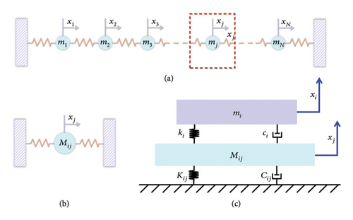
According to the principles of modal analysis, an N-DOF system can be regarded as a collection of N uncoupled individual SDOF systems, as illustrated in Figure 1. In other words, the N-DOF system shown in Figure 1(a) can be considered as an assembly of the SDOF systems depicted in Figure 1(b).
From the above equation, it is evident that the ratio of modal deformations is constant, and hence the equivalent mass is determined. When mass j is at the position of maximum deformation of the mode, the obtained equivalent mass is minimal. Conversely, when mass j is at the node of the mode (where deformation is zero), the equivalent mass becomes infinite.
In equations (9)–(11), μi is the mass ratio between the DVA and the equivalent modal mass Mij of the steel-spring FST at the corresponding location for the ith mode; mi, ki, and ci represent the mass, optimal stiffness, and optimal damping of the DVA corresponding to the nth mode of the FST, respectively. Zij and ζij denote the equivalent damping ratios of the FST and the absorber at observation point j, for the nth mode.
This comparison reveals that when the equivalent damping of the FST is zero, Zij = 0, equation (10) reduces to equation (12), and when the equivalent damping Zij ≠ 0, the optimal stiffness obtained from equation (10) is smaller than that from equation (12). Therefore, in practical design, equation (12) can be used to estimate an initial value for the optimal stiffness. This initial value can then be slightly reduced based on the optimal tuning condition, which aims to make the two fixed points on the frequency response curve equal in height. The adjusted value is taken as the final optimal stiffness of the absorber. Once this is obtained, it can be substituted into equation (11) to calculate the corresponding optimal damping.
2.2. Modal Analysis of Steel-Spring FST
The significant increase in vibration amplitude of the steel-spring FST system in the low-frequency range is caused by structural resonance. Therefore, before designing the DVA, it is necessary to determine the natural frequency and mode shapes of the steel-spring FST.
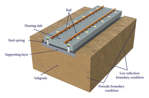
As shown in Figure 2, a coupled model of the steel-spring FST system was established using the multiphysics simulation software COMSOL Multiphysics. The FST has a length of 9 m, a width of 3 m, and a thickness of 0.5 m. The supporting layer of the floating slab has a length of 9 m, a width of 3 m, and a thickness of 0.3 m. The foundation has a length of 9 m, a width of 6.4 m, and a height of 3 m. These parameters are widely adopted in various urban rail transit projects and are capable of meeting the requirements for train stability and vibration control [5–7]. The steel rails, floating slab, supporting layer, and foundation are simulated using solid elements. Floquet periodic boundary conditions are applied at both ends, and low reflective boundary conditions are applied at the bottom and sides of the foundation, whereas the outermost layer of nodes is fixed. The Floquet periodic boundary condition applied in the model introduces a phase factor that differentiates the field values between the source and target boundaries, which is determined by the relative distance between the wavevector and the boundary. When dealing with physical problems that are periodic in space or time, the use of this boundary condition can simplify complex simulations into periodic units, greatly reducing the amount of computation without losing accuracy. The low-reflection boundary conditions used in the model employ material data from neighboring domains by default, creating a perfect impedance match for both pressure and shear waves. The fastening system and the steel-spring isolators are modeled using spring-damper elements. The structural parameters of the steel-spring FST system are listed in Table 1.
| Components | Parameter | Unit | Value |
|---|---|---|---|
| Rail | Elastic modulus | GPa | 206 |
| Density | kg/m | 60.64 | |
| Poisson’s ratio | — | 0.3 | |
| Rail fastener | Vertical stiffness | kN/mm | 45 |
| Vertical damping | kN·s/m | 25 | |
| Lateral stiffness | kN/mm | 45 | |
| Lateral damping | kN·s/m | 25 | |
| Floating slab | Length × width × depth | m × m × m | 9 × 3 × 0.5 |
| Elastic modulus | GPa | 36.5 | |
| Density | kg/m3 | 2500 | |
| Poisson’s ratio | — | 0.2 | |
| Steel spring | Vertical stiffness | kN/mm | 5.3 |
| Vertical damping | kN·s/m | 11.4 | |
| Lateral stiffness | kN/mm | 4.9 | |
| Lateral damping | kN·s/m | 10 | |
| Shear hinge | Shear stiffness | N/m | 5 × 10⁹ |
| Supporting layer | Length × width × depth | m × m × m | 9 × 3 × 0.3 |
| Elastic modulus | GPa | 32.5 | |
| Density | kg/m3 | 2440 | |
| Poisson’s ratio | — | 0.24 | |
| Subgrade | Length × width × depth | m × m × m | 9 × 6.4 × 3 |
| Elastic modulus | MPa | 500 | |
| Density | kg/m3 | 1900 | |
| Poisson’s ratio | — | 0.25 | |
| Tunnel (Section 5.1) | Length | m | 55.5 |
| Outer diameter | m | 3 | |
| Lining thickness | m | 0.3 | |
| Tunnel invert thickness | m | 0.8 | |
| Elastic modulus | GPa | 31.5 | |
Shown in Figure 3 are the first four modal shapes of the floating slab. The first mode is dominated by vertical translational motion of the floating slab, the second and third modes primarily involve rotation about the centerline of the floating slab, and the fourth mode is characterized by the first-order vertical bending resonance of the floating slab.

2.3. Structural Design of TLPD-DVA
Considering the amplified vibration response observed in the frequency ranges near 10 Hz and 30 Hz in the steel-spring FST [7–9], along with the modal analysis in Section 2.2, the 1st mode is identified as the primary target for DVA design due to its dominant contribution to low-frequency vibrations. Additionally, the 4th mode warrants attention due to its relevance to the vertical bending resonance of the steel-spring FST.
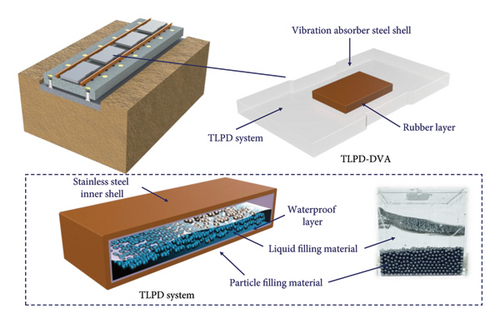
Using equations (3)–(8) and the modal analysis results of the steel-spring FST, the equivalent mass and stiffness of relevant modes of the floating slab can be calculated. Constrained by the spatial limitations of the steel-spring FST system and the equipment layout requirements of urban rail transit systems, the height of the DVA must remain within 93–150 mm below the top surface of the rail, and DVAs are to be installed between the two rails. This height range is specified based on standard clearance requirements for track-mounted equipment such as balises [43]. These devices are typically installed between the rails and must maintain a certain vertical clearance to avoid interference with passing trains. Since the DVA shares the same installation zone, it must conform to the same space constraints. The specific range of 93–150 mm reflects variations across different metro systems, vehicle structures, and track configurations. Taking the mass ratio of the DVA to the floating slab as 0.1, the optimal design stiffness and damping of the DVA can be calculated using equations (9)–(11). The mass of a single DVA is 2709.5 kg, with an optimal design stiffness of 9.5 kN/mm and an optimal design damping of 98.5 kN⋅s/m. The dimensions are length of 1.8 m, width of 1.28 m, and height of 0.15 m, with a centrally reserved space of length 0.6 m, width of 0.4 m, and height of 0.1 m for the TLPD system. The TLPD-DVA consists of three parts from outside to inside: the absorber steel shell, rubber layer, and TLPD system. The schematic diagram of its structure is shown in Figure 4. The material parameters of each component are listed in Table 2. The material parameters listed in Table 2 are obtained from the respective manufacturers of the components used in the TLPD-DVA. These parameters were specifically provided by the manufacturers to ensure accuracy and reliability. Furthermore, the listed material properties were directly applied to the finite element model established in this study. The design of the TLPD system parameters will be detailed in Section 3.
| Component | Density (kg/m3) | Elastic modulus (MPa) | Poisson’s ratio | Loss factor |
|---|---|---|---|---|
| Vibration absorber steel shell | ρ1 = 7850 | E1 = 206, 000 | v1 = 0.30 | η1 = 0 |
| Rubber layer | ρ2 = 1300 | E2 = 28 | v2 = 0.47 | η2 = 0.2 |
| Stainless steel inner shell | ρ3 = 7900 | E3 = 206, 000 | v3 = 0.30 | η3 = 0 |
| Waterproof layer | ρ4 = 1200 | E4 = 350 | v4 = 0.25 | η4 = 0.05 |
| Particle filling material | ρ5 = 2700 | E5 = 70 | v5 = 0.34 | η5 = 0 |
| Liquid filling material | ρ6 = 1000 | E6 = 2.2 | v6 = 0.50 | η6 = 0.1 |
3. Selection of TLPD System Parameters
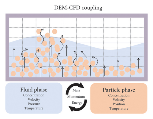
After determining the design parameters of the DVA, it is necessary to make targeted improvements to the tuned dynamic absorber. The concept of TLPD-DVA, as an enhancement to TLD-DVA and PD-DVA, mainly involves leaving a small cavity in the T-DVA and then filling it with a certain amount of liquid and metal particles. However, the material, size, and quantity of solid particles, as well as the filling rate and type of liquid, are currently mostly selected based on experiments [44, 45]. This often requires expensive testing and a considerable amount of time. Therefore, this study establishes a numerical simulation model to analyze the energy dissipation of gas-liquid-particle multiphase flow. The model is illustrated in Figure 5(a).

3.1. DEM-CFD Gas-Liquid-Particle Multiphase Flow Simulation Model
This section introduces the overall algorithmic framework of the DEM-CFD model, illustrated in Figure 5(b). The commercial software packages ANSYS FLUENT and EDEM were employed with secondary development to construct the DEM-CFD gas-liquid-particle multiphase flow simulation model. At the commencement of simulations, ANSYS FLUENT invokes a defined initialization function, which utilizes the EDEM API to specify particle positional information and compute the grid porosity along with the fluid-particle interaction forces. In EDEM, the particle velocities and positions are updated by solving equations (S1-1) and (S1-2) from Supporting Information S1, including the source terms for particle-fluid interaction forces. Based on the updated particle states, calculations are performed for grid porosity and particle-fluid interaction forces. Subsequently, the computation cycle proceeds to iteratively solving a set of equations, including the volume fraction equation (S1-5), fluid control equations (S1-9) and (S1-10), and a series of momentum source term equations in ANSYS FLUENT. Once the iterations converge, the state of fluid cells and free surfaces is updated. The calculation cycle then returns to the EDEM module, where, based on the new fluid velocity field, particle-fluid interaction forces are recalculated. This iterative process continues until the entire simulation is completed.
3.2. Validation of Coupled Simulation Reliability
To verify the reliability of the coupled DEM-CFD gas-liquid-particle multiphase flow model proposed in Section 3.1, a numerical model was established based on the experimental parameters reported in reference [39]. The specific modeling parameters are provided in Table 3. Figure 6 compares the free-vibration velocity responses of three different damping systems—TLPD, PD, and TLD—under an initial displacement condition of A0 = 6 mm. It can be observed that the PD system (green curve) and TLD system (blue curve) exhibit significantly slower attenuation rates compared to the TLPD system (red curve), highlighting the superior energy dissipation capability of the TLPD system. Although minor discrepancies exist between the numerical simulation and the numerical results reported in the literature, the attenuation trend of the coupled simulation aligns closely with the experimental observations in [39]. In particular, the coupled model shows better agreement with the experimental curves in terms of response velocity and damping behavior, thereby validating the accuracy and reliability of the proposed DEM-CFD framework for simulating particle-liquid damping systems. Furthermore, the model demonstrates the capability to output reliable load responses induced by translational motion, confirming its effectiveness in capturing the dynamic characteristics of such systems.
| Components | Parameter | Unit | Value |
|---|---|---|---|
| Shell structure | Mass | kg | 0.34 |
| Density | kg/m3 | 1200 | |
| Spring stiffness | N/m | 2.91 × 10² | |
| Material damping | N·s/m | 3.81 × 10⁻³ | |
| Container diameter | m | 4.4 × 10⁻² | |
| Container height | m | 1.0 × 10⁻¹ | |
| Poisson’s ratio | — | 0.35 | |
| Young’s modulus | Pa | 3 × 10⁹ | |
| Particle | Density | kg/m3 | 2700 |
| Poisson’s ratio | — | 0.33 | |
| Young’s modulus | Pa | 7 × 10¹⁰ | |
| Diameter | m | 6 × 10⁻³ | |
| Number | — | 100 | |
| Liquid | Density | kg/m3 | 1000 |
| Viscosity | Pa·s | 8.9 × 10⁻⁴ | |
| Volume | mL | 30 | |
| Particle-particle | Coefficient of restitution | — | 0.5 |
| Coefficient of static friction | — | 0.0018 | |
| Coefficient of rolling friction | — | 0.001 | |
| Particle-shell structure | Coefficient of restitution | — | 0.65 |
| Coefficient of static friction | — | 0.012 | |
| Coefficient of rolling friction | — | 0.01 | |
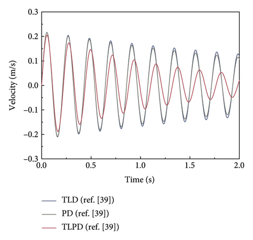
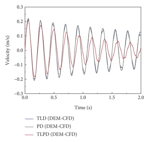
Although the velocity response obtained from the simulation in Figure 6(b) shows some deviation in amplitude compared to the numerical results presented in Figure 6(a), its attenuation trend aligns more closely with the experimental observations reported in reference [39]. In particular, the coupled model demonstrates better agreement with the experimental curves in terms of response velocity and damping characteristics, further confirming the accuracy and applicability of the proposed model for simulating such particle-liquid coupled damping systems. Moreover, the model is capable of stably outputting load responses associated with translational vibration, indicating its strong predictive capability in dynamic analyses.
3.3. TLPD-DVA Energy Loss Factor Calculation
When the dissipated power is known, the energy loss factor can be used to predict the energy dissipation effectiveness of the secondary structure connected to the primary structure. In this section, the steady-state power flow method [46] is employed to calculate the average dissipated power and energy loss factor for different particle and liquid combinations, which serve as performance indicators for assessing the energy dissipation performance of the DVA.
Using the DEM-CFD gas-liquid-particle multiphase flow simulation model, the excitation force F(t) and excitation velocity V(t) acting on the secondary structure due to the primary structure motions can be obtained.
The DEM-CFD numerical simulations of gas-liquid-particle multiphase flow informed the TLPD system design described in Section 3.1. Specifically, the DEM-CFD simulations enabled a detailed parametric analysis of the energy dissipation behavior for various combinations of liquid levels and particle sizes under low-amplitude, low-frequency excitation. By computing the energy loss factor and equivalent damping ratio across these configurations, the simulation identified the optimal particle-liquid gradation that maximized damping performance within the 10–80 Hz range. This data-driven optimization directly guided the selection of key TLPD system parameters—such as particle radius (PR) and LH—used in the final TLPD-DVA configuration. The excitation amplitude (0.002 m) and frequency range (10–80 Hz) were chosen to reflect the realistic displacement conditions and frequency content of the FST under subway operation. Based on reference [48], the particle filling rate for all cases studied herein was assumed as 80%. Figure 7 shows the simulation results of the excitation force applied by the main structure to the TLPD system when the LH was 0.05 m (total container height was 0.1 m), and the filling PRs were 4, 5, and 6 mm, respectively.
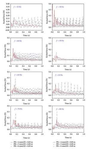
Figure 8 shows the simulation results for the excitation velocity applied by the main structure to the TLPD system when the LH was 0.05 m and the filling PRs were 4, 5, and 6 mm, respectively. As shown in Figures 7 and 8, during the initial simulation phase, the numerical curves fluctuate significantly because the particles and the liquid are in a stationary state during the initial phase, and after the excitation is given, the whole TLPD system starts to vibrate, and the particles and the liquid change from a stationary state to a vibrating state, which generates a large amount of energy exchange during the initial phase, resulting in significant fluctuations in the numerical curves.
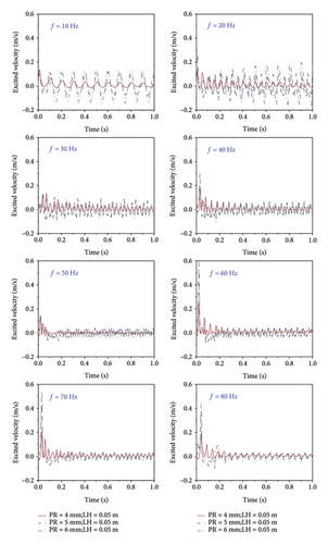
To comprehensively investigate the energy dissipation capability of the TLPD system, we extracted the excitation velocity and excitation force imposed onto the TLPD system by the main structure. These values were then substituted into equations (16) and (19). In total, we analyzed results for three different LHs and three different PRs, resulting in nine different computational scenarios for the calculation of energy loss factor and equivalent damping ratio.
Figure 9(a) shows the energy loss factors of the TLPD system with PRs of 4, 5, and 6 mm without liquid, i.e., only particle material filling. From the graph, it can be observed that both the energy loss factor and equivalent damping ratio of the TLPD system decrease with increasing PR. However, with the increase in excitation frequency, the energy loss factor and equivalent damping ratio of the TLPD system increase. It is noteworthy that when there was no liquid, the energy loss factor of the TLPD system was less than 0.2 at frequencies below 20 Hz, indicating that particle damping is insufficient for vibration absorption at ultra-low frequencies. The low dissipation observed at 10 and 20 Hz can be attributed to the excitation acceleration being below 1 g at these frequencies, causing the particles to remain in a solid phase. This behavior is consistent with findings in the literature, where similar nonlinear responses in PD systems have been documented under varying excitation conditions [44, 49].
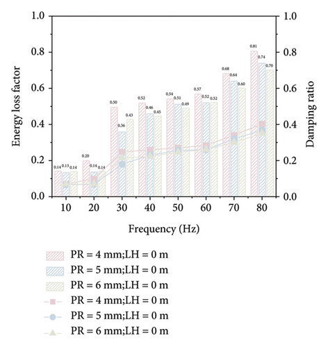
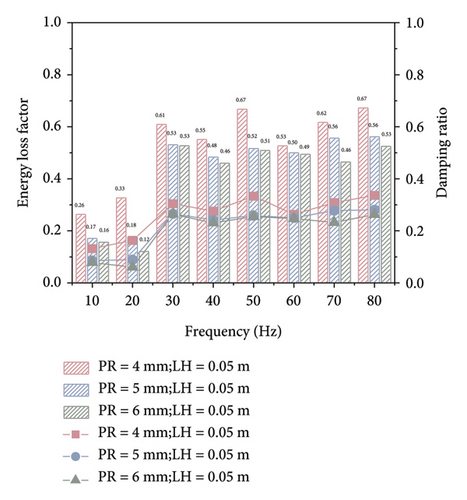
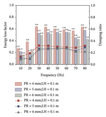
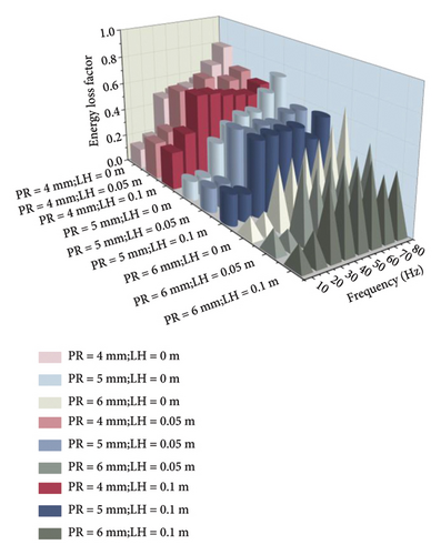
Figure 9(b) presents the energy loss factors of the TLPD system with PRs of 4, 5, and 6 mm when the LH is 0.05 m. The trend seen in the graph is generally consistent with that in Figure 9(a). However, the difference is that the energy loss factor and equivalent damping ratio of the TLPD system do not increase throughout the entire excitation frequency range but reach their maximum values around 50 Hz. It is noteworthy that, compared to case of no liquid, when the LH is 0.05 m, the maximum energy loss factor of the TLPD system at frequencies below 20 Hz can reach up to 0.33. This indicates that, relative to traditional PD systems, the TLPD system exhibits an enhanced vibration absorption capability at ultra-low frequencies.
Figure 9(c) presents the energy loss factors of the TLPD system with PRs of 4, 5, and 6 mm when the LH is 0.1 m. An interesting observation from the graph is that, compared to the TLPD system with a LH of 0.05 m, the TLPD system with a LH of 0.1 m can be regarded as a T-TLD system. The TLD system exhibits superior vibration absorption performance at ultra-low frequencies, reaching its maximum value of 0.64 around 30 Hz. However, beyond 30 Hz, as the excitation frequency increases, the energy loss factor of the TLD system gradually decreases, indicating a weakened vibration absorption capability compared to PD systems and TLPD systems.
Figure 9(d) provides a comparison of the nine computational scenarios to better highlight the influence of different PRs and LHs on the energy dissipation capability of the TLPD system. It is concluded that, when the LH is 0.05 m and the PR is 4 mm, the TLPD system exhibits optimal vibration absorption capability in the frequency range below 80 Hz. This conclusion will be further validated in the next section. Through parameter optimization analysis, we found that parameters such as PR, LH, and particle filling ratio have a significant impact on the vibration attenuation performance of TLPD-DVA. The optimization of these parameters not only enhances the damping efficiency of TLPD-DVA but also provides crucial design references for practical applications.
4. Harmonic Response Analysis of Steel-Spring FST With TLPD-DVAs
4.1. Harmonic Response Analysis Model
Harmonic response analysis is employed to investigate the steady-state response of a linear system under harmonic loading, providing the amplitude of displacement at different frequencies. By performing harmonic response analysis of the track before and after TLPD-DVA installation, the vibration characteristics of the track in the low-frequency range and the vibration suppression performance of the TLPD-DVA in the resonance region of the track can be compared. In this section, harmonic response analysis is conducted for different stiffness and damping values of the TLPD-DVA deviating from their optimal values. Harmonic response analysis is also performed for assessing the low-frequency vibration suppression performance of the TLPD-DVAs with different particle sizes.
To balance the accuracy and efficiency of the computational model, as shown in Figure 10, this study utilized the COMSOL Multiphysics software to establish a nine-span finite element model of a steel-spring FST with TLPD-DVAs. The TLPD-DVA, steel rails, floating slab, supporting layer, and foundation were all modeled using solid elements. To minimize the impact of elastic wave reflections on the calculation results, low-reflection boundary conditions were applied at the edges of the steel rails, floating slab, supporting layer, and foundation. Additionally, low-reflection boundary conditions were applied to the bottom and sides of the foundation, and the outermost nodes were fixed.
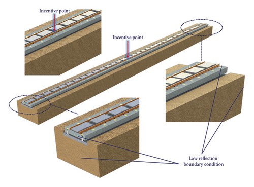
To account for the frequency-dependent damping effect of the TLPD-DVA, we added a damping ratio to the solid elements of the TLPD-DVA in the model. Specifically, the damping ratio values calculated under optimal grading in Section 3.3 were applied to the linear elastic material properties of the TLPD-DVA using interpolation. During the frequency-domain analysis, the simulation automatically utilized the frequency-dependent damping ratios from the interpolation table. The excitation force was applied at the highest point of the cross section of the steel rail at the midspan of the fifth span of the FST. The excitation force F was a harmonic unit force, with an analysis frequency range of 1 to 80 Hz and a frequency step of 0.1 Hz.
4.2. TLPD-DVA Performance Sensitivity to Parameter Changes
In Section 2.3, it was demonstrated that the optimal design of TLPD-DVA employed low stiffness and high damping. This enabled the dynamic absorber to suppress the low-frequency vibration peak of the FST by intensifying its own vibrations. This dissipates vibrational energy in the spring-damper connecting component and reduces the vibration of the FST. The stiffness and damping parameters of the connecting component directly impact the vibration suppression effectiveness of the dynamic absorber installed on the FST. In practical applications, due to various uncertainties, there may be deviations between the actual parameters of the absorber connecting component and the optimal design parameters. Therefore, it is necessary to analyze the influence of deviations in the absorber stiffness and damping from their optimal values on the low-frequency vibration suppression performance of the FST. Likewise, an analysis of the vibration damping effects of TLPD-DVA with different particle-liquid gradations on the FST system is essential to validate the optimal particle-liquid gradation.
In practical engineering applications, adjusting the damping and stiffness values obtained from theoretical optimization formulas to their optimal values requires comprehensive consideration of material properties, structural design, and actual working conditions. For the rubber layer in the TLPD-DVA system, parameters such as elastic modulus and damping characteristics directly affect the system’s stiffness and damping performance. These characteristics can be tuned to approach the theoretically optimized values by selecting appropriate rubber materials and adjusting their formulation. Similarly, in the TLPD system, parameters of the liquid and granular materials, such as density, viscosity, and particle size, also influence the system’s damping performance. Optimizing these parameters helps achieve the theoretical design objectives. Furthermore, the structural design parameters of the TLPD-DVA system—such as rubber layer thickness, liquid filling volume, and particle filling ratio—significantly impact the system’s stiffness and damping. These parameters can be adjusted according to the theoretical optimization targets to achieve optimal performance. For example, increasing the rubber layer thickness enhances system stiffness, while adjusting the liquid filling volume and particle filling ratio modifies the system’s damping characteristics. In practical applications, a multiobjective optimization approach is necessary to balance vibration control effectiveness, weight, cost, and other performance indicators. By integrating theoretical formulas with engineering constraints and validating the design through numerical simulations and experimental testing, the optimal design solution can be identified. Finally, experimental verification is an indispensable step, allowing for the evaluation of system performance and further refinement of the design based on test results to ensure the damping and stiffness values closely match the theoretical optimum.
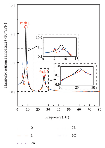
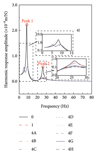
Table 4 presents the adopted computational scenarios. Scenario 0 denotes the case without DVAs, Scenario 1 corresponds to the optimal structural design parameters, Scenarios 2A to 2C represent cases with deviations in stiffness from the optimal value, Scenarios 3A to 3C are cases with deviations in damping from the optimal value, and Scenarios 4A to 4I represent cases with different particle-liquid gradation parameters.
| Working condition | Stiffness deviation (%) | Damping deviation (%) | Stiffness (kN/mm) | Damping (kN·s/m) |
|---|---|---|---|---|
| 1 | 0 | 0 | 9.5 | 98.5 |
| 2A | 0 | −25 | 9.5 | 73.875 |
| 2B | 0 | −50 | 9.5 | 49.25 |
| 2C | 0 | −75 | 9.5 | 24.625 |
| 3A | 25 | 0 | 11.875 | 98.5 |
| 3B | 50 | 0 | 14.25 | 98.5 |
| 3C | 75 | 0 | 16.625 | 98.5 |
| Working condition | Particle radius (mm) | Level height (m) | ||
| 4A | 4 | 0 | ||
| 4B | 4 | 0.05 | ||
| 4C | 4 | 0.1 | ||
| 4D | 5 | 0 | ||
| 4E | 5 | 0.05 | ||
| 4F | 5 | 0.1 | ||
| 4G | 6 | 0 | ||
| 4H | 6 | 0.05 | ||
| 3I | 6 | 0.1 | ||
The results of the computational scenarios listed in Table 4 are shown in Figure 11. From Figure 11(a), it can be observed that when the damping coefficient of TLPD-DVA deviates from its optimal value, the displacement of FST exhibits two distinct peaks in the frequency range of 5–10 Hz. These peaks are larger than those under the optimal damping condition but smaller than the displacement peaks without TLPD-DVA. Moreover, as the deviation in damping increases, i.e., as the damping parameter decreases, the peaks on both sides increase, indicating a decrease in the vibration control effectiveness of TLPD-DVA. When the damping coefficient of TLPD-DVA is at its optimal value, the displacement peaks of FST are 0.55 mm near 5 Hz, 0.57 mm near 10 Hz, and 0.31 mm near 30 Hz, respectively. In contrast, when the damping coefficient deviates from its optimal value by −75%, the displacement peaks of FST are significantly larger, reaching 1.00 mm near 5 Hz, 1.18 mm near 10 Hz, and 0.56 mm near 30 Hz, respectively.
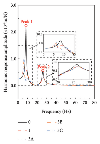
In Figure 11(b), it can be observed that when the stiffness of TLPD-DVA deviates by 75% from its optimal value, the FST displacement amplitude exhibits a peak at approximately 5–7 Hz. This corresponds to a reduction in the natural frequency of FST by 2-3 Hz. The peak is larger than the displacement peak under optimal parameter conditions but smaller than the displacement peak without TLPD-DVAs. Furthermore, as the stiffness deviation increases, i.e., as stiffness increases, the displacement peak also increases. In this frequency range, an amplification of FST displacement occurs. When the stiffness of TLPD-DVA deviates from its optimal value, the displacement peak of FST shifts to the left. However, in the frequency range of 8–13 Hz, the displacement amplitude of FST is smaller than that for the optimal stiffness, indicating an increase in the vibration suppression effectiveness of TLPD-DVAs. The displacement peak near 30 Hz is not significantly affected by the deviations in the stiffness of TLPD-DVA from the optimal value.
From Figure 11(c), it can be concluded that different TLPD-DVA particle-liquid gradations significantly affected the displacement amplitude of FST. The main reason is the variation in the equivalent damping ratio of TLPD at different gradations (refer to Figure 9(d)). It is evident that the equivalent damping ratio influences the displacement amplitude at various peak frequencies but does not affect these peak frequencies themselves.
4.3. Analysis of TLPD-DVA Vibration Reduction Mechanism
Figure 9 provides a macroscopic assessment of the damping performance exhibited by different particle-liquid gradations, showing the energy dissipation capability associated with each gradation. Figure 11(c) shows the harmonic response analysis results of the steel-spring FST vibration suppression performance of TLPD-DVAs. We will now further analyze the vibration reduction mechanism of TLPD-DVA from a microscopic perspective.
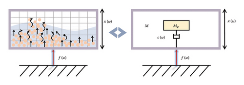
Equation (24) indicates that the effective dynamic mass corresponds to the mass of the granular liquid material directly involved in energy dissipation, without energy capture.
Postprocessing of the DEM-CFD particle-fluid two-phase flow simulation results yielded the average total kinetic energies and velocity amplitudes of the TLPD systems with different particle-liquid gradations. Using equations (27) and (28), relationships between the average kinetic energy and velocity amplitude of the TLPD system with different particle-liquid gradations in the frequency range of 10–80 Hz can be fitted. For detailed information, refer to Supporting Information S2 (Figures S2.1-S2.9).
Figure 13 illustrates the variation of effective dynamic mass and effective dynamic mass ratio with frequency for different particle-liquid configurations. As revealed by the velocity distribution of the TLPD system at various frequencies shown in Supporting Information S2, when the excitation frequency is very low, particles aggregate together and exhibit weak relative motions, and the entire particle assembly moves like a single entity, resulting in minimal energy dissipation. The effective dynamic mass of the particle group approaches its static mass. As the excitation frequency reaches a certain magnitude, the particle group enters a fully developed motion and collision state, achieving optimal damping effects, and the effective dynamic mass stabilizes at its minimum value. The simulation results from the DEM-CFD coupled model reveal that inelastic collisions and frictional effects between particles and liquid play a crucial role in energy dissipation within the low-frequency range. This interaction not only increases the system’s damping but also effectively converts vibration energy into thermal energy through particle motion and liquid sloshing responses. Compared to conventional DVAs, TLPD-DVA significantly enhances vibration attenuation in the ultra-low frequency range through this unique mechanism. To ensure a fair comparison, the absorbers used in subsequent experiments were designed to have the same mass, isolating the influence of mass increase from the observed vibration reduction effects. However, when the excitation frequency exceeds the optimal conditions, the limited movement space available the particles leads to a decrease in collision intensity and a reduction in energy dissipation. Compared to Figure 9, it can be observed that the effective dynamic mass follows a similar trend to the energy dissipation in the TLPD system, providing a microscopic perspective on the mechanism of its energy dissipation.
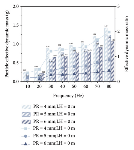
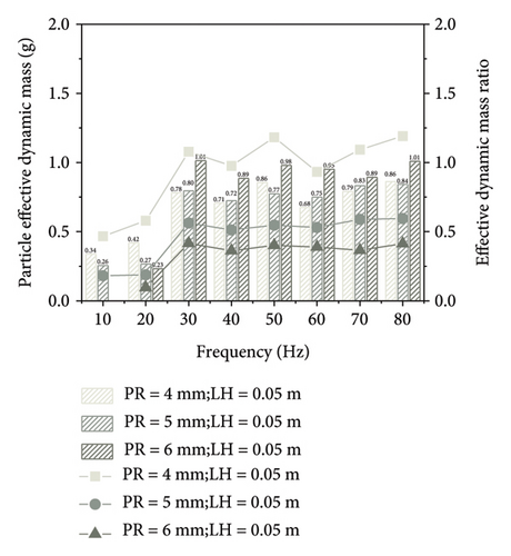
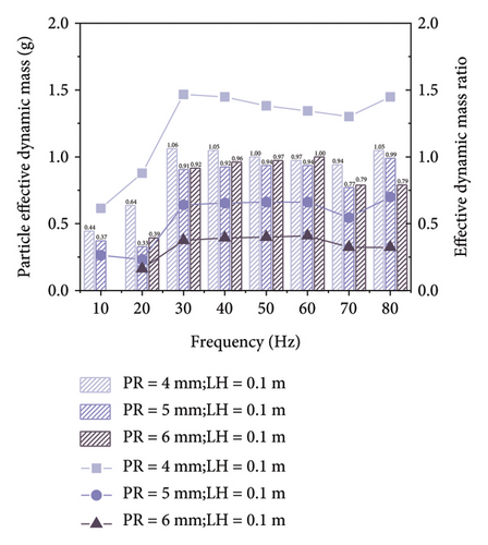
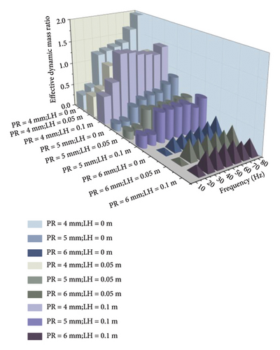
After conducting harmonic response analysis on the steel-spring FST equipped with TLPD-DVAs, the optimal particle-liquid configuration for the TLPD system can be determined. When the PR is 4 mm and the LH is 0.05 m, the TLPD-DVA exhibits the optimal vibration absorption performance. The subsequent dynamic simulation and experimental analyses will adopt this configuration.
5. Vibration Reduction Performance of TLPD-DVA Subjected to Dynamic Train Excitation
5.1. Dynamic Model of Vehicle-TLPD-DVA-FST-Tunnel System
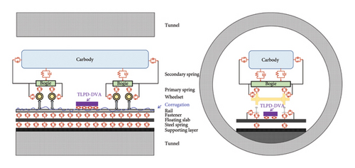
To effectively simulate the dynamic interactions between the subway vehicle and the FST with TLPD-DVA and evaluate its dynamic performance, a coupled dynamic model of vehicle-TLPD-DVA-FST-tunnel was established. As shown in Figure 14, the subway vehicle is considered as a multi-rigid-body system composed of the carbody, underframe, and wheelsets, considering lateral, vertical, roll, pitch, and yaw motions of each part. The subway vehicle is modeled as a six-car trainset of type A, where each car consists of a carbody, two bogies, four wheelsets (LMA type tread), and eight axle boxes. The carbody and bogies have three translational and three rotational DOFs, while the wheelsets have two translational DOFs (lateral translation is achieved by specifying the travel speed) and three rotational DOFs. The wheel-rail contact is modeled using a series of springs and dampers connecting the wheels to the axle boxes and the bogies to the carbody. The parameters of the subway vehicle are provided in Table 5.
| Item | Notation | Value | Unit |
|---|---|---|---|
| Car body mass | Mc | 41.8 | t |
| Mass moment of inertia of car body roll | Icx | 155 | t |
| Mass moment of inertia of car body pitch | Icy | 1959 | t·m2 |
| Mass moment of inertia of car body yaw | Icz | 1875 | t·m2 |
| Mass of bogie | Mb | 7.36 | t |
| Mass moment of inertia of bogie roll | Itx | 5.07 | t·m2 |
| Mass moment of inertia of bogie pitch | Ity | 1.47 | t·m2 |
| Mass moment of inertia of bogie yaw | Itz | 3.43 | t·m2 |
| Mass of wheelset | Mw | 1.78 | t |
| Mass moment of inertia of wheelset roll | Iwx | 0.92 | t·m2 |
| Mass moment of inertia of wheelset pitch | Iwy | 0.3 | t·m2 |
| Mass moment of inertia of wheelset yaw | Iwz | 0.92 | t·m2 |
| Longitudinal stiffness of secondary suspension system | Ksx | 194 | kN/m |
| Lateral stiffness of secondary suspension system | Ksy | 194 | kN/m |
| Vertical stiffness of secondary suspension system | Ksz | 200 | kN/m |
| Longitudinal damping of secondary suspension system | Csx | 50 | kN·s/m |
| Lateral damping of secondary suspension system | Csx | 50 | kN·s/m |
| Vertical damping of secondary suspension system | Csz | 80 | kN·s/m |
| Longitudinal stiffness of primary suspension system | Kpx | 332 | kN/m |
| Lateral stiffness of primary suspension system | Kpy | 332 | kN/m |
| Vertical stiffness of primary suspension system | Kpz | 900 | kN/m |
| Longitudinal damping of secondary suspension system | Cpx | 2 | kN·s/m |
| Lateral damping of primary suspension system | Cpy | 2 | kN·s/m |
| Vertical damping of primary suspension system | Cpz | 5 | kN·s/m |
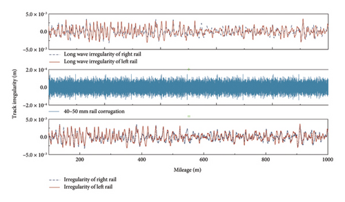
The rail is modeled using the Timoshenko beam, while the TLPD-DVA, floating slab, and tunnel structure are simulated using solid elements, interconnected through steel springs (3-DOF spring-damper units). The connection between the rail and the floating slab is achieved using fasteners (6-DOF spring-damper units), while the tunnel walls are fixed using linear force elements. The longitudinal spacing of the fasteners is 0.6 m and the lateral spacing is 1.5 m. The longitudinal spacing of the steel springs is 1.2 m and the lateral spacing is 1.5 m. Two floating slabs are connected with shear hinges (high-stiffness 3-DOF springs units) to ensure consistent displacements at the slab ends. The parameters of the FST and tunnel are provided in Table 1. To minimize the impact of variations in track structure stiffness and boundary effects on the computational results, a model of six 9 m-long floating slabs is established, with adjacent slabs connected by five shear hinges. As shown in Figure 15, the track irregularities were modeled based on measured data, which include short-wave rail corrugation with a wavelength of 40–50 mm and a wave depth ranging from 0.05 to 0.25 mm, and the typical measured long-wave rail irregularity was superposed. The normal forces between the wheel and rail are determined using the Hertzian nonlinear elastic contact theory, while the tangential forces using the creep theory. The transient dynamic analysis employed the modal superposition method, which facilitates the inclusion of mode-specific damping ratios. To linearize the nonlinear damping characteristics of the TLPD, the equivalent damping ratio was expressed as a function of the structural mode shapes. This linearized damping was then implemented using a linear interpolation table, correlating the damping ratio with the corresponding mode shape of the TLPD-DVA structure. This approach effectively integrated the damping effect into the solid elements of the TLPD-DVA within the framework of the modal analysis.
5.2. Dynamic Response Analysis
To investigate the vibration reduction performance of TLPD-DVA under the action of train loads, dynamic response analyses were conducted for the coupled system of FST and tunnel under three conditions: with additional TLPD-DVAs, with additional T-DVAs, and without DVAs. The subway train speed was in all cases 60 km/h.
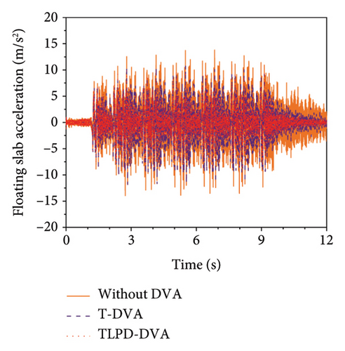
Figure 16 illustrates the time history comparison of vertical accelerations and displacements of the floating slab under the action of train loads for the three scenarios. Interestingly, the vertical accelerations of the floating slab were significantly lower when TLPD-DVAs were added compared to the scenarios with additional T-DVA and without DVA. Specifically, compared to the no-DVA case, the T-DVA reduced the peak and RMS acceleration values by 21.95% and 21.39%, respectively, while the TLPD-DVA achieved reductions of 28.53% and 39.78%. Moreover, the TLPD-DVA also outperformed the T-DVA, providing an additional reduction of 6.58% in peak acceleration and 18.39% in RMS acceleration. These quantitative results are summarized in Table 6, which clearly highlights the superior broadband vibration reduction capability of the proposed TLPD-DVA. However, the differences in vertical displacements among these three conditions are not significant. The observed differences between acceleration and displacement responses arise from the inherent characteristics of these two types of measurements. Mathematically, acceleration and displacement responses are linked through the frequency content of the excitation signal. Acceleration is more sensitive to higher frequency components, which usually have a more pronounced effect on it, while lower frequency components predominantly influence displacement. Therefore, the significant differences between the acceleration and displacement responses in Figure 16 can be attributed to the distribution of excitation frequencies and the dynamic properties of the system.
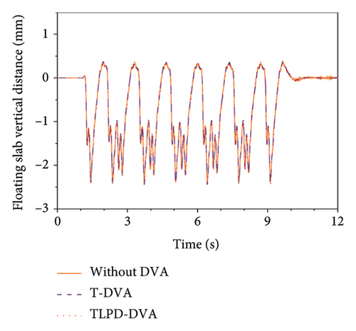
| Working condition | Peak acceleration (m/s2) | Peak reduction (%) | RMS acceleration (m/s2) | RMS reduction (%) |
|---|---|---|---|---|
| Without DVA | 3.45 | — | 0.85 | — |
| With T-DVA | 2.69 | 21.95% | 0.67 | 21.39% |
| With TLPD-DVA | 2.47 | 28.53% | 0.51 | 39.78% |
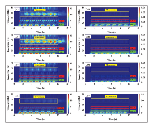
Figures 17(a1)-(a3) present the time-frequency plots of vertical accelerations at the midspan of the third floating slab under the action of train loads with the additional TLPD-DVAs, additional T-DVAs, and without DVAs, respectively. The horizontal axis is time and the vertical axis is frequency, while colors represent the amplitude of acceleration in time and frequency, measured in (m/s2). In the frequency range labeled as Peak 1, prominent bright spots are observed below 10 Hz, indicating intense vibrations in this frequency range. This agrees with the results presented in Section 4.2, where 10 Hz corresponded to a major resonance frequency of the vertical vibration of the FST system. When the TLPD-DVAs were added, a significant reduction in vibration acceleration amplitude is evident in this frequency range compared to the case without DVAs, whereas the reduction with T-DVAs is not as pronounced. In the frequency range labeled as Peak 2, bright spots around 30 Hz are caused by the bending vibration of the FST system. The addition of TLPD-DVAs shows a remarkable damping effect in the 30 Hz frequency range compared to T-DVAs. The bright spot around 50 Hz is related to the resonance between the spring mass and the track mass, known as P2 resonance. It is mainly influenced by the spring mass, fastener stiffness, and track sleeper spacing. It can be observed that the addition of T-DVAs slightly increases the vibration response in this frequency range, which can be attributed to the increased overall mass of the track system due to the additional T-DVAs. However, the TLPD-DVAs significantly reduce the amplitude in this frequency range, mainly due to its high damping ratio, effectively suppressing this resonance.
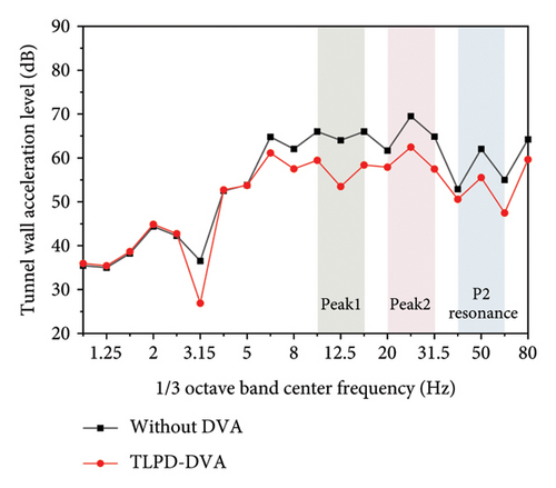
To further quantitatively investigate the vibration reduction performance of TLPD-DVAs for the FST system under train loading, Figure 18 presents the one-third octave band center frequency spectrum of vertical acceleration levels at the midspan of the third floating slab and the corresponding tunnel wall position for the cases with attached TLPD-DVAs, attached T-DVAs, and without DVAs. From the figure, it is evident that in the Peak 1, Peak 2, and P2 resonance frequency ranges, the TLPD-DVAs provide good vibration reduction, consistent with the design frequency bands.
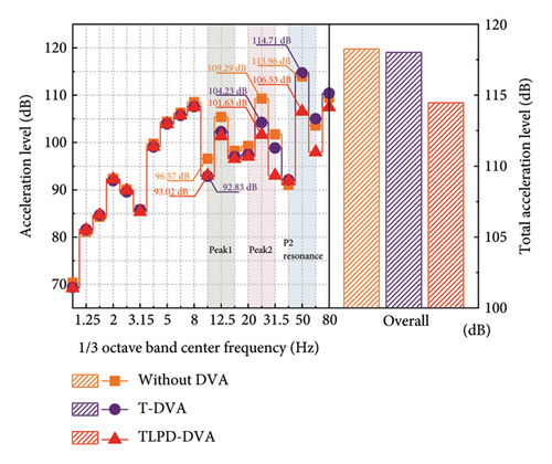
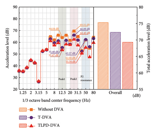
In Figure 18(a), the TLPD-DVAs demonstrate a broader frequency band of vibration reduction compared to the T-DVAs with a superior vibration reduction performance. The TLPD-DVAs can reduce the floating slab vibration by approximately 4 dB compared to the case without DVAs, while T-DVAs reduce it by only about 1 dB. It should be noted that the observed reduction effect mainly occurs at frequencies above 10 Hz. This is not due to an inherent limitation of the TLPD itself, but rather results from the dynamic characteristics of the FST system, whose first vertical vibration mode occurs around 10 Hz (as shown in Figure 3). In structural systems with lower modal frequencies—such as buildings or bridges—the TLPD can be designed to operate effectively at lower frequency ranges. Figure 18(b) illustrates that the vibration reduction band of TLPD-DVAs for the tunnel wall is generally consistent with that of the floating slab, and their effect is also superior to T-DVAs. Below 80 Hz, the TLPD-DVAs reduce the tunnel wall vibration by approximately 5 dB compared to the case without DVAs, while T-DVAs reduce it by about 3 dB.
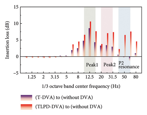
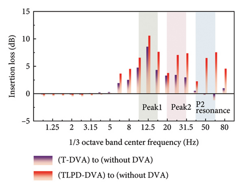
From Figure 19(a), a more intuitive understanding of the wideband reduction effects of the two types of dynamic absorbers on the floating slab vibrations can be obtained. It also illustrates the role of the TLPD mechanism. In the vicinity of Peak 1, the vibration reduction effect of TLPD-DVAs can reach 4 dB, an improvement of 1 dB compared to T-DVAs. In Peak 2 frequency range, TLPD-DVA vibration reduction effect can reach 8 dB, an improvement of 4 dB compared to T-DVA. At the same time, for the P2 resonance frequency range, the TLPD-DVAs completely overcome the disadvantage of T-DVAs and exhibit outstanding vibration reduction performance in this frequency range. Figure 19(b) is similar to 19(a). Both types of dynamic absorbers achieved a wideband reduction effect on the tunnel wall vibrations. In the Peak 1 frequency range, the vibration reduction effect of TLPD-DVAs can reach 10 dB, an improvement of 2 dB compared to T-DVAs. In the Peak 2 frequency range, the TLPD-DVA vibration reduction effect can reach 7 dB, an improvement of 4 dB compared to T-DVAs. Meanwhile, for the P2 resonance frequency range, the TLPD-DVA vibration reduction effect can reach 7 dB.
By establishing a coupled vehicle-TLPD-DVA-FST-tunnel dynamic model, this study conducts a detailed analysis of the vibration absorption characteristics of the TLPD-DVA under train dynamic loads. Simulation results indicate that the TLPD-DVA exhibits significant vibration attenuation in the ultra-low-frequency range compared to conventional DVAs. These findings not only provide theoretical support for the design of the TLPD-DVA but also serve as a critical reference for subsequent experimental validation.
6. Experimental Validation of Steel-Spring FST With TLPD-DVAs
6.1. Experimental Plan
To measure the actual vibration reduction effect of a TLPD-DVA applied to a steel-spring FST system, a physical prototype of the dynamic absorber was created and implemented on an urban rail transit line as shown in Figure 20(a). The vibration reduction in the steel-spring FST after the application of TLPD-DVAs was tested. The primary material parameters for each component used in the production of the TLPD-DVA are listed in Table 2. However, due to practical manufacturing variations, there may be minor deviations between the structural parameters achieved with these material values and the optimal values determined through simulations. The test section was selected on a straight track with good construction quality and DT-III2 type fasteners. The train speed was between 55 and 65 km/h. Additionally, the test section was free of standing water. The length of the test area was not less than 150 m.
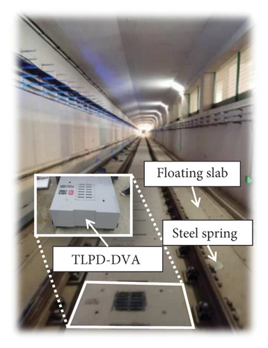
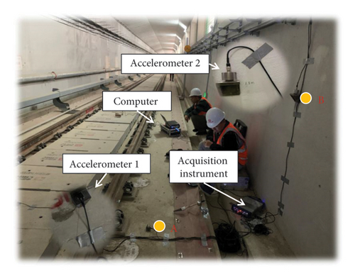
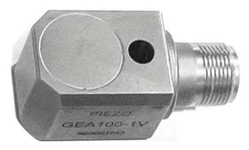
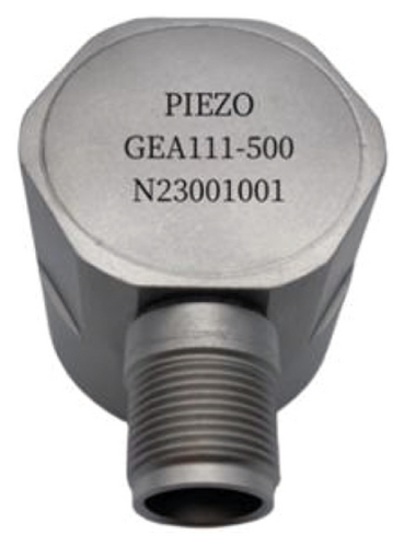
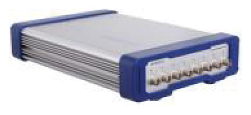
Figure 20 shows the layout of measurement points at the test section during on-site testing. Acceleration sensors were positioned vertically on the TLPD-DVA, the floating slab, and the tunnel wall. Accelerations were measured when a subway train passed through the test section. In Figure 20(b), measurement point A was located above the floating slab, 0.8 m away from the track centerline, and measurement point B was positioned 1.25 m above the tunnel wall. The main instruments used in this test were the INV3062C 8-channel data acquisition system developed by the China Orient Institute of Noise & Vibration and the ICP acceleration sensors GEA100-500 and GEA111-500 developed by Chengdu Peria Sensor Technology Co. Ltd. shown in Figures 20(c), 20(d), and 20(e). Both sensors were set up for offline monitoring. The GEA100-500 accelerometer has a sensitivity of 10 mV/(m/s2) and an effective frequency range from 0.2 Hz to 15 kHz, while the GEA111-500 accelerometer has a sensitivity of 1 mV/(m/s2) and an effective frequency range from 0.2 Hz to 15 kHz. The INV3018CT data acquisition system can achieve a maximum sampling frequency of 100 kHz per channel. The sampling frequency was set at 5120 Hz and each recording lasted at least 30 s, i.e., enough to capture the entire train passage through the test section.
6.2. Analysis of Experimental Results
Figure 21 presents the test results at measurement point A before and after the installation of the TLPD-DVA. By analyzing the distribution patterns of the floating slab’s vibration acceleration in the time-frequency domain from 20 sets of data, Figure 21(a) shows a comparison of a typical time-domain dataset at measurement point A before and after applying the TLPD-DVA, while Figure 21(b) provides a frequency spectrum comparison for this typical time-domain data. Figure 21(c) presents a comparison of the frequency-domain analysis results for 20 sets of field measurements and simulation data, and Figure 21(d) compares the 1/3 octave band results at measurement point A before and after the TLPD-DVA installation. From Figure 21(a), it can be observed that although there is a slight reduction in the vibration acceleration of the floating slab after the installation of the TLPD-DVA, the difference is not prominent when observed solely in the time domain. Therefore, further frequency-domain analysis is required for a more accurate assessment. Figure 21(b) presents the frequency-domain analysis results, showing that after installing the TLPD-DVA, the vibration acceleration of the floating slab significantly decreases in the 20–80 Hz frequency range. Figure 21(c) compares the numerical and experimental results before and after the TLPD-DVA installation, revealing some discrepancies between the numerical and experimental results in certain frequency ranges, though the overall consistency is relatively high. These differences are mainly attributed to unstable train speeds during testing. Figure 21(d) further illustrates the reduction in vibration acceleration at measurement point A, where the TLPD-DVA shows effective vibration reduction in the Peak 1, Peak 2, and P2 resonance frequency ranges, corresponding to the design frequency bands.
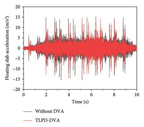
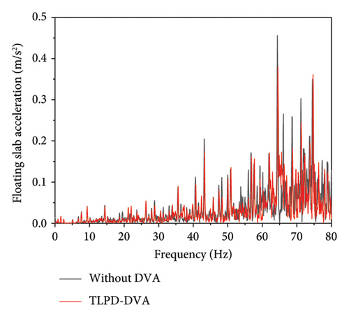
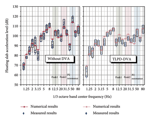
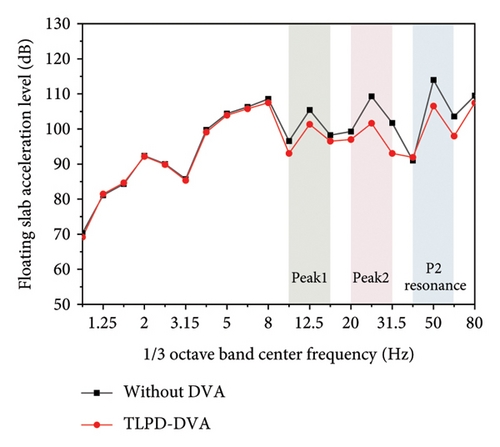
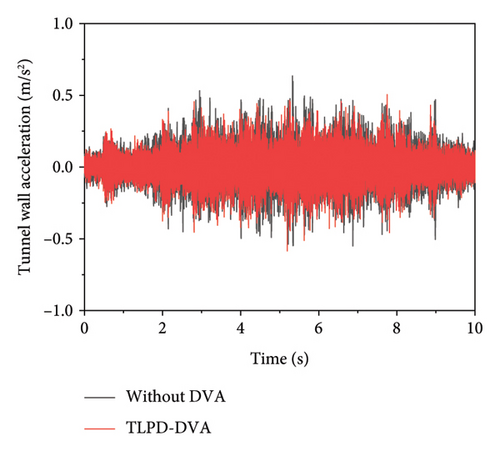
Figure 22 presents the test results at measurement point B before and after the installation of the TLPD-DVA. By analyzing the distribution patterns of the tunnel wall’s vibration acceleration in the time-frequency domain from 20 sets of test data, Figure 22(a) shows a comparison of a typical time-domain dataset at measurement point B before and after applying the TLPD-DVA, while Figure 22(b) provides a frequency spectrum comparison for this typical time-domain data. Figure 22(c) presents a comparison of the frequency-domain analysis results for 20 sets of field measurements and simulation data, and Figure 22(d) compares the 1/3 octave band results at measurement point B before and after the TLPD-DVA installation. It can be observed and analyzed that after the installation of the TLPD-DVA, there is a certain degree of reduction in the vibration acceleration of the tunnel wall. Further frequency-domain analysis reveals that the TLPD-DVA effectively reduces vibrations within the design frequency range, with good agreement between the test and numerical results.
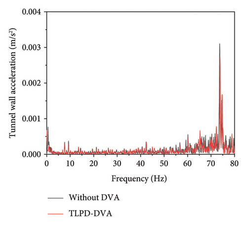
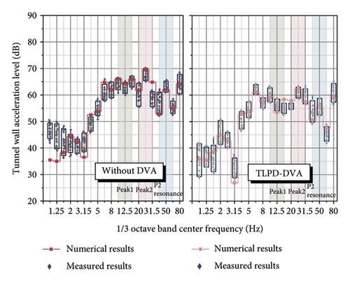
To assess the vibration attenuation performance of the TLPD-DVA in practical applications, full-scale experiments were conducted. The results demonstrate that the TLPD-DVA significantly reduces the vibration acceleration of the FST in the ultra-low-frequency range, showing good agreement with the theoretical simulations. These experimental findings not only validate the accuracy of the theoretical model but also provide solid support for the practical implementation of the TLPD-DVA. However, certain discrepancies were observed between the experimental results and theoretical predictions during the field tests. These differences are primarily attributed to complex real-world factors such as variations in train operating speed, track irregularities, and particle material wear. While these factors are difficult to fully capture in theoretical models, our comparative analysis of the experimental data allows for a better understanding of their influence on TLPD-DVA performance and provides valuable insights for further improvements in future research.
7. Conclusions
- 1.
The multi-DOF system equivalent mass identification method and the fixed-point theory were employed. Based on the parameters of a short steel-spring FST and modal analysis of the FST, the optimal parameters for the floating slab vibration absorber were found, providing important information for the practical application of the TLPD-DVA. This approach offers a novel solution for real-world implementation of FST systems, providing a pathway to optimize the design and integration of passive vibration absorbers in infrastructure projects.
- 2.
Using the DEM-CFD gas-liquid-particle multiphase flow simulation model, the system parameters of the TLPD-DVA were optimized to design a variable-frequency nonlinear TLPD-DVA device. The harmonic response analysis of the steel-spring FST system with TLPD-DVAs was conducted using performance indicators, such as effective dynamic mass and effective dynamic mass ratio, to explore the vibration reduction mechanism of TLPD-DVA at a deeper level. The results revealed that the TLPD-DVA exhibits superior vibration attenuation properties, particularly in the low-frequency range, highlighting its potential for large-scale structural applications in transport systems.
- 3.
A coupled vehicle-TLPD-DVA-FST-tunnel dynamic analytical model was established to analyze the dynamic vibration absorption characteristics of TLPD-DVA under dynamic train loads. It was found that the TLPD-DVAs reduced the maximum vertical acceleration level of the floating slab by up to 8 dB and the tunnel wall acceleration level by up to 10 dB compared to the T-DVAs. This demonstrates the enhanced effectiveness of the TLPD-DVA in real-world operational conditions, providing tangible improvements in structural performance and comfort.
- 4.
Finally, experiments on the developed TLPD-DVA were conducted to further validate the reliability and dynamic performance of TLPD-DVA under low-frequency vibrations. The experimental validation supports the feasibility of implementing TLPD-DVA in urban rail transit systems, ensuring its robustness and practical applicability in mitigating low-frequency vibrations in various operational environments.
In summary, the proposed TLPD-DVA is a promising integrated passive vibration absorber that is expected to effectively address the issue of low-frequency vibrations in FST systems. Its design and development have undergone multiple verification stages, including theoretical simulations, experimental studies, parameter optimization, and on-site testing. It provides an effective solution ensuring the stability and safety of FST systems, holding significant promise for the vibration reduction in track structures in future urban rail transit systems. Future research will focus on optimizing the TLPD-DVA for even more complex environments, incorporating advanced materials and adaptive control technologies to further enhance its efficiency. Moreover, since the geometry of the TLPD cavity may influence the internal flow patterns, collision dynamics, and energy dissipation performance of the particle-liquid mixture, future work will also include a systematic parametric study to investigate how variations in cavity dimensions—such as aspect ratio and liquid depth—affect the damping behavior of the TLPD-DVA. This will support the development of more adaptable and performance-optimized damper configurations for engineering practice.
Conflicts of Interest
The authors declare no conflicts of interest.
Author Contributions
Duojia Shi: conceptualization, methodology, investigation, software, writing–original draft, and writing–review and editing. Pengzhan Liu: conceptualization, writing–review and editing, supervision, and funding acquisition. Tao Lu: conceptualization, methodology, validation, writing–review and editing, and supervision. Yi Qiu: data curation, investigation, and supervision. Linlin Xie: investigation and supervision. Bingfeng Ng: conceptualization, investigation, writing–review and editing, and supervision. Caiyou Zhao: data curation, visualization, and investigation. Ping Wang: formal analysis and validation.
Funding
This study was supported by the National Natural Science Foundation of China, 51978585 and 52108420, National Key Research and Development Program of China, 2022YFB2603404, High-Speed Rail Joint Fund Key Projects of Basic Research, U1734207, and Scientific Research Fund of Multi-Functional Shaking Tables Laboratory of Beijing University of Civil Engineering and Architecture, 2023MFSTL12.
Acknowledgments
This work was supported by the grants from the National Natural Science Foundation of China (grant numbers 51978585 and 52108420), National Key Research and Development Program of China (grant number 2022YFB2603404), High-Speed Rail Joint Fund Key Projects of Basic Research (grant number U1734207), and Scientific Research Fund of Multi-Functional Shaking Tables Laboratory of Beijing University of Civil Engineering and Architecture (grant number 2023MFSTL12).
Supporting Information
The Supporting Information provides detailed information on the computational framework and analysis supporting the findings in this study.
S1 section outlines the iterative computational process in the DEM-CFD model.
S2 section presents the postprocessing results of the DEM-CFD simulations, highlighting the relationships between average kinetic energy and velocity amplitude of the TLPD system across different particle-liquid gradations.
Open Research
Data Availability Statement
The data that support the findings of this study are available in the supporting information of this article.


