Dynamic Vibration Characteristics and Mitigation of the Stress-Ribbon Bridge by Using a Rail-Damper System
Abstract
Due to its simple and beautiful architectural appearance, the stress-ribbon bridge (SRB) has been gradually built around the world as a pedestrian or traffic bridge. However, as characterized by low bending stiffness and low damping ratio features, SRB is prone to the dynamic effects of external excitations, such as pedestrians, vehicles, and/or winds. To control the vertical vibration of the SRB, a rail-damper system is proposed in this study. In the proposed scheme, the rotation of the handrails triggered by the flexural deformation of the SRB is utilized to drive the viscous dampers installed between the adjacent handrails. The governing equations of the proposed control system are established. The key design parameters and their influences on the dynamic properties of the control system are systematically investigated. The control performances of the proposed rail-damper system are further investigated through an SRB numerical model subjected to pedestrian excitations. It is discovered that the rail-damper system can offer considerable supplemental damping to the structural modes through reasonable design, achieving satisfactory control performances. To gain the excellent effect of the proposed rail-damper system in real applications, a nondimensional rail stiffness of no less than 1000 is recommended, and the stiffness of the damper should be controlled as small as possible.
1. Introduction
Among the different structural forms of bridges, the stress-ribbon bridge (SRB) is considered as the most elegant one due to its simple form and beautiful architectural appearance [1]. The SRB is developed from the ancient suspension bridge, in which, the prestressed steel ribbons (or steel bands) are anchored at the abutments on both sides and are covered by the precast concrete slabs. The concept of modern SRB was first proposed as an architectural scheme passing across the Bosporus [2].The first SRB, the Leonel Viera Bridge, was built in 1965 [3]. After that, several SRBs have been built all over the world as pedestrian or traffic bridges, such as the Karlssteg Bridge [4], the IGA North Bridge [5], and the Pedro Gómez Bosque Bridge [6]. Recently, with the help of lightweight and high-strength materials (e.g., carbon fiber ribbons), SRBs with larger spanning capacities have been studied by scholars and bridge engineers [7].
However, SRB is characterized by low bending stiffness and low damping ratio. Thus, it is highly sensitive to the external excitations, such as pedestrians [8] or winds [9]. The unfavorable vibrations can trigger discomfort and panic among the bridge users or even cause damage to the structure, threatening the serviceability and safety of the SRB. Therefore, effective control of the unfavorable vibrations of the SRB is a vital issue for its design, construction, and applications.
In terms of vibration control of the bridges, there are generally two strategies [10–12], namely, (a) modifying the bridge’s natural frequencies to prevent resonance with external excitation frequencies (b) or increasing the bridge’s damping through supplemental damping devices. However, shifting the bridge’s frequency requires a great modification of the geometrical size of the deck as well as the axis force of the ribbons (i.e., increasing the geometric stiffness). In contrast, applying extra devices seems to be more preferable for the vibration control of the SRB.
Among the supplemental devices, a tuned mass damper (TMD) is one of the most commonly used structural control techniques [13, 14]. Moutinho et al. [15] reported the work for suppressing the vibration of a SRB in the FEUP campus via TMD. In this case, a single TMD could not act efficiently on the untargeted vibration modes. Thus, a semiactive TMD was adopted, and a much better control efficiency was achieved. Soria et al. [6] compared different control strategies for suppressing the pedestrian-induced vibrations of the SRB. It showed that the TMD’s efficiency degrades significantly when the bridge’s modal frequency moves away from the nominal model, based on which the TMD was designed. In comparison, the semiactive and active TMDs are less sensitive to the variation of modal frequencies. In addition, researchers also proposed different types of TMDs for vibration control of SRBs, such as the eddy-current TMD [7] and the rolling-ball TMD [9]. As a matter of fact, the TMDs are widely used in controlling the vibration of bridges (not just limited to the SRB emphasized in this paper). Huang et al. [16] proposed to combine TMD with bending shape memory alloy to mitigate the excessive vibration caused by pedestrians. Shi et al. [17, 18] developed the self-adjustable variable mass TMD (SAVM-TMD) and adaptive–passive variable mass TMD (APVMS-TMD) to control the vibration of the bridge. Bortoluzzi et al. [19] appended the TMD directly to the middle point of the tubular steel stays to mitigate wind-induced local vibrations of a timber footbridge. Wang et al. [20, 21] further developed variable mass/stiffness TMDs and applied them in controlling the human-induced vibration of long-span floor slabs as well as slender bridges. However, the deck plate of the SRB is quite thin; thus, the TMDs can hardly be installed inside the deck plate but have to be hanged at the bottom of the deck. This layout can obviously influence the architectural aesthetics of the SRB. Moreover, the large mass ratio required by the TMD to achieve better performance also contradicts the lightweight demand of SRB [22].
As an alternative potential approach, Bleicher et al. [23] introduced active control forces to the SRB at the handrail level via a pair of pneumatic muscle actuators (PMAs) which are placed horizontally between the handrails. A 13-m SRB with CFRP ribbons in the Berlin Institute of Technology was adopted to verify the efficiency of the proposed method. Later, Jirasek, Schauer, and Bleicher [24] extended the control systems to suppress the first torsional mode of the same bridge. The active PMAs are quite lightweight compared to the TMDs. Besides, they can achieve a better control efficiency at low-amplitude excitations as well as a better robustness versus variations in structural dynamic properties. However, as an active control strategy, it requires external energy input and involves control stability and robustness problems. On the other hand, the cost of maintenance could also be quite high.
The high efficiency of the PMAs at low-amplitude excitation, to a certain extent, relies on the force-amplification mechanism of the rail–slab system. This mechanism is similar to the concept of the damped-outrigger originating from response suppression of high-rise buildings [25–27], that is, the small-amplitude rotation of the deck plate during vertical deformation can be transferred to the relatively large-amplitude horizontal movement of the rail-end. This mechanism works like amplifying the relative deformation of the deck plate, or in another word, amplifying the force effect of the PMA imposed on the bridge. Quite recently, the outrigger-damping concept has also been introduced to the vibration control of bridges. Nagarajaiah, Chen, and Wang [28] proposed to use the negative stiffness and inerter system with damped-outrigger for seismic and wind response reduction of bridges and buildings. Chen et al. [29] introduced a damped-outrigger to the suspension bridge by installing it between the bridge girder and the tower for suppressing the vortex-induced vibration (VIV) of the bridge. Xiao et al. [30] proposed to use the damped-outrigger with negative stiffness elements to generate band gaps and to form the metamaterial beams. In addition, Wang et al. [31] transferred the higher part rotation of the wind turbine to its bottom with damping amplification and validated its efficiency through the shaking table test [32]. However, in the above studies, the host structures were assumed to be beam-like structures dominated by their bending stiffness, whereas the SRB is characterized by the axis forces (i.e., the geometric stiffness). The conclusions in the above studies cannot be directly adopted to guide the vibration control of the SRB.
In this study, a rail-damper system is proposed for vibration control of the SRB. In particular, the geometric stiffness of the SRB is considered and the influence of dynamic property change of the SRB is evaluated and investigated. The organization of this paper is as follows. In Section 2, the governing equations of the SRB with rail dampers are established. In Section 3, the key design parameters and their influences on the dynamic properties of the control system are investigated. In Section 4, the vibration control performance of the proposed rail-damper system is further investigated through an SRB numerical model subjected to pedestrian excitations. In Section 5, the concluding remarks of this study are drawn.
2. Modeling of the Control System
Figure 1 presents the schematic diagram of the SRB with the proposed rail-damper system. The SRB with a span length of L consists of a stress ribbon anchored at the abutments on both sides, with the pretension force of P in the X-axis (horizontal direction along the bridge). The stressed ribbon is then covered by the precast concrete slabs with periodically cantilevered rails. The proposed rail-damper system installs a passive damper between the handrails of the SRB with a spanning length of l. When the SRB exhibits the vibration in the Y-axis (e.g., vertical direction perpendicular to the bridge), the flexural deformation of SRB (or rotation) will trigger the handrail to deform in the X-axis, compressing/tensioning the dampers installed in adjacent handrails. In this way, extra energy dissipation capability shall be provided to the SRB. As shown in Figure 1(b), the analytical model of the rail-damper system can be further simplified, where the spring element kri represents the stiffness of the handrail, and the elements kdi and cdi represent the stiffness and damping of the damper, respectively. In that case, the proposed rail-damper model can degrade to the Maxwell or Kelvin model to reflect the complexity of actual dampers, or degrade to the dashpot model to simulate the ideal damper.
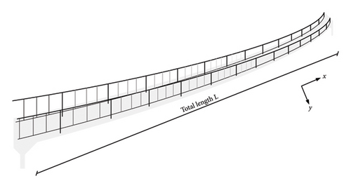
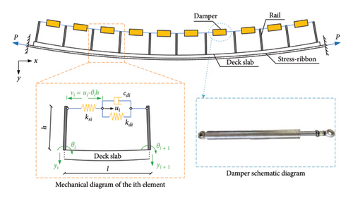
During the construction, the ribbons of the SRB are normally pretensioned and then the concrete deck slabs are covered. After that, the SRB gets its completion-state deformation shape, and the ribbons get the final tensioning force. When the external forces are imposed on the SRB, the SRB will further deform from the completion-state shape, and the tensioning forces of the ribbons will be changed. However, due to the gravity stiffness effect, the vibration amplitude of the SRB is relatively small compared with its geometrical size. To simplify the process of analysis, the variation in the tensioning force P is ignored in the following analysis.
2.1. Governing Equations of Motion
The matrices and denote the damping and stiffness effects of the rail dampers imposed on the SRB. is a diagonal matrix related to the dampers. are the nondiagonal terms, in which, [φ] is a location matrix that considers the different installation positions of the dampers along the bridge. is a diagonal matrix related to the stiffness effects of the dampers and the handrails. are the nondiagonal terms in the stiffness matrix.
2.2. Key Design Parameters
According to the governing equations, the dynamic properties of the control system depend on both the parameters of the rail-damper system and the structural system. The key design parameters for the rail-damper system include the damping coefficients (cdi), the stiffness of the damper (kdi), the height of the rail (h), and the stiffness of the handrail (kri). The key structural parameters include the bending stiffness of the SRB (EI), the tensioning force of the ribbons (P), the mass of the SRB (m), and the length of the SRB (L).
3. Multimode Damping Effect of the Rail-Damper System
3.1. Influence of Geometric Stiffness
The ratio between the geometric stiffness and bending stiffness (i.e., β) is the main design parameter for the SRB. When the value of β is small, the SRB behaves more like a beam. In contrast, it is more like a cable. Previous studies on SRBs reported that the value of β is normally within the range of 15–30 [1, 34]. Therefore, a variation range of 10–40 is adopted for investigating its influence. To reduce the calculation amount, ten dampers are installed along the SRB. For each damper, the spanning distance takes l/L = 1/10.
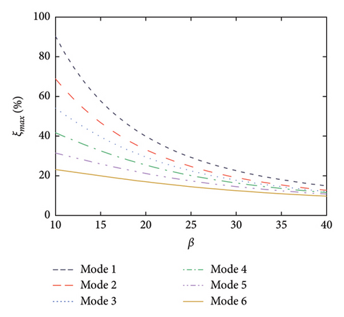
Figure 2 shows the supplemental damping ratios to the first six modes of the SRB by the rail-damper system at different values of nondimensional damping coefficients (φ) and nondimensional geometric stiffness (β). As can be seen, with the increment of the damping coefficient, the supplemental damping ratios increase gradually from the beginning and then decrease after an extreme point is reached. This phenomenon indicates that there exists an optimal value for the nondimensional damping coefficient. Taking Mode 1 as an illustration, the optimal damping coefficient is φopt = 15.48. As for the influence of geometric stiffness, an increment in this value will lead to a decrease in the supplemental modal damping ratios. In addition, the maximum supplemental damping ratio as well as the corresponding value of φopt will decrease with the increment of the mode number. This phenomenon may be due to the frequency-dependent feature of viscous dampers [35], that is, for the same damping coefficient, a higher modal frequency naturally leads to a lower value of modal damping ratio. However, it should be noted that even for the worst condition (e.g., Mode 6 with β = 35), the maximum supplemental damping ratio could still be 10%. Besides, the optimal value of the nondimensional damping coefficient is insensitive to the geometric stiffness.
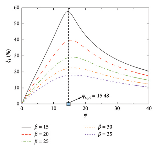
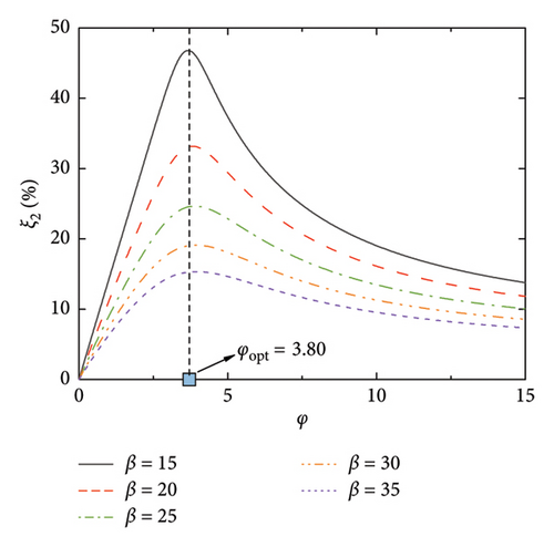
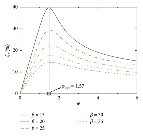
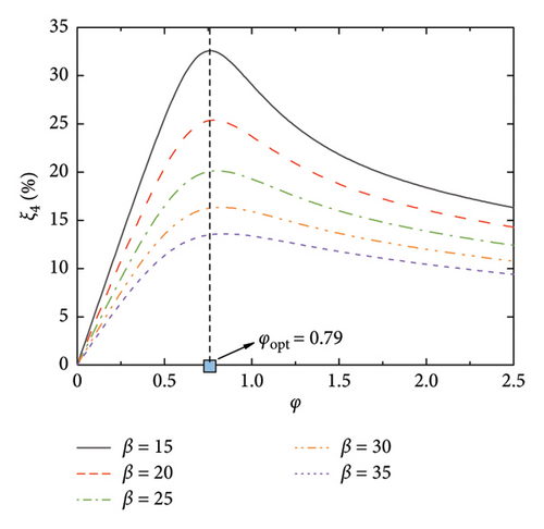
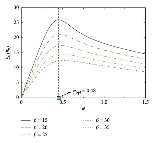
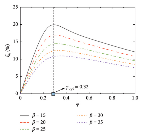
Figure 3 shows the frequencies of the control system, where the modal frequencies are normalized by the first modal frequency of the SRB without control. Thus, φ = 0 reflects the frequency ratios among the modes without control, while, φ > 0 reflects the evolution of the modal frequencies versus the damping coefficient. As can be seen, the modal frequencies are basically identical to those of the uncontrolled SRB at small values of φ. However, with the increment of the damping coefficient, especially after reaching the values of φopt, the modal frequencies gradually increase till a certain value. When considering Figures 2 and 3 together, it can be observed that the significant increase in modal frequency when φ > φopt is the reason why the supplemental damping ratio decreases at large values of nondimensional damping coefficient. Another interesting phenomenon is the change of frequency ratios among the modes with the increment of φ. Taking Figure 3(a) as an illustration, the frequency ratios among the six modes fall within a certain proportional relationship at the first beginning. With the increment of the φ (for example, φ = 1), the frequencies of the 4-6 modes gradually increase, but the frequencies of the 1-3 modes remain unchanged. This phenomenon indicates that the introduction of the control system will not only provide supplemental damping to the SRB but will also move the higher modes away from the targeted one through changing the frequency ratios. This property may also be helpful in controlling the vibrations of the SRB, since the excitation frequencies (e.g., pedestrians or vehicles) are within a limited bandwidth.
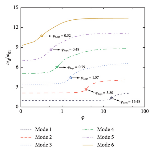
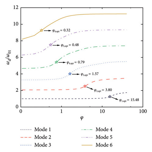
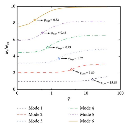
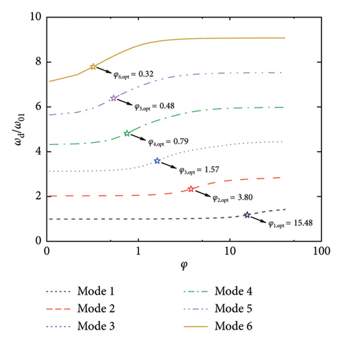
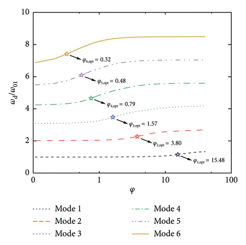
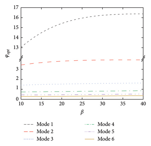
Figure 4 further summarizes the influence of geometric stiffness on the maximum supplemental damping ratios as well as the corresponding damping coefficients. As stated above, the maximum supplemental damping ratio decreases with the increment of geometric stiffness. However, even at a large value of β (e.g., 40), the supplemental damping ratio can still be quite considerable. For example, over 10% supplemental damping ratios can be provided to the first six modes herein. As for the optimal damping coefficients shown in Figure 4(b), they are generally less influenced by the change of geometric stiffness, especially for the higher modes.
3.2. Influence of Handrail Stiffness
The stiffness of the handrail is another important parameter, since it may influence the transfer of the control forces from the dampers to the SRB. To consider this influence, the spring element kri is involved in the governing equations, which are serially connected to the damper element. This layout is equivalent to the Maxwell model. The value of β adopts 25 and the other parameters keep identical with the above subsection.
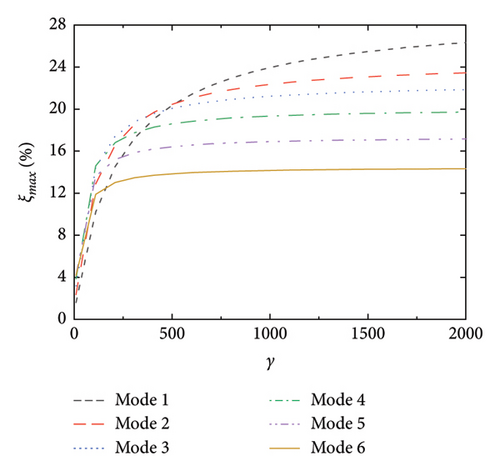
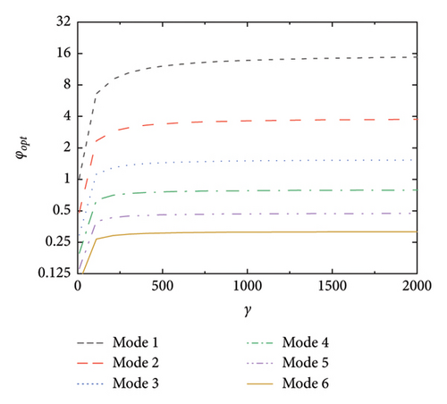
Figure 5(a) shows the maximum supplemental damping ratios and the corresponding damping coefficients versus γ (nondimensional stiffness of the handrail). When the stiffness of the handrail is quite low, the supplemental damping is also quite small. With the increment of handrail stiffness, the supplemental damping effect increases. When γ reaches 1000, the maximum supplemental damping ratios become less sensitive to the increment of γ. This indicates that the handrail should have enough stiffness to fully transfer the control forces to the SRB. Figure 5(b) shows the optimal damping coefficients versus γ. Similarly, once the rail stiffness reaches a certain value, its influence on the optimal damping coefficient becomes less obvious. Based on the above results, the rail stiffness should be carefully considered to balance the transfer of the control force and the strength requirement of the local connection between the handrail and the deck plate.
3.3. Influence of Damper Stiffness
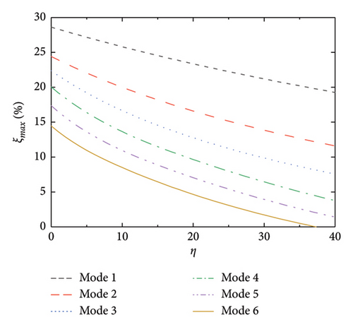
In this subsection, the influence of the damper’s stiffness is considered. To reflect its influence, the element kdi is involved and is connected with the damper element cdi in parallel. This layout can be equivalent to a Kelvin model. The values of the design parameters are consistent with the above subsections. The maximum supplemental damping ratios and the corresponding optimal damping coefficient are also calculated, as shown in Figure 6. As can be seen, the maximum damping ratio monotonously decreases with the increment of η (nondimensional stiffness of the dampers). Meanwhile, the optimal damping coefficient slightly increases with the increment of η. Based on the above results, it can be concluded that the increase in damper stiffness has a negative effect on the control system. In real applications, the damper stiffness should be minimized as small as possible.

3.4. Influence of Spatial Arrangement of the Rail Dampers
In the above subsections, the spanning distance of the dampers takes l/L = 1/10. However, for the same SRB, though the nondimensional damping coefficient φ is identical, the damping effect may be different with different rail-damper layouts. Thus, the different arrangements of the rail dampers, i.e., the different distance-to-length ratios (defined as α = l/L) are further investigated. It should be noted that an optimal arrangement of the rail dampers should consider the differences in the spanning distance as well as design parameters among the dampers. However, this will lead to a large amount of parameter analysis. Besides, the optimal layout of the rail dampers is also influenced by the structural and excitation properties. To simplify the analysis process and to obtain a more general conclusion, the rail dampers are assumed to be uniformly spaced with identical design parameters. The distance-to-length ratio varies from 1/2 to 1/12. A smaller value of α represents a smaller spanning distance as well as a larger number of the rail dampers.
The supplemental damping ratios with arrangements of the rail dampers are calculated, as shown in Figure 7. It can be observed that the smaller the value of α, the larger the supplemental damping ratios, and the larger the corresponding nondimensional damping coefficient that is required. This is because the relative deformation of the rail damper depends on the relative rotation between the two deck positions at which the handrails are installed. For a certain value of φ, a larger number of the rail dampers can better fit the deformation of the SRB, and thus achieve a larger relative deformation of the dampers.
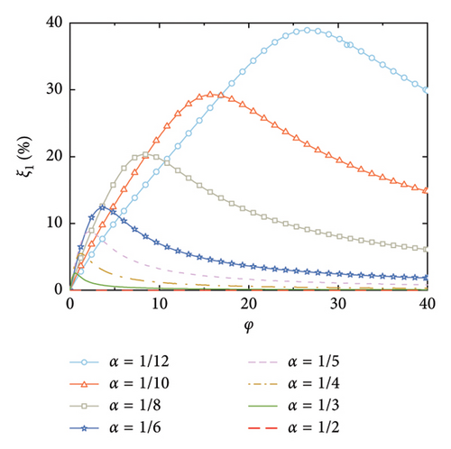
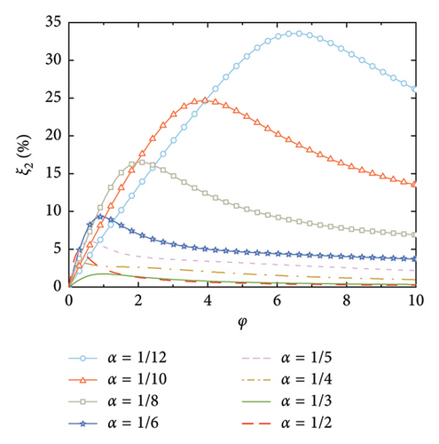
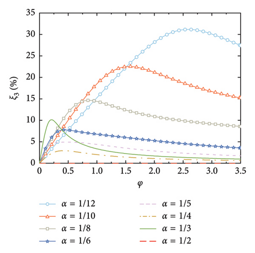
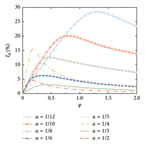
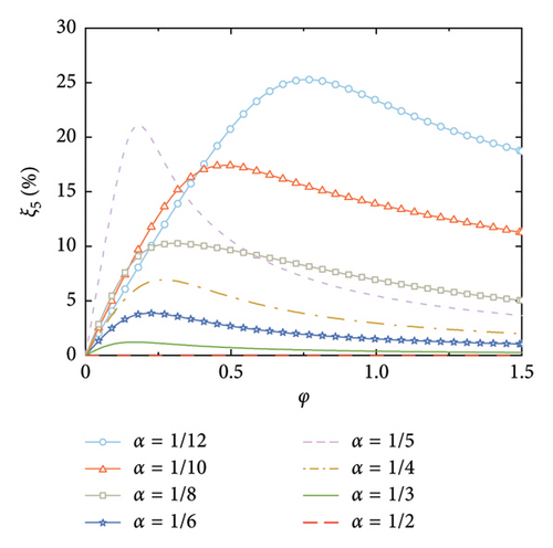
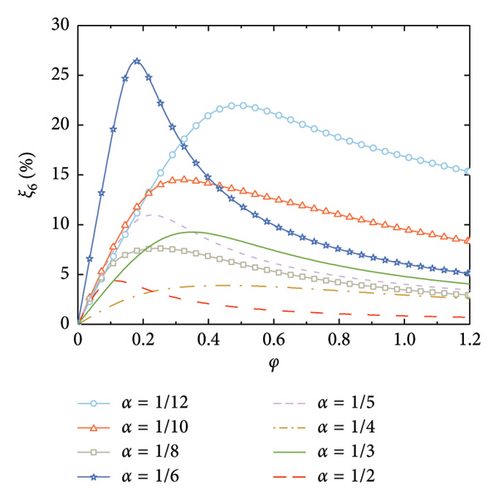
According to Figure 7, another interesting but important phenomenon can be observed as follows: once the distance-to-length ratio is reciprocal to the mode number (e.g., α = 1/4 for Mode 4 in Figure 7(c) and α = 1/6 for Mode 6 in Figure 7(f)), a much larger supplemental damping to this mode can be achieved at a relatively small value of φ, especially for the higher modes. For example, the modal damping ratio of the 6th mode can reach a value over 25% at α = 1/6 in Figure 7(f), which is significantly much larger than the other values of α in this Figure 7(f). This indicates that the required nondimensional damping coefficient can be reduced and a much economical control scheme can be achieved.
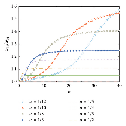
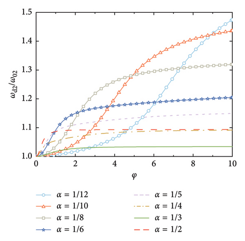
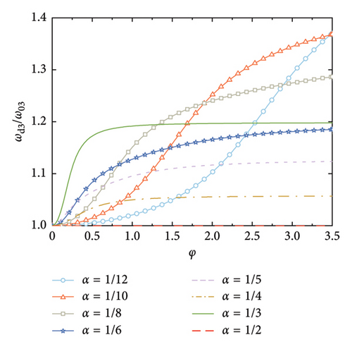
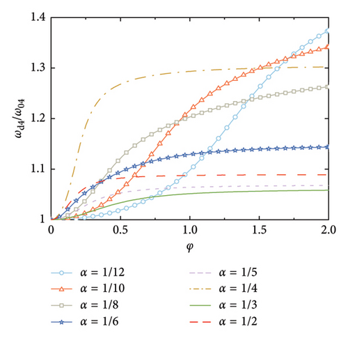
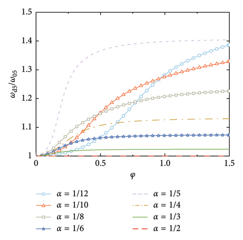
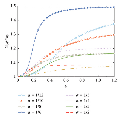
Figure 8 shows the nondimensional frequency of each mode, in which, the frequencies are normalized by the natural frequency of the SRB without control. The trend is identical to Figure 3, that is, the modal frequency gradually increases with the increment of the nondimensional damping coefficient until a certain value is reached. However, it is noticeable that once the number of the dampers equals the mode number (e.g., α = 1/4 for Mode 4), the modal frequency dramatically increases at small values of φ. This further validates that setting the number of rail dampers equaling to the mode number can significantly increase the supplied damping effect to this mode.
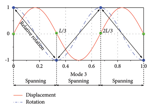
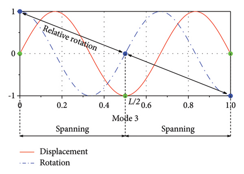
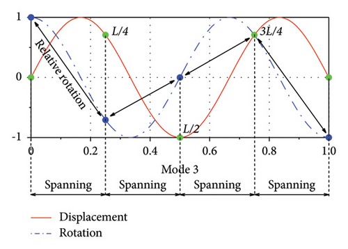
To further illustrate the influence of the distance-to-length ratio, the 3rd mode is selected herein for reference. Figure 9(a) shows the 3rd modal shape in both the vertical and rotational DOFs. As can be seen, when α = 1/3, the relative rotation between the two ends of each rail damper as well as the accumulated values of relative rotations for all dampers are the largest. This is the reason why this layout can achieve a much larger supplemental damping at a relatively low damping coefficient. Figures 9(b) and 9(c) show the results for α = 1/2 and α = 1/4, respectively. The relative rotations of the rail dampers are smaller than that in Figure 9(a), leading to a relatively smaller supplemental damping ratio for these two conditions.
4. Control Performance of the Rail-Damper System
4.1. Numerical SRB Model
To further investigate the control performance of the rail-damper system, a numerical case study is conducted. The numerical model is based on a real engineering application of the pedestrian SRB over the Sacramento River in California [36]. The total length of this bridge is L = 80 m. The width of the deck plate is 5 m. The mass of the SRB equals to m = 31 kN/m. The tensioning force of the ribbons at the completion state of the bridge is P = 1.49 × 10⁴ kN. The effects of live load and temperature variation on the tensioning force of the ribbons are ignored based on the assumption in establishing the governing equations. The other structural and material parameters of the SRB model are summarized in Table 1.
| Structural and material parameters | Variable | Load parameters | Variable |
|---|---|---|---|
| Bridge length L | 80 m | Mass m | 31 kN/m |
| Elastic modulus of concrete Ec | 3.5 × 10⁴ MPa | Horizontal force P | 1.49 × 10⁴ kN |
| Moment of inertia Ic | 0.0077 m4 | ||
| Rail height h | 1 m |
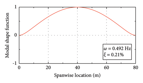
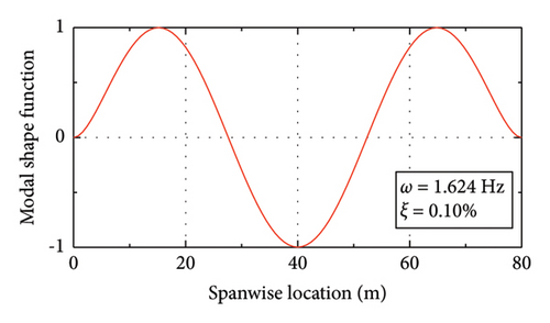
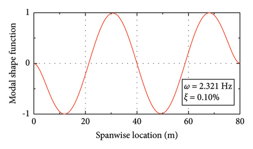
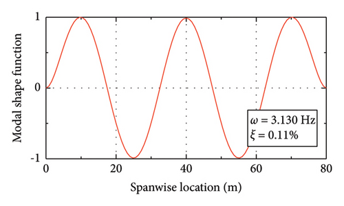
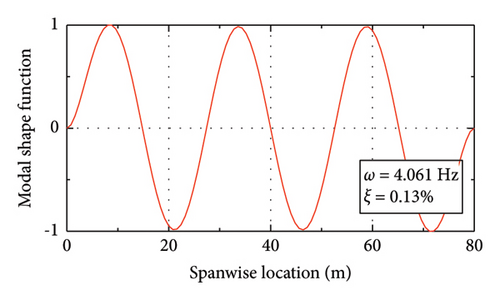
Figure 10 shows the modal properties of the first six modes. Due to the lack of damping data, the Rayleigh damping assumption is adopted in the calculation. Considering that the modal frequencies of the 3rd and 4th modes of this bridge fall within the pedestrian’s step frequency range (1.5 Hz–3 Hz), these two modes are adopted as the target modes in generating the Rayleigh damping matrix. A modal damping ratio of ξ = 0.1% is assigned to these two modes.

4.2. Pedestrian Load Model
| Walking frequency (Hz) | DLF | Phase angle |
|---|---|---|
| 1.5–3 | αz1 = 0.2817, fp = 0.2393, αz2 = 0.0895, αz3 = 0.0601, αz4 = 0.0577, αz5 = 0.0429 | φz1 = −π/4, φz2 = 0, φz3 = 0, φz4 = π/4, φz5 = π/2 |
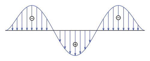
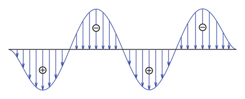
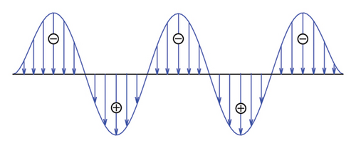
Since the main aim of this section is to validate the efficiency of the proposed control scheme rather than quantify the response properties of the bridge at all potential pedestrian activities, the above Fourier series–type force model is adopted in the following calculations. The gravity of the pedestrians is assumed to be G = 730 N. The walking frequency fp is within the range of 1.5–3 Hz. According to Figure 10, the modal frequencies of the 3rd–5th modes are within the pedestrian walking frequency range. In view of this, three walking frequencies (i.e., fp = 1.6 Hz, fp = 2.3 Hz, and fp = 3.0 Hz) are selected to consider the variations of the walking frequency. A crowd of 120 pedestrians are adopted in the calculation, which is assumed to be uniformly distributed on the SRB. The random movement of the pedestrians on the SRB is ignored. However, for each walking frequency, the distribution of the walking phases of the crowd varies based on the modal shape functions to better excite the target mode. For example, fp = 1.6 Hz is close to the frequency of the 3rd mode of the SRB. In this condition, the pedestrians on the middle one-third span length are assumed to have opposite phases with those on the two sides, as shown in Figure 11(a). The phase differences for the other two conditions are also shown in Figures 11(b) and 11(c), respectively.
4.3. Control Schemes
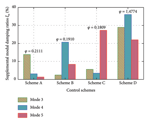
Based on the results in the above section, the 3rd–5th modes can be excited at different walking frequencies. According to the results in Section 3.4, once the distance-to-length ratio is reciprocal to the mode number, a much larger supplement damping to this mode can be achieved at a relatively small value of φ. Thus, four control schemes are investigated in this section. Scheme A corresponds to the most efficient layout for the 3rd mode (with α = 1/3). Scheme B and Scheme C correspond to the most efficient layouts for the 4th and 5th modes, respectively (α = 1/4 and α = 1/5). For comparison, a smaller distance-to-length ratio layout (Scheme D, α = 1/12) is also adopted, since a smaller value of distance-to-length ratio can achieve a larger supplemental damping to the SRB. For Schemes A–C, the design parameters of the rail-damper system (i.e., the damping coefficients) adopt the values of φ that can generate the maximum damping ratios for Modes 3-5, respectively (as shown in Figure 7). While, for Scheme D, the damping coefficient is determined through finding the value of φ that can maximize the sum of the damping ratios of Modes 3-5.
The supplemental modal damping ratios are then calculated for each control scheme and are shown in Figure 12. As expected, Scheme A achieves the highest modal damping ratio for the 3rd mode, as do Schemes B and C for the 4th and 5th modes, respectively, while Scheme D can provide relatively large damping ratios for all these modes. For example, the modal damping ratios of the 3rd, 4th, and 5th modes can be realized to about 25% in Scheme D. While, the 3rd mode in Scheme A, the 4th mode in Scheme B, and the 5th mode in Scheme C can achieve their maximum damping ratios with values of 14%, 21%, and 27%, respectively. Therefore, compared with the other schemes, Scheme D is expected to be more effective in controlling the multimode vibration of the SRB.
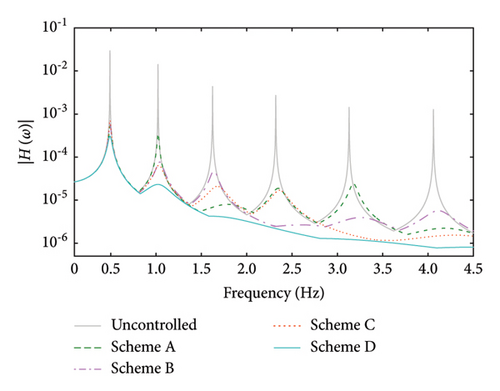
The frequency response functions of the uncontrolled and controlled systems are also calculated, as shown in Figure 13. As can be seen, the magnitude of |H(ω)| can be significantly reduced with the help of the control devices. For Scheme A, the magnitude of |H(ω)| is obviously reduced within the frequency range of 1.5–2 Hz, which is around the natural frequency of the 3rd mode. For Scheme B, the magnitude of |H(ω)| is significantly reduced within the frequency range of 2–3 Hz, which is around the natural frequency of the 4th mode. For Scheme C, |H(ω)| is significantly reduced within the range of 3–4.5 Hz (around the natural frequency of the 5th mode). While, for Scheme D, |H(ω)| has the smallest values within all the interested frequency ranges.
4.4. Control Efficiency and Comparison
To show the efficiency of the control system in a clearer way, the displacement and acceleration responses of the SRB are calculated. The displacement and acceleration responses of the 1/8 span point of the SRB with Scheme A are shown in Figures 14 and 15 as an illustration. The dash and solid lines represent the uncontrolled and controlled conditions, respectively. The static deformation of the bridge under the gravity of the pedestrians is removed from the time histories. As can be seen, with the help of the control devices, the response of the bridge can be obviously suppressed. For example, over 68% of the displacement responses can be reduced by the control devices at different pedestrian frequencies. In the meantime, the corresponding acceleration responses can be mitigated by about 84%–93% for different frequency conditions.
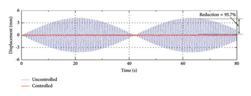
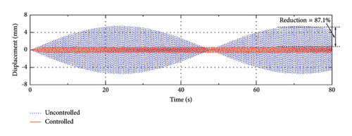
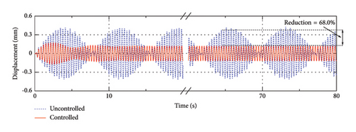

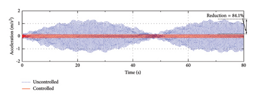

The displacement and acceleration reduction rates of the 1/8 span point with different control schemes are shown in Table 3. As can be seen, the control efficiencies of Schemes A–C are related to the frequency of pedestrian loads. When fp = 1.6 Hz, which is close to the natural frequency of Mode 3, Scheme A can achieve a relatively better performance than Scheme B and Scheme C, since this frequency mainly excites the 3rd mode of the SRB. Under higher walking frequencies (e.g., 2.3 Hz or 3.0 Hz), Schemes B and C perform better than Scheme A, since higher modes are excited by these walking frequencies. As for Scheme D, it performs quite well at all these walking frequencies.
| Schemes | Displacement reduction rate (%) | Acceleration reduction rate (%) | ||||
|---|---|---|---|---|---|---|
| fp = 1.6 Hz | fp = 2.3 Hz | fp = 3.0 Hz | fp = 1.6 Hz | fp = 2.3 Hz | fp = 3.0 Hz | |
| Scheme A | 95.7 | 87.1 | 68.0 | 92.9 | 84.1 | 87.5 |
| Scheme B | 77.3 | 98.3 | 81.9 | 75.5 | 97.8 | 94.9 |
| Scheme C | 88.4 | 88.0 | 88.7 | 86.7 | 88.0 | 95.3 |
| Scheme D | 96.6 | 99.0 | 96.6 | 93.2 | 98.5 | 96.9 |
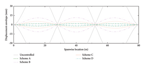
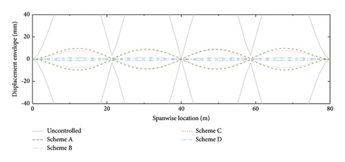
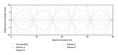
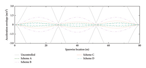
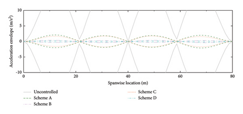
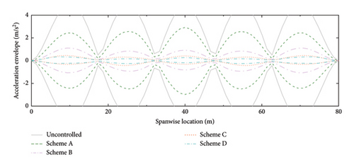
The displacement and acceleration envelopes of the SRB at different spanwise positions are shown in Figures 16 and 17, respectively. Similar to the above results, Scheme A has a good performance at low walking frequency. With the increment of walking frequency, the efficiency of Scheme A decreases, while the efficiency of Schemes B and C increases. In comparison, Scheme D has a good control performance at all these walking frequencies. Based on the above results, we can conclude that setting the distance-to-length ratio being reciprocal to the mode number can work well for the specific mode. However, the control performance is sensitive to the variation of walking frequency. To enhance the robustness of the control system, a smaller distance-to-length ratio layout should be adopted. Although more dampers are needed, both the control efficiency and robustness can be obviously improved.
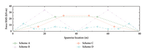
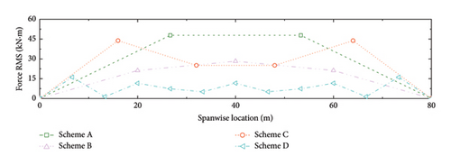
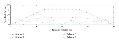
The resisting force of the dampers imposed on the SRB should also be considered since a higher resisting force also means a larger connection strength requirement between the deck slab and the handrail. The RMSs of the bending moments at the ends of the handrails (i.e., the resisting forces imposed on the SRB deck slabs) are calculated, as shown in Figure 18. In general, the magnitude of the bending moment decreases with the increment of the damper number. This is understandable since the increase in damper number can disperse the total damping forces and thus reduce the resisting force in each damper. From this aspect, Scheme D is also economically competitive. Even though this layout needs more dampers, the required connection strength between the deck and the handrail can be reduced.
5. Conclusions
- (1)
With the increment of nondimensional geometric stiffness, the maximum supplemental damping ratio decreases, but the optimal damping coefficient for a certain mode remains unchanged within the practical range of SRBs.
- (2)
A low stiffness of the rail can restrict the damping effect of the control system, while, a large stiffness of the damper can also restrict the damping effect of the control system. Based on practical considerations, a nondimensional rail stiffness of 1000 is recommended, and the damper stiffness should be restricted to as small as possible.
- (3)
The damping effect of the control system increases with the decrement of distance-to-length ratio. For a certain mode, setting the distance-to-length ratio reciprocal to the mode number can achieve a large damping effect with a relatively small damping coefficient. However, this layout only works well for this specific mode. The control performance is sensitive to the variation of excitation frequency.
- (4)
To achieve a broad-band control efficiency, the distance-to-length ratio should be set as small as possible. Even though this layout will increase the total number of dampers, the bending moments at the ends of handrails (the required connection strength between the deck slab and the handrail) can be reduced to some extent.
- (5)
It is noticeable that this study only investigated the key design parameters of the proposed system and validated its efficiency through numerical case studies. In real applications, the spatial layout of the rail-damper system can be further optimized through using global optimization algorithms. In addition, the performance of the rail-damper system can be further validated through onsite or scaled model tests of the stress-ribbon bridge.
Conflicts of Interest
The authors declare no conflicts of interest.
Funding
The authors gratefully acknowledge the support of the National Key Research and Development Program of China (Grant no. 2022YFB2602500), the National Natural Science Foundation of China (Grant nos. 52178447 and 52308299), and the National Postdoctoral Program for Innovative Talent (Grant no. BX20220026).
Acknowledgments
The authors gratefully acknowledge the support of the National Key Research and Development Program of China (Grant no. 2022YFB2602500), the National Natural Science Foundation of China (Grant nos. 52178447 and 52308299), and the National Postdoctoral Program for Innovative Talent (Grant no. BX20220026).
Appendix A: Element Matrices of Euler Bernoulli Beam
Open Research
Data Availability Statement
The data that support the findings of this study are available from the corresponding author upon reasonable request.


