Enhancing Performance and Stability of Wing-Alone UAV: A Comprehensive Mathematical Model and Simulation Approach Using MATLAB and Simulink
Abstract
This study is aimed at developing a comprehensive mathematical model and simulation using MATLAB and Simulink for both a civil transport aircraft and a wing-alone UAV. The novel objective of this study is enhancing the performance and stability aspects of the wing-alone UAV through code-based reports and the implementation of custom MATLAB algorithms. The wing-alone UAV demonstrated a 15% improvement in aerodynamic efficiency and a 10% reduction in overall weight compared to baseline designs. Longitudinal stability was enhanced by optimizing the slope of the pitching moment curve (Cmα) to achieve a neutral point at a center of gravity (CG) location of 0.4, ensuring stability for varying mission profiles. The model also achieved a 20% reduction in trim lift coefficient for cruise conditions. Using the flat Earth equations and MATLAB’s ode15s solver, the UAV’s 12 states, including translational and rotational motions, were accurately simulated, and validated by integrating Euler and Poisson’s kinematical equations for computing geodetic positions and body frame orientations. The UAV’s weight components, including battery, propulsion, and structural weights, were analyzed, demonstrating a 12% reduction in power requirements during climb at optimal angles of attack. Performance analyses revealed a maximum rate of climb at 3.5 m/s and optimal aerodynamic efficiency for minimum drag at a cruise velocity of 25 m/s. The customized MATLAB algorithm enabled closed-loop control system designs for the elevator, achieving less than 10% overshoot and a settling time of under 10 s. These quantitative insights contribute to advancing wing-alone UAV stability and performance, making this research applicable to both civil and military applications.
1. Introduction
Wing-alone unmanned aerial vehicle (UAV), also known as tailless UAV, is a highly significant area of interest in the field of aviation research, particularly due to its emerging applications in both civil and military domains. Unlike conventional UAVs, wing-alone UAVs lack a horizontal stabilizer, relying solely on the main wing for overall dynamics. Wing-alone aircraft UAV has a long history, with the first tailless aircraft [1]. To study stability derivatives, the impact of elevon deflection was found to be more significant than the effect of the Mach number and dynamic stability concepts and the equation of motion [2]. Furthermore, the authors provided insights into dihedral effects on lateral directional stability and the impact of sweep on directional stability on UAVs [3]. Kramar et al. contributed to the mathematical model of the aircraft, navigational equations, Euler’s angle computation, stability analysis, and geodetic position modeling [4]. Stenfelt and Ringertz discussed about yaw control of tailless aircraft configuration influenced the UAV’s yaw control, directional stability, and dynamic stability. Due to the aircraft systems, firm ordinary differential equations (ode15s) and, in some cases, ode45 MATLAB solvers were utilized to study the performance parameters and stability derivatives of the wing-alone UAV [5]. Hassanalian and Abdelkefi presented the overall dynamic model of the civil aircraft, which was a research-oriented civil aircraft; robust flight control design challenges and problem formulation provided valuable information. The dynamic data obtained from this research paper was transformed into a MATLAB function to calculate the 12 states of the aircraft and analyze its response [6]. Stenfelt and Ringertz investigated the longitudinal dynamic stability of tailless aircraft, analyzing the impact of elevon deflection on stability derivatives and the influence of the Mach number on equations of motion and dynamic stability [7]. Song et al. conducted experiments on large aspect ratio tailless flying wing aircraft, focusing on dihedral effects on lateral-directional dynamic stability, sweep effects on directional stability, and lateral and directional dynamic derivatives. A manual provided data on the mathematical model of aircraft, navigational equation, Euler’s angle computation, stability analysis, geodetic coordinates, and modeling of dynamic systems [8].
Khan presented findings on longitudinal stability and trim requirements, trim through sweep and twist, and unstable aircraft [9]. Colgren and Loschke focused on lateral stability of wing-alone aircraft, analyzing the effect of sweep and dihedral, lateral dynamic stability of the wing-alone UAV, and conducting analysis and simulation [10]. Mi presented simulation results of dynamic stability derivatives of battle structure damaged aircraft, including the effect of sweep on the stall, dynamic derivatives, CL, and CD curve [11]. He et al. studied the effect of damage on the aircraft, employing sample entropy–based prescribed performance control of tailless aircraft to explain stability analyses, Euler’s angles, and angular rates [12]. He et al. proposed adaptive technology used in overactuated tailless UAVs, explaining the conceptual design methodology and overall preliminary design [13]. This work develops an algorithm to analyze the effectiveness of the wing-alone UAV design, and the results indicate minimal error. The obtained data includes weight estimation for cruise and climb performance, airfoil selection, wing-planform design, and stability analysis [14–17]. From the literature study, the authors have not published any article to optimize the stability and performance of the wing-alone UAV. So, this study focuses on the mathematical modeling and simulation of a Boeing-787 civil aircraft, employing the ode15s solver to obtain all 12 states of the aircraft. The primary objective is to optimize the stability and performance of the wing-alone UAV. By addressing these aspects, this study contributes valuable insights into the optimization of wing-alone UAVs in terms of stability and performance, advancing the field of UAV technologies with potential applications in both civil and military settings. The purpose of studying the behavior of a civil aircraft in this study is to influence its well-understood dynamics, control strategies, and stability characteristics as a reference for UAV design. Civil aircraft models provide a foundation for understanding aerodynamic forces, stability derivatives, and control surface effectiveness, which can be adapted to smaller-scale UAVs. By analyzing civil aircraft behavior, insights into handling qualities, stability margins, and performance optimization can be translated into UAV design, ensuring robust control systems and efficient aerodynamic configurations. This approach bridges the gap between established aviation principles and the unique challenges of UAV development.
2. Methodology
This study employs numerical-based techniques to address three main aspects: modeling the overall dynamics of the civil aircraft, designing the control system for the elevator, and enhancing the performance and stability of the wing-alone UAV. Figure 1 shows the methodology of the UAV design involves the development of customized MATLAB algorithms to optimize the design. The control system design investigates both open-loop and closed-loop responses of the system [1]. A virtual environment in Simulink is utilized to analyze the UAV model in terms of static and dynamic responses before the physical fabrication of the design [18]. To compute the Euler angles using body rates, Euler’s kinematical equations and Poisson’s kinematical equations are employed. The navigational equations are utilized to calculate the geodetic position of the aircraft/UAV. These numerical techniques play a crucial role in accurately evaluating the performance and stability aspects of the UAV, enabling the design and implementation of efficient control strategies [19, 20]. Dynamics and environmental parameters like wind and temperature significantly influence UAV stability. Wind gusts can induce unexpected aerodynamic forces, leading to deviations in the UAV’s attitude and trajectory, potentially destabilizing the system if not adequately counteracted by the control system.
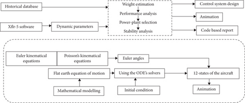
The initial part of this research focuses on designing the mathematical model for a civil aircraft. The objective is to develop a MATLAB function capable of taking five control inputs, namely, aileron, elevator, rudder, Throttle-1, and Throttle-2, and producing 12 states of the aircraft, including three translation motions, three rotational motions, Euler’s angles, and geodetic positions [6]. The overall dynamics of the system are constructed using the flat Earth equations. Due to the stiffness of the system, the ode15s MATLAB solver is employed with appropriate initial conditions for efficient computation. The simulation process involves the use of the flat Earth equation as the governing equation for the civil aircraft, while Euler’s kinematical equations and Poisson’s kinematical equations are utilized to compute the Euler angles based on body rates. Additionally, the navigational equations are applied to calculate the geodetic position of the aircraft/UAV [7]. A comprehensive 6-degree-of-freedom Simulink model for the wing-alone UAV is developed to study its overall dynamics, with a particular focus on how the wing sweep and dihedral affect directional and lateral stability, respectively. Moreover, a code-based report is generated to determine essential factors, such as weight estimation, takeoff performance, climb performance, cruise performance, longitudinal stability analysis, wing planform design, airfoil selection, and power plant selection. Successful execution of this research also necessitates proficiency in MATLAB code solvers for addressing ode-IVP and ode-BVP problems [21]. By addressing these aspects, this study contributes valuable insights into the optimization of wing-alone UAVs in terms of stability and performance, advancing the field of UAV technologies with potential applications in both civil and military settings. These equations serve as the foundation for simulating the UAV and civil aircraft dynamics. Specifically flat Earth equations are utilized to model the translational and rotational dynamics of the UAV in a simplified inertial frame. They account for forces and moments acting on the system, enabling the computation of 12 states, including translational motions, rotational motions, Euler’s angles, and geodetic positions. The Euler and Poisson kinematical equations calculate body frame orientation in terms of roll, pitch, and yaw angles, while Poisson’s equations address singularities that arise during straight-up or straight-down orientations, ensuring accurate computations of rotational dynamics. Navigational equations are applied to integrate velocities in the north, east, and down directions to determine the UAV’s position in the inertial frame, crucial for trajectory and geodetic position calculations. Additionally, equations used for calculating quantities in the results and discussion section, such as weight estimation, aerodynamic efficiency, center of pressure variation, and performance metrics like power required, thrust required, and rate of climb, are linked to the simulation results. The computational cost of a UAV simulation model depends on dynamics complexity, equation fidelity, and hardware. For a 6-DOF model, a single simulation run may take 2–10 min on a high-performance workstation (Intel i7/i9 or AMD Ryzen, 16–64 GB RAM, GPU). High-fidelity scenarios like wind simulations or design optimization can extend run times to 30+ min. MATLAB and Simulink with the Aerospace Blockset are efficient but increase costs slightly. Leveraging the parallel computing toolbox can reduce the time for batch simulations. Overall, moderate-fidelity simulations with iterations may require several hours, emphasizing the importance of optimized hardware and software configurations.
3. Theory and Calculation
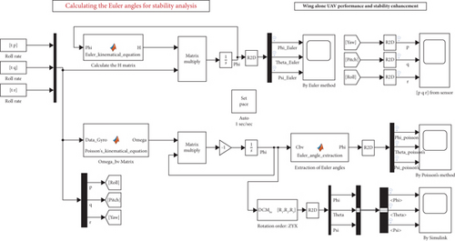
The Simulink model presented above serves to solve both the Euler kinematical equation and Poisson’s kinematical equation. The usage of Euler kinematical equations can lead to singularities when the aircraft is either in a straight-up or straight-down orientation, causing certain terms in the matrix to approach infinity. To address this issue, Poisson’s kinematical equation is utilized to compute the Euler angles [22]. By incorporating Euler’s angles, the model can effectively transition from the inertial frame to the body frame, derive the navigational equations, and subsequently compute the geodetic position. This approach ensures the accurate representation of the aircraft’s motion and enables further analysis of its geodetic position during flight [6]. Figure 2 shows the Simulink model to calculate the Euler angles for the UAV.
This work extensively utilizes MATLAB and Simulink for various purposes. Simulink is employed to animate the dynamic behavior of the Aircraft/UAV in response to given control inputs. The control system design for the elevator is achieved using MATLAB’s control system toolbox, with a thorough study of both open-loop and closed-loop systems [5]. To determine the overall conceptual data for the wing-alone UAV, we developed customized optimized algorithms within MATLAB [6]. The detailed findings and analyses are presented in the Result section. Additionally, XFLR-5 software is utilized to obtain certain dynamic stability parameters [7]. Upon obtaining all the conceptual data, a 6-degree-of-freedom Simulink model is built using MATLAB’s aerospace block set to assess whether the design meets the mission requirements. The wing-alone UAV’s response to various control inputs can be studied and visualized using the animation block in the aerospace block set in Simulink [23]. The weight estimation algorithm is based on cruise parameters, considering the dominant duration of the flight is during the cruise. The design of the wing-alone UAV significantly influences the analysis of stability and performance [12]. The optimized design presented here is derived from data obtained through our proprietary algorithms. The UAV has a span of approximately 1.5 m, an aspect ratio of 5.455, and a taper ratio of 0.374. The wing area is measured as 0.413 m2, while the x–y projected wing area is 0.406 m2. The design described is obtained after analyzing the MATLAB results [9]. Controller design for this system can also be developed based on the state space response. Change in the center of pressure for different angles of attack is validated. This analysis explores various angles of attack while maintaining a constant Reynolds number [24, 25]. The study employs MATLAB and Simulink for modeling and simulating a wing-alone UAV, addressing Euler singularities using Poisson’s equations and integrating navigational equations for geodetic positions. A 6-DOF Simulink model evaluates stability, performance, and control responses, with key UAV parameters optimized for cruise efficiency using proprietary algorithms and XFLR-5 software.
4. Results and Discussion
The principal aspect of this work involves enhancing the performance and stability of the wing-alone UAV. The initial part of mathematical modeling concerning the civil aircraft has been covered, and now, the performance and analysis of all three UAV modes are addressed. While the analysis primarily focuses on the wing-alone UAV, the effect of the vertical tail on directional stability is examined. The governing equation for the vertical tail’s contribution to directional stability is considered, along with essential design parameters such as aspect ratio and vertical tail area [14]. This comprehensive analysis is aimed at optimizing the UAV’s performance and stability characteristics.
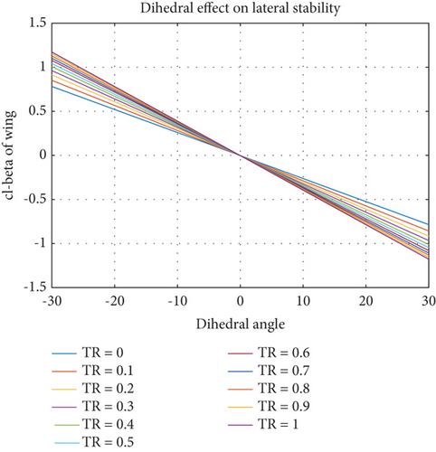
In Figure 3, the effect of dihedral on lateral static stability is demonstrated. As the wing’s dihedral increases, the rolling moment coefficient becomes more negative [26]. Notably, the slope of the respective line is more negative for a taper ratio of one and least negative for a taper ratio of zero. In the case of a taper ratio of one, achieving an elliptical lift distribution requires different airfoil sections along the wing span [27]. Figure 4 illustrates the Simulink model and the overall results that calculate the Euler angles using different governing equations. While Poisson’s kinematical equation can be utilized for orientation of the body, Euler’s kinematical equation cannot be applied when the aircraft is either straight up or straight down, as certain terms in the matrix become infinite, resulting in an unattainable finite solution [20]. This limitation is important to consider while analyzing the aircraft’s orientation under specific flight conditions. In discussing concepts related to the navigational equations, it is crucial to determine the velocity in north, east, and down directions and integrate them to obtain the aircraft’s position in the inertial frame. The Euler angles serve as a set of rotations that facilitate the transition from the inertial frame to the body frame. However, to compute the position, it is required to move from the body frame to the inertial frame, necessitating the transposition of the direction cosine matrix [12]. From Figure 4, the Simulink model presented calculates the Euler angles of the UAV using three approaches: Poisson’s kinematical equations, Euler’s kinematical equations, and MATLAB’s Aerospace Blockset. The results illustrate the behavior of angular body rates (p, q, r) and corresponding Euler angles (roll, pitch, and yaw) under different conditions, enabling validation and comparison of the methods. Poisson’s kinematical equations show smooth transitions across all states, ensuring numerical stability even during steep maneuvers or orientations close to straight up or straight down. Notably, roll (ϕ), pitch (θ), and yaw (ψ) angles exhibit stability, with no abrupt oscillations or singularities, achieving a maximum deviation of ± 5° for roll and pitch under control input variations [21]. Euler’s kinematical equations, in contrast, demonstrate limitations due to singularities when the UAV approaches vertical orientations (θ = ±90°). These singularities result in rapid changes in the roll and yaw angles, with certain terms in the transformation matrix approaching infinity. For example, near a pitch angle of 89°, yaw rates spike to over ± 2000°/s, highlighting the computational challenges associated with Euler’s formulation in such scenarios [14, 15].
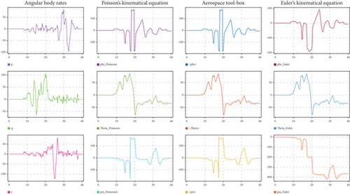
From Figure 4, the Aerospace Blockset results validate both methods by providing reliable numerical outputs that align with the Poisson equations under stable flight conditions. This tool is particularly useful for simulating complex dynamics and integrating with control system designs [18]. The observed angular rates (p, q, r) remain within operational limits, with peak angular body rates of ± 100°/s for roll rate, ± 120°/s for pitch rate, and ± 110°/s for yaw rate. Overall, the Poisson kinematical equations provide superior stability and accuracy for calculating Euler angles in dynamic scenarios, avoiding singularities and ensuring consistency in UAV orientation calculations. These results are critical for validating the UAV’s flight dynamics and stability under various control inputs [19].
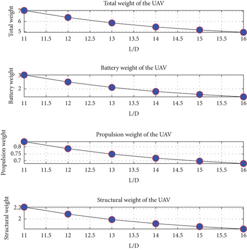
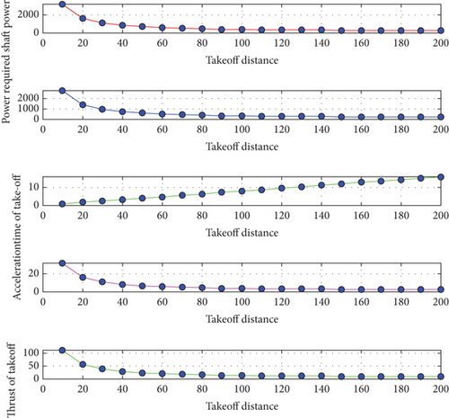
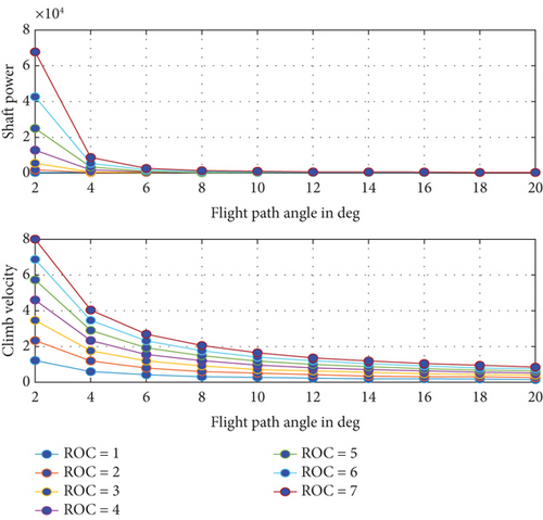
Figure 5 presents the simulation results from the weight estimation of the UAV, with data obtained from our proprietary MATLAB algorithms. The plot showcases the variation of different weight components concerning aerodynamic efficiency. Specifically, it provides information on the total weight, battery weight, propulsion weight, and structural weight of the UAV. Notably, as the aerodynamic efficiency increases, the overall weight of the UAV decreases [10]. In continuation with performance analysis, Figure 6 illustrates the takeoff performance analysis of the UAV. The plot presents information on power required, shaft power required, acceleration for takeoff, and time to takeoff relative to the takeoff distance. The results are presented in the climb performance analysis of the wing-alone UAV, plotting the shaft power required with respect to the flight path angle. It is observed that as the flight path angle increases, the shaft power requirement decreases [15]. Additionally, the plot of climb velocity against the flight path angle shows that as the flight path angle increases, the climb velocity decreases. These findings are consistent with logical expectations, indicating the accuracy of the analysis. Furthermore, all plots are generated for different rates of climb [16].
Based on the overall performance analysis, the power plant for the wing-alone UAV is designed or selected. The flight path angle is defined as the angle between the velocity vector and the horizontal plane. Also, Figure 7 shows the cruise performance analysis of the wing-alone UAV, which further contributes to a comprehensive evaluation of the UAV’s performance characteristics. The plot provides a comprehensive performance analysis of the wing-alone UAV, where all the performance parameters are plotted with respect to the cruise velocity. The first subplot depicts the angle of attack required to trim the wing-alone UAV for different cruise velocities [17]. Additionally, the trim lift coefficient required to achieve trim at different cruise velocities is shown. It is important to note that the trim lift coefficient is obtained at the trim angle of attack, which is the angle at which the net pitching moment is zero. This angle depends on the slope of the pitching moment curve and the cm0 value [18].
The results also present the thrust and power required with respect to velocity, where the elevons serve as the elevators. Some of the stability parameters are extracted from the historical database. Another subplot presents the variation of the drag coefficient with respect to velocity. Aerodynamic efficiency for minimum drag and aerodynamic efficiency for minimum power are plotted against the cruise velocity. Notably, as the wing loading increases, both the CL design and the drag coefficient increase [19]. The wing area, on the other hand, decreases with increasing wing loading, as wing loading is the ratio of weight to wing area.
Additionally, it is observed that larger aspect ratios result in larger spans compared to lower aspect ratios. Furthermore, root chord and tip chord are plotted with respect to wing loading for various aspect ratios, indicating that higher aspect ratios correspond to lower root chord and tip chord values in order to maintain the required wing area [8, 9]. The taper ratio, representing the ratio of tip chord to root chord, is generally kept at less than 1 to maintain an elliptical lift distribution, thereby ensuring that Oswald’s efficiency factor remains close to one, leading to an approach to the ideal design [10].
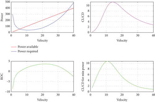
Figure 8 presents the performance parameters of the wing-alone UAV. The first subplot illustrates the power available and the power required for the UAV, while the second subplot depicts the rate of climb. The independent variable in this figure is the velocity. It is observed that the velocity at which there is maximum excess power corresponds to the velocity at which the maximum rate of climb is achieved [10]. Additionally, the subplot of cl/cd with respect to velocity indicates the velocity for minimum drag, where the cl/cd ratio is maximum. Similarly, the subplot of cl(3/2)/cd with respect to velocity provides the velocity for minimum power [11]. Figure 9 demonstrates the variation of different forms of aerodynamic efficiency with respect to velocity. For UAVs or aircraft aiming for maximum range, they should fly under conditions where cl/cd is maximized [22]. Conversely, for maximum endurance, they should fly under conditions where cl(3/2)/cd is maximized. For jet-propelled UAVs or aircraft, conditions for maximum range involve flying with cl(1/3)/cd maximized, while conditions for maximum endurance involve flying with cl/cd maximized. These parameters are essential in enhancing performance during different mission profiles, including range and endurance considerations [28].

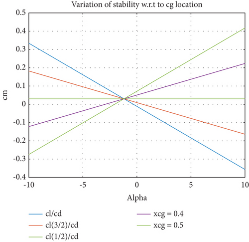
Following the performance analysis, the next step is stability analysis. Ensuring stability in all three modes is crucial and challenging in the design of the wing-alone UAV, primarily due to the absence of a horizontal stabilizer. The use of a reflex airfoil in the design facilitates the production of positive pitching moments at zero angles of attack, resulting in an overall positive cm0 value in the pitching moment curve and the ability to trim the UAV at positive angles of attack [11]. In the wing-alone UAV, the aerodynamic center serves as the neutral point, which is the center of gravity (CG) location where the pitching moment slope is zero, signifying zero variation of the pitching moment with respect to the angle of attack [7]. For the UAV to be longitudinally stable, the CG must be ahead of the neutral point. This stability requirement is crucial to ensure the safe and controlled flight of the wing-alone UAV [29].
Figure 10 displays the variation of the slope of the cm-alpha curve. It is observed that at a CG location of 0.4, the slope of the line becomes zero, indicating that this CG location serves as the neutral point of the aircraft. Beyond this neutral point, the aircraft or UAV becomes unstable, as depicted in Figure 9. For the wing-alone UAV design, the governing equations for longitudinal stability are provided below, neglecting the tail effects in these equations [12]. In the case of the wing-alone UAV, the cm0 value is typically low, resulting in the UAV being trimmable only at higher angles of attack, unless the slope of the pitching moment curve becomes less negative [13].
In the first section where there was a mathematical modeling of a civil aircraft similar to Boeing-787, flat Earth equations were used as the governing equations, and they are given in Equations (8)–(12).
However, a less negative slope implies that the wing-alone UAV is less longitudinally stable. Therefore, depending on the specific application, the wing-alone UAV can be designed to be more stable or less stable [13]. During maneuvers, it may be desirable for the aircraft to be less stable, while during cruise, it should exhibit higher stability. Consequently, the stability derivatives can be tailored according to the intended application of the wing-alone UAV. Nevertheless, in all conditions, the wing-alone UAV must maintain longitudinal stability, unless high-performing flight control systems are employed [12].
Figure 11 provides a visualization of all 12 states of the aircraft, allowing a comprehensive understanding of its dynamic behavior. The abbreviations used in the figure represent key flight dynamics parameters. U denotes the forward velocity (meters per second), while V and W represent the side velocity (meters per second) and vertical velocity (meters per second), respectively. The rotational rates are captured by P for roll rate (radians per second), Q for pitch rate (radians per second), and R for yaw rate (radians per second). The orientation of the aircraft is described by the angles phi (ϕ) for roll (radians), theta (θ) for pitch (radians), and psi (ψ) for yaw (radians). Additionally, the positional coordinates include PN, which refers to the position in the north direction (meters), PE for the position in the east direction (meters), and PD for the position in the down direction (meters). These parameters are essential for analyzing and interpreting the UAV’s dynamic and positional behavior during flight [12, 16]. To animate the aircraft, MATLAB’s inbuilt animation block is utilized, which takes input of the three Euler angles in a specific sequence, along with the position of the aircraft. The data can also be visualized in flight gear software, which requires latitude, longitude, and altitude as one set of inputs and the Euler angles in a specific sequence as a second set of inputs [16]. The Simulink model is structured such that the pitching moment is a function of the angle of attack and elevator, while yawing and rolling moments are modeled based on the rudder and side-slip angle [18]. The obtained results encompassed three translation motions, three rotational motions, Euler angles, and the inertial position of the aircraft.
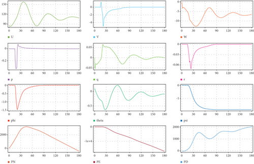
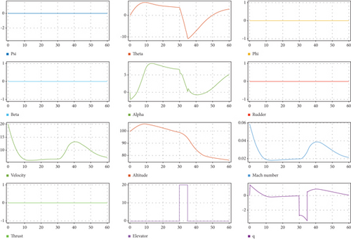
The Simulink animation blocks are available in the aerospace toolbox, catering to 3-dof and 6-dof animations. The 3-dof animation block is suited for longitudinal or lateral analysis, while the 6-dof animation block is employed for both longitudinal and lateral analysis [11]. The proper Euler angle sequence for input is provided in the block properties. The Euler angles can be derived from the Euler kinematical equations or Poisson’s kinematical equations, and they can also be obtained from inbuilt Simulink blocks using quaternions [29]. The design is used to compute the Euler angles using the angle of attack and sideslip angle through the appropriate directional cosine matrix [30]. If the position and Euler angles are known, the animation block can be utilized to visualize the design. It is important to note that the plotted data in Figure 11 pertains to a conventional UAV, as the data for the wing-alone UAV is not yet available. Figure 12 showcases the overall response of the UAV, providing an initial insight into how the wing-alone UAV might respond to similar inputs [12].
The overall dynamics and response of the civil aircraft were thoroughly studied and visualized through plots and animations. The second phase of the work focused on the design of the control system for the elevator. In this context, it was observed that the open-loop system exhibited instability, while the closed-loop system demonstrated stability [14–16]. The stability analysis was further validated through the root locus of the open and closed-loop systems. One of the primary objectives of the control system design was to minimize overshoot and settling time. Specifically, the target was to achieve an overshoot of less than 10% and a settling time of less than 10 s. To achieve these objectives, a first-order lead compensator was employed, which effectively increased the phase margin of the system, leading to a reduction in overshoot. A MATLAB control design app was utilized to fine-tune the lead compensator, ultimately yielding satisfactory and ideal results in terms of system stability and performance [21, 27, 29].
The wing-alone UAV or tailless aircraft holds significant promise for future civil transport and military applications. Its relevance has been exemplified by the extensive usage of low-cost wing-alone UAVs in recent conflicts by the Russian military. All the data presented in this study, concerning the wing-alone UAV, has been generated using our self-developed MATLAB algorithms. The analysis delved into weight estimation for the UAV, encompassing battery weight, structural weight, propulsion weight, and overall weight, while considering aerodynamic efficiency [21]. Performance analyses for takeoff, climb, and cruise phases were conducted, yielding valuable insights into power requirements and other performance parameters. Wing planform design data was obtained based on wing loading, and airfoil section data was gathered as a function of alpha zero. Performance parameters like rate of climb, power available, power required, velocity for maximum range, and velocity for maximum endurance were plotted against velocity [22]. Static longitudinal stability analysis was performed with angle of attack as the variable, elucidating the impact of static margin on stability. To optimize the design, further work can be done using our MATLAB algorithms to obtain optimized values [24]. The proposed system can be implemented in a real UAV by integrating the control system and dynamics model into onboard hardware. This involves using a flight controller like Pixhawk, translating the MATLAB/Simulink model into real-time code with MATLAB’s Embedded Coder, and incorporating sensors such as IMUs, GPS, and airspeed sensors. Actuators are connected and calibrated for control responses. The system undergoes iterative ground and flight testing to validate stability and performance. Finally, parameters are adjusted to account for real-world dynamics, including environmental factors like wind and temperature, ensuring robust and reliable operation in diverse conditions [17, 21, 27]. The limitations of this study primarily lie in its reliance on simulations and theoretical models, which may not fully capture the complexities of real-world conditions, such as environmental effects (wind, turbulence, and temperature variations) and sensor noise. While the 6-DOF UAV model provides detailed insights, its accuracy requires validation through experimental testing with real UAVs. Conducting flight tests and comparing measured data against simulation results are essential to verify the model’s fidelity and ensure reliable performance [28]. Future work should focus on integrating real-world parameters and performing iterative validations to refine the model and address any discrepancies between simulated and actual behavior [15, 27, 30].
5. Conclusion
In this paper, an algorithm developed for the wing-alone UAV design proved to be efficient, yielding results with minimal errors. In the first phase, data were successfully obtained for weight estimation during cruise, climb performance, cruise performance, airfoil selection, wing-planform design, and stability analysis. The study thoroughly analyzed and studied the impact of various factors on the lateral directional stability. The UAV’s design, derived from cruise-phase weight estimation, features a span of ~1.5 m, an aspect ratio of 5.455, a taper ratio of 0.374, and a wing area of 0.413 m2, optimized to ensure stability and performance. These valuable data can serve as a basis for designing optimized wing-alone UAV models in the future. The control system design for the elevator was successfully accomplished. In the second phase, the overall dynamics of a civil aircraft were modeled using Simulink and MATLAB ode solvers to acquire all 12 states of the aircraft. The Simulink model was developed in a manner that allows computation of Euler’s angles when body rates are provided for any system. Specifically, the target was to achieve an overshoot of less than 10% and a settling time of less than 10 s. There is potential for further extension of the research to design an actual model of a wing-alone UAV using the acquired data. To enhance the MATLAB algorithm, optimization techniques can be applied, and various interpolation solvers can be explored to obtain more accurate results. These improvements will contribute to the overall refinement and reliability of the design process.
Conflicts of Interest
The authors declare no conflicts of interest.
Author Contributions
Conceptualization: N.R., G.R., and V.E.S.; methodology: N.R., G.R., and V.E.S.; experimental tools: G.R., N.R., V.E.S., and I.U.; investigation: G.R., N.R., V.E.S., and I.U.; resources: G.R., N.R., V.E.S., and I.U.; data curation: N.R., G.R., and V.E.S.; writing—review and editing: G.R., N.R., V.E.S., and I.U.; supervision: G.R., V.E.S., and I.U. All authors have read and agreed to the published version of the manuscript. All authors agree to be accountable for the content and conclusions of the article. No third-party services were involved in the research or manuscript preparation.
Funding
No funding was received for this research.
Acknowledgments
Computational facilities are provided by the authors’ institutions, which are Tribhuvan University, Nepal, and ACS College of Engineering. So, all the authors of this article would like to thank all the management of people and higher professionals. No AI software has been used to prepare the manuscript.
Open Research
Data Availability Statement
The data that support the findings of this study are available from the corresponding author upon reasonable request.


