A Newly Proposed Fixed-Time Terminal Sliding Mode Controller for a Class of Nonlinear Systems: Throttle Valve Study
Abstract
Throttle valves are widely used in piping processes including oil and gas energy. Quick and accurate control of the position of the valve and reducing the dependency on the initial conditions of the valve not only leads to a decrease in energy consumption but also takes advantage of increasing the productivity of the generator and saving the fuel entered into the turbine. In this article, a newly proposed fuzzy-regulated fixed-time terminal sliding mode control (TSMC) is performed for the nonlinear second-order electronic throttle valve (ETV) system in the presence of uncertainty and external disturbances. In addition, a fuzzy rule base is applied to regulate the coefficients of the switching control law to improve the convergence of state variables to the sliding surface and reduce the chattering phenomenon. The proposed method is compared with the fixed-time TSMC and backstepping sliding mode control methods, and the results show that the designed controller works well in reducing the chattering phenomenon by 38.66% and reducing overshoot by 75.46%. Also, increasing the convergence speed of the transient response to 0.33 s, reducing the tracking error, improving system robustness, and getting free from initial conditions are some advantages of the proposed method.
1. Introduction
Since throttle valve industrial equipment is widely used as a flow regulator of fluids such as steam and gas in piping processes [1], it has attracted the attention of many researchers. The fields of research related to throttle valves are controller design, friction and corrosion [2, 3], operational and economic analysis, and fluid structure analysis [4–8]. This study focused on the first field of research, which is controller design. Because electronic or pneumatic throttle valves exhibit nonlinear dynamic behavior and external loads that affect the state of the valve, it has become a challenging issue in engineering science. To increase the performance of the turbine, controllers and actuators are applied to convert electrical or pneumatic signals into mechanical ones to change the position of the valve quickly and accurately, which leads to managing energy consumption and increasing the efficiency of the generator which produces the energy. In addition, it helps reduce the fuel input to the turbine. When the load on the generator decreased, the fuel decrease command was applied to the throttle valve positioner. In this case, the controller must change the position of the valve quickly and accurately to maintain a constant frequency of 50 Hz. By doing this, the consumption of fuel input to the turbine, which can be either gas or steam, is reduced, and it is also prevented from exiting the turbine with an overspeed alarm and the loss of stable energy production for the subscribers. In recent years, many control methods have been used to accurately control electronic throttle valves so that the system can follow the reference signal with acceptable accuracy. A proportional–integral–derivative (PID) controller to adjust the throttle valve using the moth flame optimization algorithm was proposed in [9]. Reference [10] utilizes a fractional-order PID controller whose controller coefficients are modified by the gray wolf optimization algorithm. Owing to the effectiveness of sliding mode controllers (SMCs) against disturbances and uncertainties, the combination of PID controllers with SMC has been proposed in recent years [11, 12]. Recently, hybrid controllers have been used to combine the advantages of each controller. These nonlinear hybrid control approaches, including adaptive backstepping integral SMC, are used for speed control of direct current (DC) motors with multiple inputs and multiple outputs [13]. The proposed method performed well against load disturbances and uncertainties. In [14–17], adaptive SMCs were utilized to control the valve position. The control strategy in [17] includes a recursive full-order TSMC based on the bilimit homogeneous property, which effectively suppresses the chattering phenomenon. Reference [18] proposed a fixed-time sliding-mode observer-based controller for uncertain nonlinear double integrator systems. A new form of a sliding mode observer in combination with a SMC is designed to estimate unknown parameters and states. In [19], a fuzzy adaptive fixed-time SMC method was proposed to track the trajectories of a high-order nonlinear system that faces mismatched external disturbances and uncertainties. Additionally, a fixed-time state observer was applied to estimate the unmeasured states. Reference [20] proposed a continuous fixed-time SMC for servo motors. In [21], a robust fixed-time SMC is defined, which is cooperating with a fixed-time sliding mode observer to solve the tracking problem in flexible joint robot-attached drones. First, the underactuated robot is modeled, and then, based on the availability of the measured states, a cascaded system is constructed to estimate the unmeasurable variables in a fixed time. In [22], a TSMC was proposed which guarantees finite-time convergence and achieves acceptable robustness against lumped disturbances. A cascaded finite-time sliding mode observer was also constructed to estimate the states and reduce the peaking phenomenon. Changing the parameters of the system owing to long-term operation causes a chattering phenomenon in the control signal [23]. Although the sliding mode control method is not sensitive to changes in parameters and external disturbances [24], it usually suffers from chattering. In [25], the use of neural networks for system training was suggested, which depends on information, and the chattering phenomenon was also clearly observed. Backstepping control based on Kalman filters was proposed in [26] to reject the disturbance and suppress noise in throttle valve control. Backstepping control based on barrier functions has also been proposed to ensure the stability of the entire nonlinear system [27]. In Table 1, the control strategies that have been recently used for throttle valve control are reviewed. As we have proposed an improved SMC, this review focuses on this field of research.
| Controlling method | Reference | Advantage | Disadvantage |
|---|---|---|---|
| Classic SMC |
|
|
|
| Integral SMC | Li et al. (2017) [32] |
|
|
| TSMC |
|
|
|
| Adaptive SMC |
|
|
|
| Fuzzy control and fuzzy SMC |
|
|
|
| Extended PID |
|
|
|
| Dynamic optimization |
|
|
|
| Neural network–based feedback tuning methods | Amico et al. (2023) [25] |
|
|
| Reinforcement learning |
|
|
|
| Barrier Lyapunov function–based adaptive control | Wang et al. (2021) [27] |
|
|
The Sliding mode control method and its related developments are suitable controllers for ETV due to their accuracy and robustness. In this paper, a fixed-time TSMC which is adjusted by fuzzy rules is proposed. TSMC proposes finite-time convergence regarding their nonlinear sliding surface. Considering that throttle valve industrial equipment is very sensitive and is used in sustainable energy supply, the state variables must reach equilibrium in a fixed time which is not dependent on the initial conditions of the system. In addition, in this study, fuzzy rules were used for adjusting the switching law. The presence of chattering phenomena and chaotic movements in the control signal applied to an electronic throttle dynamical system leads to challenges such as increased energy consumption, more control effort, reduced valve life, and increased valve friction, and as a result, it will increase controlling costs [45]. External disturbances in throttle valves are inevitable owing to their installation in industrial environments. These disturbances are usually caused by the valve which is sometimes stuck to the valve body, corrosion of the valve plate, vibration of other devices [43], and measurement noises. Therefore, robustness has been investigated and emphasized in this article to guarantee stability in the presence of uncertainties and disturbances. As the throttle valve is installed in the power plant, vibrations are one of the most significant disturbances that affect the position of the valve. In addition, the throttle may wear on the valve body which causes uncertainty in the parameters. Inevitable electrical noise, caused by generators and power cables, sometimes enters the shield and affects sensitive equipment. Accordingly, the main motivation in this study is to design a controller which is resistant to the mentioned uncertainties and external disturbances and reaches equilibrium in a fixed time that is independent of the initial conditions of the system. The designed controller was tested on the dynamics of the electronic throttle valve system. Because the presence of the chattering phenomenon in the control signal causes substantial damage to industrial equipment, the chattering phenomenon is reduced by the proposed fuzzy rule base. To design the proposed control structure, in the second section, a dynamic model of an ETV system with unknown nonlinear terms and disturbances is presented. In Section 3, a robust control approach for an ETV system based on fixed-time TSMC and a fuzzy inference system is presented. The Lyapunov stability proof is investigated to guarantee the stability of the designed fixed-time controller. Adjusting the parameters and using the fixed-time sliding surface, the control objectives such as convergence speed, system consistency, and chattering reduction are investigated. Finally, the simulation and results of the designed controller are analyzed.
2. Mathematical Model and Preliminaries
According to Figure 1, ETV consists of a DC drive (powered by a chopper), a gearbox, a valve plate, a double return spring, and a position sensor [38]. The DC motor is responsible for adjusting the valve plate angle to control the amount of fuel entering [46] the internal combustion engine manifold or the turbine [31]. The goal is to follow the reference opening command with the plate. The presence of friction and uncertainty in the nonlinear dynamic equations of the throttle makes the use of nonlinear control methods attractive. Owing to the disturbance in the system, the use of advanced sliding mode control methods is suggested. In Table 2, the parameters of the system are introduced, and the parameters that affect the dynamic equations of the system are quantified.

| Symbol | Description | Value | Unit |
|---|---|---|---|
| kt | Constant torque of the engine | 0.016 | N·m/A |
| Ra | Armature resistance | 2.8 | Ω |
| kch | Chopper gain constant | 2.4 | — |
| kv | Electromotive force constant | 0.016 | V·s/rad |
| kpre | Spring tightening torque coefficient | 0.107 | N·m |
| J | Inertia coefficient on the engine side | 0.00115 | kg · m2 |
| kl | 16.95 | — | |
| ktf | Coulomb friction coefficient | 0.0048 | N·m |
| kf | Sliding friction coefficient | 0.0004 | V·m·s/rad |
| ksp | Spring elastic coefficient | 0.0247 | V·m/rad |
| θ0 | Default gas plate opening angle | 2 | Degree |
| ld | Upper band of external disturbance | 2.2 | N·m |
| La | Inductance of the armature | — | — |
| ia | Armature current of a DC motor | — | — |
| θ | Position and opening angle of the throttle valve | — | — |
| Angular velocity of a motor | — | — | |
| u | Input control voltage applied to the motor | — | — |
| ms | Throttle return spring torque | — | — |
| mf | Frictional torque | — | — |
| mg | Unknown gear backlash torque | — | — |
| Symbol | Formula |
|---|---|
| ζ21 | |
| ζ22 | |
| k1 | |
| k2 | |
| k3 | |
| g | (ktkch/klJRa) |
In throttle valve, d(t) denotes the unwanted vibrations of turbines, and accordingly, ld which is its related upper bound is considered to be ld = 2.2 N · m where ld = SUP(d(t)). In Table 3, the details of parameters related to throttle valve system dynamics are presented.
3. Controller Design
For the ETV system (9), a fixed-time terminal control law was designed such that the system trajectory converged to the origin in a fixed time. In addition, because chattering removal is very important in this industrial equipment, the fuzzy switching law was used to reduce chattering and adjust the controller parameters. These goals must be achieved in the presence of external disturbances and system uncertainties.
3.1. Design of Fixed-Time TSMC
In this section, a controller using a fixed-time TSMC approach is proposed. The proposed rule provides fast convergence and accurate tracking, independent of the initial conditions.
3.1.1. Mathematical Preliminaries
In this section, some basic definitions and lemmas are proposed to clarify the stability of the proposed controller.
Definition 1. Consider the following nonlinear system [18]:
Definition 2. The equilibrium point of the nonlinear system defined in (11) is globally finite-time stable if for any solution x(t, x0) of the system, the following conditions hold:
- •
It is globally asymptotically stable and any solution x(t, x0) of (11) reaches equilibrium at some finite-time moment.
- •
It is stable in the sense of Lyapunov.
- •
For any ε > 0, there exists a δ(ε) > 0 such that ‖x(t, x0) ‖ < ε for any ‖x0‖ < δ and t ≥ 0.
- •
It is finite-time convergent: x(t, x0) = 0, ∀t ≥ T(x0).
- •
There exists a settling function T, such that .
Definition 3 (fixed-time stability). The equilibrium point of the nonlinear system defined in (11) is fixed-time stable if and only if [47, 48]
- •
It is globally finite-time stable.
- •
The settling time T(x0) should be bounded according to the initial conditions. In other words, the upper bound of the settling time Tmax > 0 is independent of the initial conditions, that is, ∃T > 0 such that T(x0) ≤ Tmax for ∀x0 ∈ ℝn.
According to Definition 3, settling time is always independent of the initial conditions of the system and its value is bounded in constant time control methods.
Lemma 1 ([49]). Consider the following system:
Remark 1. As illustrated in Lemma 1, the settling time function has a limited upper bound which is independent of the initial conditions. In other words, it is only related to the design parameters m, n, q, p, α, and β. Consequently, the convergence time to the equilibrium points can be guaranteed.
Lemma 2 ([50]). For nonlinear system (12), assume that a continuously differentiable and radially infinite Lyapunov function V(x): ℝn⟶ℝ+ exists such that for each α, β > 0 and 0 < p < 1, q > 1 the following conditions hold. Then, the origin will be fixed-time stable, and the upper limit of the convergence time is calculated according to Equation (13) and is independent of the initial conditions:
Then, the equilibrium points are globally fixed-time stable for the system in (11) and the settling time function is bounded as T(x0) ≤ 1/(α(1 − p)) + 1/(β(q − 1)).
3.2. Design and Stability Analysis
To design the fixed-time TSMC, the following steps are considered.
The following assumptions have been taken into account for the design of the controller.
Assumption 1. It is assumed that vibrations generated by various mechanical equipment in the throttle system introduce uncertainties or disturbances into the dynamic model of the nonlinear system.
Assumption 2. In the design of the control law, due to issues such as equipment corrosion, it is assumed that the throttle system model has parameters with a limited range of variation.
Assumption 3. The upper bound of external disturbances is limited by known positive constants.
Assumption 4. It is assumed that the position and opening angle of the throttle valve, denoted by θ, can be measured.
Assumption 5. When using the TSMC rules, the position and opening angle of the throttle valve are assumed to be constant. The designed controller ensures the convergence of the sliding mode behavior in a constant time, independent of the initial conditions, even in the presence of finite uncertainties. As a result, the tracking errors are expected to converge to zero in a constant time interval.
Assumption 6. Given the existence of delicate apparatus within the throttle system, the extent of variations in control signals is deemed restricted to avert potential harm to the equipment during practical application.
Here, m, n, p, q are odd positive integers.
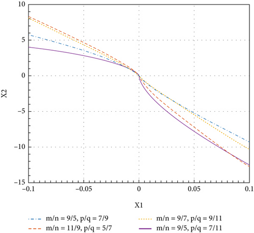
The figure below shows the sliding surface in the fixed-time TSMC according to Equation (15). As shown in Figure 2, the choice of control parameters affects the behavior of the sliding surface and ultimately affects the performance and stability of the system. The fractional power 0 < p/q < 1 and m/n > 1 affects how quickly the system state reaches the sliding surface and then the system converges to the desired state. It should be noted that if larger values are chosen for the parameters, the convergence rate will be faster, but it may lead to chattering phenomenon. In addition, the parameters should be chosen in such a way that fixed-time convergence is guaranteed.
- •
Sliding phase
Remark 2. According to Lemma 1, the system defined in (17) is fixed-time stable. In other words, the states converge to the origin in a fixed time [47].
- •
Reaching phase
u should be designed in such a way that states reach the sliding surface in a fixed time.
Theorem 1. For nonlinear system (9), the following controller is a fixed-time stabilizing controller:
terms are added to the controller to guarantee the stability. The controlling parameters are defined as follows:
Proof 1. To prove the stability, the following Lyapunov function is considered:
Derivation of (23) yields
Substituting controller (21) in (24) yields
Considering (μ + ld)|s| ≥ sd(t), it is concluded that which proves the system stability.
Proof 2. To prove the fixed-time stability, the following Lyapunov function is considered:
y is defined as follows:
Consequently, it yields
According to Lemma 2, the system is fixed-time stable.
3.3. Improving the Controller Efficiency by Fuzzy Defining of Coefficients
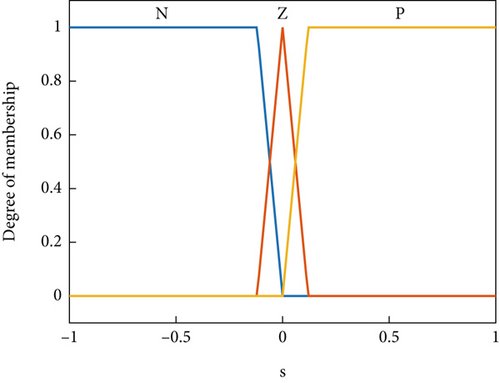
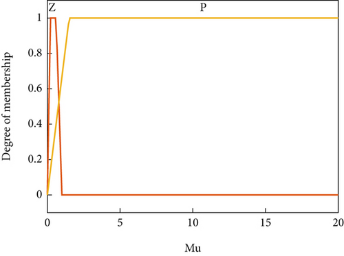
In control law (30), to reduce the chatter phenomenon and ensure Lyapunov stability, the switching control gain (μ) is selected in a fuzzy manner. Figures 3 and 4 show the membership functions related to the input s and the output μ.
3.4. Backstepping SMC Controller Design
Backstepping SMC controller is widely used for controlling nonlinear systems [56]. For example, the backstepping controller is applied to a six-degree-of-freedom (DOF) robotic manipulator model and is designed to perform well in the face of actuator and sensor errors [57]. In this paper, to analyze the performance of fixed-time fuzzy TSMC, the proposed method is compared with the backstepping SMC controller. The mathematical equations of the backstepping SMC method are expressed in Theorem 3.
Theorem 3. For System (9), the stable backstepping SMC controller is presented as follows [56, 58]:
Proof 3. The error equation is considered as follows:
To prove the stability, the following Lyapunov function is considered.
First step:
To guarantee , x2 must be chosen as follows:
The sliding surface is selected as follows:
Equation (36) is rewritten as follows:
The sliding surface is derived as follows:
Second step:
The Lyapunov function v2 is defined as follows:
The derivative of the Lyapunov function v2 is as follows:
For , the control signal u is chosen as follows:
By inserting the designed control signal into Equation (42), is guaranteed as follows:
The values c1 = c2 = 5 are selected.
4. Simulation Results
Figure 5 shows the external disturbance.
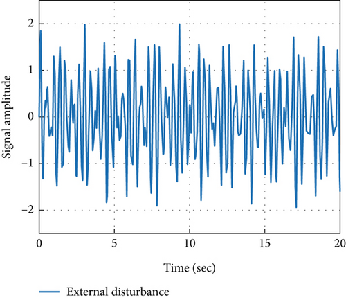
Figure 6 shows the block diagram of the controller, designed for the throttle valve.

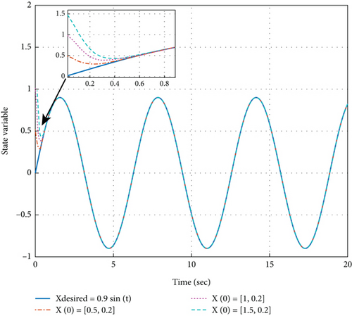
Figure 7 shows the success of the designed fixed-time TSMC for the ETV system in terms of convergence speed, accuracy, and especially independence from initial conditions x(0) = [0.5,0.2], [1,0.2], [1.5,0.2]. According to the values of the above parameters and Equation (13), the upper bound of the convergence time in reaching phase is 1.6 s and the upper bound of the convergence time in sliding phase is 1.15 s. As seen in Figure 7, the state variable converges to the reference signal in 0.54 s.
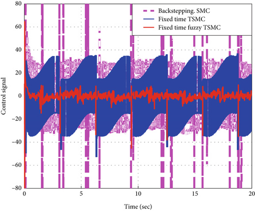
Use of the controller derived from a fixed-time TSMC strategy will damage the highly sensitive electronic throttle due to excessive chattering. Also, in the backstepping SMC method, the control signal has a lot of chattering. As seen in Figure 8, in the proposed fixed-time fuzzy TSMC signal, the chattering is effectively reduced.
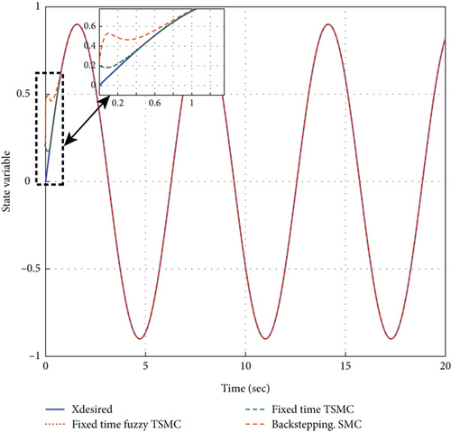
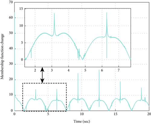
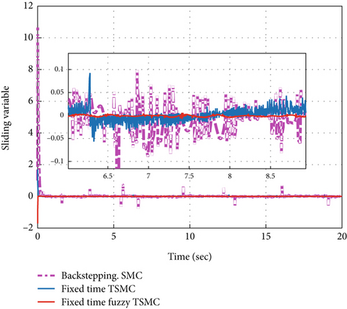
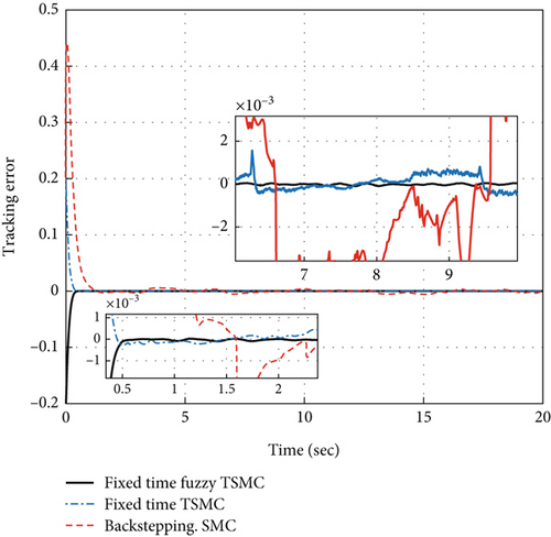
As can be seen in Figure 9, in both the fixed-time TSMC and fixed-time fuzzy TSMC methods, the convergence speed is reasonable and less than 0.33 s compared to [33]. The convergence speed in the backstepping SMC method is 6 s. The error performance indexes have been defined in Table 4. Considering Table 5 and Figures 8 and 9, it is clear that the method based on the fuzzy switching law has been very successful in reducing chattering, overshoot, and mean square error (MSE) index. All three methods have shown acceptable performance in reducing steady-state error. How the fuzzy term μ changes in the fixed-time fuzzy terminal sliding mode method can be seen in Figure 10. In Figure 11, it is clearly seen that in fixed-time fuzzy TSMC, the sliding variable has very few fluctuations and the system modes are attracted to the sliding surface, which leads to the reduction of the chattering phenomenon. Figure 12 shows how the tracking error signal becomes zero. In the fixed-time fuzzy terminal sliding mode method, the tracking error oscillates much less around the zero baseline and is clearly more accurate than in other methods. The evaluation results of the methods used in this article are presented in Table 5. Also, in order to accurately check the error reduction in different methods, the analysis of error values is illustrated in Table 6.
| Error criterion | Criterion formula |
|---|---|
| Mean square error (MSE) | |
| Integral square error (ISE) | |
| Integral absolute error (IAE) | |
| Integral time weighted square error (ITSE) | |
| Integral time weighted absolute error (ITAE) |
| Response specification | Steady-state error | Convergence time (s) | Overshoot (u) | Peak-to-peak controller variations |
|---|---|---|---|---|
| Fixed time TSMC | 3.24e − 4 | 0.4 | 34.96 | 87.85 |
| Fixed time fuzzy TSMC | 2.3449e − 4 | 0.33 | 8.58 | 53.89 |
| Backstepping SMC | 0.0011 | 1.5 | 80 | 160 |
| Response specification | ISE | IAE | ITSE | ITAE | MSE |
|---|---|---|---|---|---|
| Fixed time TSMC | 0.0025 | 0.0257 | 1.3483e − 4 | 0.0390 | 3.31e − 8 |
| Fixed time fuzzy TSMC | 0.0024 | 0.0271 | 1.4530e − 4 | 0.0621 | 1.75e − 4 |
| Backstepping SMC | 0.0397 | 0.1882 | 0.0051 | 0.5035 | 7.22e − 4 |
In Table 5, three control methods are compared, analyzed, and investigated in terms of some performance indexes. As it is clear from Table 5, the amount of steady-state error in the fixed-time fuzzy TSMC method is less than in other methods. Using the fixed-time fuzzy TSMC method, the system states converge to the equilibrium points of the system in 0.33 seconds that is guaranteed. Considering the fixed-time fuzzy TSMC method, it is clear that the chattering of the control signal is reduced by 38.66%, and the overshoot of the control signal is reduced by 75.46% compared to the fixed-time TSMC method.
Table 6 shows that the fixed-time TSMC and the fixed-time fuzzy TSMC methods have efficient performance. To discuss the results more clearly, they are analyzed in comparison with [33–35] results. In [33], an adaptive fixed-time full-order SMC is proposed for throttle valve control. Comparing the simulation results shows that our proposed fuzzy fixed-time TSMC performs more effectively in reducing chattering and convergence time. In [34], a fast nonsingular TSMC is proposed, which converges in 0.52 s. So our method performs more effectively in the sense of reducing convergence time. Reference [35] proposes an adaptive second-order fixed-time SMC, which is developed with disturbance observer compensation techniques. In comparison with this, our proposed method leads to less tracking error and controller vibrations.
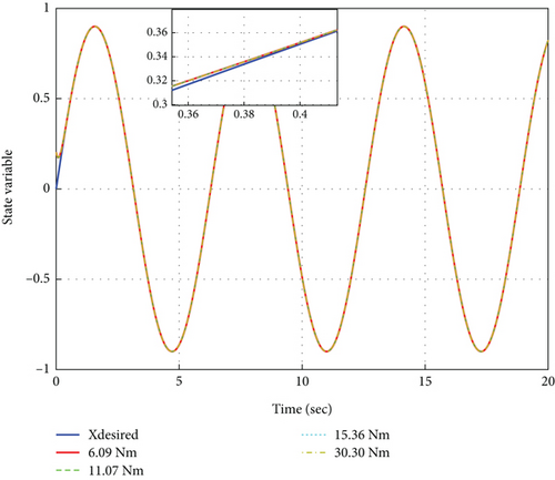
In Table 7, the amplitude of the disturbances becomes stronger and more destructive. Table 7 shows that with increasing the upper bound of the disturbance ld(t), the convergence time of the state variables to the equilibrium points remains constant and it is clearly shown that the fixed-time fuzzy TSMC method is a robust method. Also, with increasing the amplitude of the disturbance, the ISE error index in all modes is 0.0024.
| The upper bound of disturbance (Nm) | Convergence time (s) | ISE |
|---|---|---|
| 6.09 | 0.36 | 0.0024 |
| 11.07 | 0.36 | 0.0024 |
| 15.36 | 0.36 | 0.0024 |
| 30.30 | 0.36 | 0.0024 |
Figure 13 indicates that although the upper boundary of the disturbance (ld) increases and the disturbance intensifies, the fixed-time fuzzy TSMC method remains robust, the disturbance does not affect the system performance, and the proposed method has an effective performance in rejecting the disturbance. It can be seen from Figure 13, under all scenarios concerning the upper boundary of the disturbance, the system states converge very favorably to the input reference signal in a time constant of 0.36 s.
5. Conclusion
In this article, the problem of fuzzy fixed-time TSMC for the sensitive industrial equipment of ETV, which is a class of second-order nonlinear systems in the presence of uncertainty and external disturbances, is discussed. Although the proposed fixed-time TSMC has performed well in terms of fixed-time convergence, it suffers from chattering phenomena. Accordingly, a fuzzy regulation law has been added to the controller to reduce the chattering and prevent the erosion of industrial system parts. Fuzzy fixed-time TSMC is designed to achieve acceptable performance in terms of chattering and controlling effort reduction. Proof of fixed-time stability, discussed by the Lyapunov stability theorem, shows that the state variables of the system converge to the origin in a fixed time. The results of numerical simulations show the proper performance of the designed controller in reducing the chattering phenomenon to an acceptable level and improving the convergence speed of the transient response, reducing the error index and being resistant to external disturbances. It should be mentioned that, on the one hand, this paper considers some implementation limitations such as vibrations, friction of throttle with the valve body which causes parametric uncertainty, and the electrical noise caused by generators and power cables and penetrated into the shield; on the other hand, some other practical considerations such as input delay are neglected. So it will be beneficial to evaluate the efficiency of the proposed controlling method experimentally and analyze the technical conditions and the performance of the controller against the presence of noise in future works. It is also possible to take advantage of time-varying multisurface SMCs to improve controller efficiency.
Conflicts of Interest
The authors declare no conflicts of interest.
Funding
There is no funding or financial support related to this manuscript.
Open Research
Data Availability Statement
All the data used in the simulations are included in the text of the article.


