Field Uniformity Analysis in Cylindrical Reverberation Chambers for Slender Equipment Testing
Abstract
Aiming at the electromagnetic compatibility testing requirements of slender equipment, this paper proposes a design scheme for a cylindrical reverberation chamber. Through numerical simulation, the lowest usable frequency and field uniformity of the cylindrical reverberation chamber were analyzed. The results show that the cylindrical reverberation chamber has good field uniformity when the frequency is greater than , meeting the stringent requirements of IEC 61000-4-21. Utilizing this cylindrical structure for the reverberation chamber can effectively reduce testing costs and improve testing efficiency and accuracy. This research provides a foundation for further optimization of cylindrical reverberation chamber design, and it is expected to become an important tool for effective electromagnetic compatibility testing of equipment.
1. Introduction
For those slender equipment whose one-dimensional length is significantly greater than its other dimensions, conducting a complete set of electromagnetic compatibility tests presents certain challenges [1, 2]. These challenges arise in two main aspects. Firstly, whole-system electromagnetic compatibility testing in open fields faces constraints like adverse weather conditions and the testing site’s electromagnetic environment. These factors make it challenging to ensure the tests are convenient, repeatable, and comparable [3–5]. Secondly, when using anechoic chambers for testing, problems encountered include the high absorption loss of absorbing materials and the demand for a large amount of testing space, especially during radiated immunity testing, which requires the use of high-power Radio Frequency (RF) power amplifiers [6–10]. These devices are often monopolized by a few manufacturers, leading to a significant increase in the construction and testing costs of anechoic chambers [11].
In comparison, reverberation chambers utilize the high reflectivity of their internal metal surfaces to cause electromagnetic waves to reflect multiple times within the cavity, thus achieving efficient utilization of electromagnetic energy and creating a strong electromagnetic environment with lower input power. This characteristic allows reverberation chambers to reduce the dependence on RF power amplifiers during the electromagnetic compatibility immunity testing of whole weapons, significantly lowering testing costs and technical risks and becoming a feasible solution to the problem of whole-system electromagnetic compatibility testing [12–17].
However, traditional rectangular reverberation chambers, due to their large volume and surface area, significantly reduce the quality factor (Q-factor) of the chamber, meaning that rectangular reverberation chambers lose the advantage of generating high field strengths with low input power. The cylindrical reverberation chamber employs a cylindrical resonant cavity. This structural design is characterized by its simplicity in construction and ease of manufacturing, offering a higher Q-factor compared to rectangular cavities of similar volume. In 2011, NASA’s Space Power Facility (SPF) established a large cylindrical reverberation chamber with an internal diameter of 30.5 m and a height from floor to dome top of 37.2 m, utilizing an aluminum inner chamber [18, 19]. Although initial concerns were raised regarding potential energy focalization effects in such chambers, calibration experiments conducted by the National Institute of Standards and Technology (NIST) using a single stirrer with a diameter of just 1.4 m demonstrated that the SPF achieved field uniformity fully compliant with International Electrotechnical Commission (IEC) standard limits [20, 21]. Consequently, this paper explores the feasibility of utilizing cylindrical reverberation chambers for electromagnetic compatibility testing of slender equipment, analyzing methodologies for evaluating field uniformity.
2. Design Principles of Cylindrical Reverberation Chambers
2.1. Structure of Cylindrical Reverberation Chambers
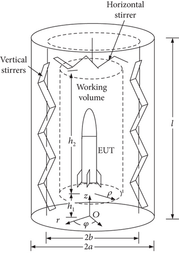
The structure of the cylindrical reverberation chamber is shown in Figure 1. The resonant cavity uses a cylindrical radius of a, and the height of the cylindrical reverberation chamber cavity is l. At a distance b from the cylinder axis, n vertical stirrers are placed, and one horizontal stirrer is set at the top of the cylindrical chamber. The stirrers are used to change the boundary conditions within the cylindrical cavity, thereby forming a statistically uniform field with random polarization inside the chamber.
2.2. Lowest Usable Frequency (LUF) of Cylindrical Reverberation Chambers
In the field representation expressions for TE and TM oscillation modes, the mode index m indicates the number of periods the field component varies along the circumference, which can be an integer value of 0, 1, 2, …; n indicates the number of half-standing waves along the radius a, which can be a nonzero integer of 1, 2, 3, …; p indicates the number of half-standing waves along the length l of the cavity, which can also be a nonzero integer for TEmnp modes and an integer for TMmnp modes.
According to the IEC 61000-4-21 standard [21], the LUF of the cylindrical resonant cavity can preliminarily be selected as three to six times the frequency of . Since the cylindrical resonant cavity structure and its inherent resonance modes differ from those of rectangular cavities, resulting in entirely different field distributions, this estimated value is for reference only. The specific LUF should be determined based on field uniformity.
3. Simulation Methods and Evaluation of Field Uniformity in the Cylindrical Reverberation Chamber
3.1. Establishment of Simulation Model Based on Method of Moments (MoM)/Fast Multipole Algorithm
The simulation model for the cylindrical reverberation chamber was established to analyze its field distribution and uniformity under operating conditions. For the modeling process, we adopted the MoM combined with the fast multipole method (FMM). This hybrid approach is particularly suitable for handling large-scale electromagnetic problems. This hybrid algorithm leverages the accuracy of MoM while significantly reducing the computational complexity and memory requirements through FMM’s hierarchical decomposition of electromagnetic interactions.
The structure of a cylindrical reverberation chamber used for whole-system electromagnetic compatibility testing of slender equipment is shown in Figure 2. The chamber has a sectional radius of a = 5 m and a height of l = 22 m. Two vertical stirrers are chosen, distributed around the axis of the cylinder at a distance of b = 4.125 m from the axis. The vertical stirrers rotate around their own axes with a rotation radius of 0.8 m, and the top horizontal stirrer rotates around the cavity axis with a rotation radius of 3 m. The two vertical stirrers adopt a “Z” shape structure, and the top horizontal stirrer adopts a “V” shape structure.
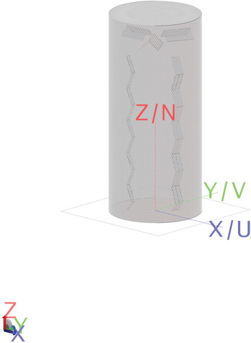
The working area of the reverberation chamber approximates a cylinder distanced ρ from the chamber’s axis. The distance between the working area and the stirrer should be at least λ/4. In this study, the working area of the cylindrical reverberation chamber is considered to be a cylinder with radius r = 2.5 m, starting at a height of h1 = 0.75 m from the ground, with a working space height of h2 = 18 m.
Based on the above parameters, the TE111 mode’s inherent resonance frequency of the cylindrical resonant cavity is 20.29 MHz. The chamber’s LUF is preliminarily selected as three times , approximately 60.86 MHz.
Leveraging the established simulation model, the chamber’s electromagnetic environment can be analyzed with high precision, offering a reliable framework for exploring field uniformity under diverse conditions. This comprehensive approach enables the systematic evaluation of key factors such as stirrer configurations, operating frequencies, and geometries of equipment under testing (EUT), ensuring an in-depth understanding of their impact on the chamber’s performance. These analyses, detailed in the subsequent sections, provide critical insights for optimizing chamber design and ensuring compliance with electromagnetic compatibility standards.
3.2. Evaluation Metrics and Validation of Field Uniformity
Typically, the field uniformity of rectangular reverberation chambers used for electromagnetic compatibility is evaluated using the Er, Eφ, and Ez electric field components; the total field strength Et; and its standard deviation at the eight vertices of the working space. However, in cylindrical reverberation chambers, where one dimension significantly exceeds the other dimensions, considering the attenuation of electromagnetic field propagation paths within the chamber, evaluating field uniformity based on the field strength at eight points in the working area is insufficient for cylindrical chambers.
This paper adopts a method involving three testing levels (upper, middle, and ground) in the working space of the cylindrical chamber, with four sampling points at radius ρ from the axis position Oi on each plane, totaling 15 sampling points to evaluate the chamber’s field uniformity. To ensure the randomness of the measurement data, the positions on the upper and lower planes can be rotated by appropriate angles, as shown in Figure 3 with α and β.
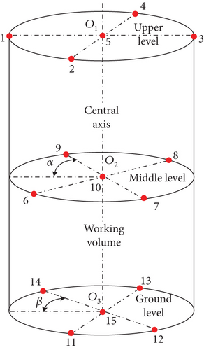
In the formula, σt represents the standard deviation of all vectors and Em,n refers to the values at m probe positions in n orthogonal vector directions within one stirring cycle. In this document, the cylindrical form has m = 15 and n = 3 (corresponding to the r, φ, and z directions, respectively).
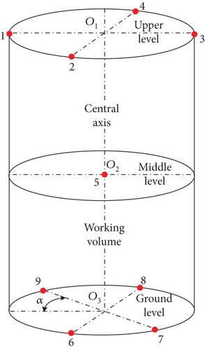
For frequencies greater than six times fs (LUF), where sufficient mode density ensures a statistically uniform field distribution, the number of sampling points can be reduced to optimize calibration and testing efficiency. Specifically, only the center point O2 on the middle level is retained, while four points on the circular edges of the upper and ground levels are preserved (Figure 4). This reduction maintains adequate representation of the field uniformity while significantly improving the efficiency of the measurement process.
This modification balances the need for maintaining statistical accuracy in field uniformity evaluations with the practical requirements of time-efficient testing in the cylindrical reverberation chamber. Such an approach is particularly beneficial for high-frequency testing scenarios.
4. Analysis of Field Uniformity for the Cylindrical Reverberation Chamber
To achieve uniform stirring, each stirrer rotates to four positions at lower frequencies; thus, three stirrers collectively achieve 43 stirring positions. The calculation and simulation determine the values for each component at 15 sampling points and obtain the maximum values. The standard deviations in the r, φ, and z directions σr,φ,z and the overall standard deviation σt are calculated according to the equations and presented in Figure 5.
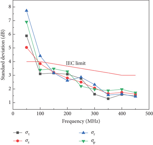
The results show that when the working frequency is three times the TE111 mode frequency (f = 60 MHz), the standard deviations in the r, φ, and z directions, as well as the overall standard deviation, exceed 4 dB. The field uniformity does not meet the standard requirements, with σr being greater than σz, suggesting that the field uniformity in the r direction is less than in the z direction. This is due to the smaller number of half-standing waves in the r direction of the slender cylindrical reverberation chamber, necessitating a higher working frequency to meet the field uniformity requirements. From Figure 5, it is observed that when the working frequency reaches six times , the standard deviations in all directions, as well as the overall standard deviation, fall below the 4 dB limit. This demonstrates that the field uniformity of the cylindrical reverberation chamber meets the required standard at this frequency, confirming that six times is an appropriate LUF for this design. The use of three stirrers in this configuration ensures efficient stirring, enabling a sufficiently uniform electromagnetic field distribution at higher frequencies.
5. Effects of EUT Volume and Geometry on Chamber Field Uniformity
According to the maximum EUT volume limit specified in IEC 61000-4-21 for reverberation chambers, the EUT and associated equipment should not occupy more than 8% of the total chamber volume. This requirement is crucial to ensure the stability and uniformity of the field environment inside the reverberation chamber. When the EUT is placed inside the chamber, it may impose a load on the chamber, absorbing some energy and thus reducing the chamber’s ability to generate the required test environment. To compensate for this load, it is necessary to increase the input power to the chamber. In order to limit the impact of reduced working volume on the load, IEC 61000-4-21 specifies that the volume of the EUT and all supporting equipment should not exceed 8% of the total chamber volume.
To evaluate how EUT volume influences field uniformity, we designed a gradient scheme, varying the volume ratios from 2% to 10%. This approach allows us to observe the incremental effects on chamber performance. Two cylindrical EUTs were used: one was a slender metal cylinder approaching a straight line, with a length equal to the height of the uniform field region minus λ/2 (Figure 6(a)); the other was a short and stout metal cylinder approaching a disk, with a radius equal to the radius of the uniform field region minus λ/4 (Figure 6(b)).
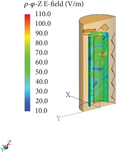
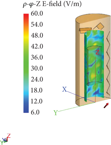
Numerical analysis conducted at 120 MHz, using the previously described method, yielded the results presented in Table 1. These findings reveal that even when the volume ratio falls within the standard permissible range, the inserted metal cylinders still impact the field uniformity in the reverberation chamber. Additionally, the shape of the tested metal cylinders plays a significant role in influencing field uniformity, potentially causing it to exceed the IEC limits. To ensure compliance, the length-to-radius ratio of the tested metal cylinders must remain within an appropriate range, as illustrated in Figure 7. Each cell displays the sample number and its corresponding value of σt. The color gradient represents the magnitude of σt, with darker colors indicating lower values and lighter colors indicating higher values.
| Number | Length of EUT (m) | Radius of EUT (m) | Length-to-radius ratio | Volume ratio (%) | σr (dB) | σφ (dB) | σz (dB) | σt (dB) |
|---|---|---|---|---|---|---|---|---|
| 1 | 16.50 | 1.82 | 9.06 | 10.00 | 4.37 | 3.70 | 4.47 | 4.20 |
| 2 | 16.50 | 1.63 | 10.12 | 8.00 | 3.80 | 3.79 | 3.75 | 3.78 |
| 3 | 16.50 | 1.15 | 14.34 | 4.00 | 4.48 | 4.53 | 4.61 | 4.64 |
| 4 | 16.50 | 0.81 | 20.37 | 2.00 | 4.60 | 4.60 | 4.30 | 4.62 |
| 5 | 12.00 | 2.14 | 5.61 | 10.00 | 4.62 | 4.95 | 4.72 | 4.83 |
| 6 | 9.60 | 2.14 | 4.48 | 8.00 | 3.91 | 4.56 | 4.43 | 4.33 |
| 7 | 4.80 | 2.14 | 2.24 | 4.00 | 3.82 | 4.23 | 4.26 | 4.13 |
| 8 | 2.40 | 2.14 | 1.12 | 2.00 | 3.67 | 3.89 | 3.78 | 4.04 |
| 9 | 8.25 | 1.63 | 5.06 | 4.00 | 3.65 | 3.83 | 3.73 | 3.76 |
| 10 | 9.78 | 1.63 | 6.00 | 4.70 | 3.93 | 3.97 | 4.01 | 3.98 |
| 11 | 11.41 | 1.63 | 7.00 | 5.50 | 3.59 | 3.73 | 3.81 | 3.86 |
| 12 | 13.04 | 1.63 | 8.00 | 6.20 | 3.79 | 4.10 | 3.80 | 4.05 |
| 13 | 14.67 | 1.63 | 9.00 | 7.00 | 3.75 | 3.81 | 3.58 | 3.76 |
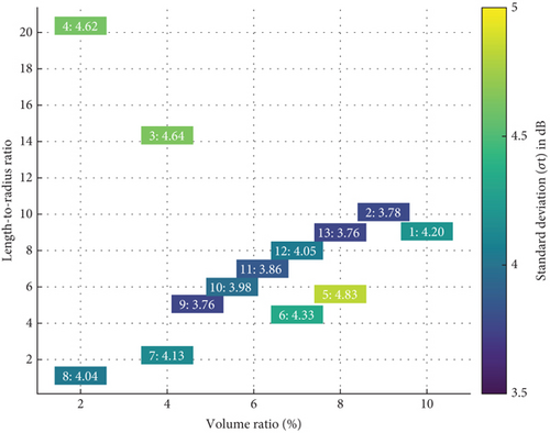
The heatmap reveals that the standard deviation of field uniformity (σt) tends to increase with higher volume ratios, indicating a potential decrease in field uniformity as the volume ratio rises. Lower σt values are observed at moderate volume ratios (e.g., 4%–6%) and length-to-radius ratios (e.g., 5–10), suggesting these combinations yield optimal field uniformity. Conversely, higher σt values occur at larger volume ratios (e.g., 10%) or extreme length-to-radius ratios (e.g., 20.37), indicating deteriorated field uniformity under these conditions. Sample 9 (volume ratio 4%, length-to-radius ratio 5.06) demonstrates the lowest σt (3.76 dB), representing a potentially ideal configuration. This analysis highlights the importance of maintaining moderate volume and length-to-radius ratios to ensure optimal field uniformity.
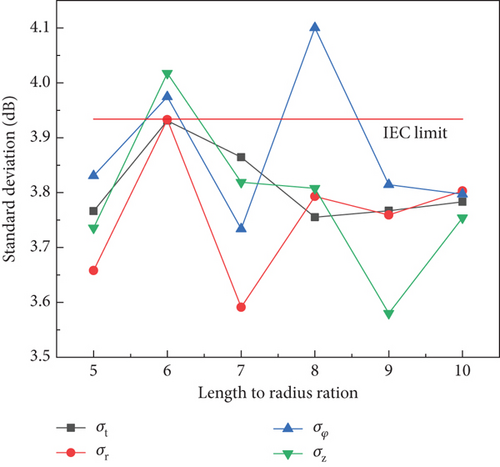
To further understand these findings, it is essential to investigate how both the volume ratio and the length-to-radius ratio of the EUT collectively influence the uniformity of the cylindrical reverberation chamber. Therefore, different length-to-radius ratios were set for analysis (Table 2), and the results show that when the volume ratio of the EUT to the chamber volume is within 8% and the length-to-radius ratio is between 5 and 10, the chamber’s uniformity meets the requirements of the IEC standard (Figure 8). This length-to-radius ratio also applies to the aerodynamic design principles of equipment such as missiles and rockets. Thus, the cylindrical reverberation chamber designed in this study can be applied to electromagnetic compatibility testing of slender equipment. However, for more complex shapes of EUTs (such as cruise missiles with wings), further specific analysis is required.
| Number | Length of EUT (m) | Radius of EUT (m) | l/r ratio | Volume ratio (%) | σr (dB) | σφ (dB) | σz (dB) | σt (dB) |
|---|---|---|---|---|---|---|---|---|
| 1 | 8.25 | 1.63 | 5.06 | 4.00 | 3.65 | 3.83 | 3.73 | 3.76 |
| 2 | 9.78 | 1.63 | 6.00 | 4.70 | 3.93 | 3.97 | 4.01 | 3.93 |
| 3 | 11.41 | 1.63 | 7.00 | 5.50 | 3.59 | 3.73 | 3.81 | 3.86 |
| 4 | 13.04 | 1.63 | 8.00 | 6.20 | 3.79 | 4.10 | 3.80 | 3.75 |
| 5 | 14.67 | 1.63 | 9.00 | 7.00 | 3.75 | 3.81 | 3.58 | 3.76 |
| 6 | 16.50 | 1.63 | 10.12 | 8.00 | 3.80 | 3.79 | 3.75 | 3.78 |
6. Conclusion
This paper proposes a cylindrical reverberation chamber structure suitable for electromagnetic compatibility testing of slender EUTs. The cylindrical chamber employs a stirrer distributed along the axis of the cylinder, operating in a mixed stirring mode with vertical stirring around its own axis and horizontal stirring at the top. The paper presents a method for calculating the standard deviation of the cylindrical reverberation chamber and conducts a simulation analysis of the chamber’s field uniformity. The analysis indicates that at lower operating frequencies, the cylindrical reverberation chamber exhibits larger standard deviations along the radial direction. This nonuniformity highlights the need for higher working frequencies to achieve acceptable field uniformity. Through analysis of different volume ratios and length-to-radius ratios, it is found that the volume and shape of the EUT significantly affect the field uniformity of the reverberation chamber. For EUTs with a volume ratio not exceeding 8%, cylindrical EUTs with length-to-radius ratios between 5 and 10 are suitable for electromagnetic compatibility testing in the proposed cylindrical reverberation chamber.
Disclosure
The funders had no role in the study design, data collection, analysis, or interpretation of results.
Conflicts of Interest
The authors declare no conflicts of interest.
Funding
This research was supported by the National Key Research and Development Program of China under Grant Number 5090903xxxx.
Open Research
Data Availability Statement
All data generated or analyzed during this study are included in the manuscript.


