A Broadband RCS Reduction Coating Using a Novel Arrangement of Metasurface Unit Cells Based on Two Substrates
Abstract
In this paper, a new coating structure is proposed for broadband radar cross section (RCS) reduction using 1-bit metasurfaces. The designed structure consists of two types of unit cell, arranged in concentric square rings. The substrate of unit cells is different, FR4 and Ultralum-2000 with thicknesses of 2.4 and 0.762 mm, respectively. The proposed structure shows an ultrawideband property to reduce the RCS, less than −10 dB, in the frequency range of 14–45 GHz. This range covers part of Ku-band (14–18 GHz), K-band (18–27 GHz), and Ka-band (27–40 GHz) and part of millimeter-wave band (40–45 GHz). To validate the designed work and simulation results, a prototype with the dimension of 84 × 84 mm2 is fabricated and tested. Also, the RCS reduction is determined analytically and presented. The measured results verify well the analytical and simulation results. In short, this work includes three new points: (1) the use of two substrates with different thickness and dielectric constant to design unit cells, (2) a new arrangement of array cells in the form of concentric square rings, and (3) achieving a great bandwidth to reduce RCS.
1. Introduction
With the development of radar systems and advancement of radar target detection and estimation methods, military stealth platform design has received much attention from researchers. Consequently, several researches have focused on the reduction of radar cross section (RCS), in the past decades. The known methods to reduce the RCS of the targets can be classified into two main categories: (1) conversion of electromagnetic wave energy into heat and (2) diffuse scattering (or cancelling of reflected waves from targets). Absorber materials [1, 2] belong to the first category. The second category includes the methods of shaping and use of the coating layers [3–6]. Planar coating layers are usually designed based on metasurface properties [7, 8], in order to control the phase and/or polarization of reflected waves for diffuse scattering. In addition to the aforementioned methods, the passive (or impedance loading) [2, 9] and active cancellation [3, 5] methods are also offered. Of course, using the active cancellation method inherently leads to an increase in cost and bandwidth limitation.
Design and implementation for each of the mentioned methods have its advantages and limitations, such as bandwidth, cost, complexity, weight gain, heating, and maintenance. Here, we follow with the metasurface-based design method, as a good option for diffuse scattering of the electromagnetic waves. Metasurfaces are artificial planar structures, periodically composed of unit cells, made by metals and/or dielectrics. These surfaces have attracted much attention from researchers due to their unique ability to manipulate electromagnetic waves in microwave and optical frequencies. This capability which is controlled by the physical and electromagnetic characteristics of the unit cells can lead to a wide range of applications such as antenna performance improvement, full absorption, super lenses, invisibility, and reducing the RCS of targets [7, 10–12]. In the following, we present a brief review of the reported researches, for application of the metasurfaces, to reduce RCS.
In 2014, a research team proposed a concept called metamaterial coding by digitally controlling material properties [13]. In this design, some material particles were used as digital metamaterial bits that were described by the effective parameters of the environment (e.g., silicon with a positive permeability coefficient and silver with a negative permeability coefficient). A more general concept of metamaterial coding can be expressed in such a way that in this case there is no need to examine the effective parameters of the environment. In this design, two types of unit cells are used with phase responses of 0° and 180° as “0” and “1” bits, respectively, under the title of 1-bit metamaterials. With a proper arrangement of these bits next to each other, electromagnetic waves can be easily controlled for different applications [14, 15].
By designing an artificial magnetic conductor (AMC) with a phase of 0° and a complete electrical conductor with a phase of 180° in a configuration resembling a chessboard, it is possible to eliminate reflections of normal radiation waves and reduce the RCS. However, the use of a perfect electrical conductor (PEC) decreases the frequency bandwidth of the structure. To enhance the bandwidth, an alternate AMC structure can be utilized instead of PEC cells, which operate at different resonant frequencies. These structures provide a phase difference of 180° in a more desirable frequency bandwidth [16, 17].
To increase the bandwidth, different approaches have been proposed for these structures, which are reviewed below: in [18], 50% bandwidth was obtained by arranging unit cells in a checkerboard pattern on a two-layer structure. The presented structure had a certain thickness of 0.14 λ0 (λ0 is the free-space wavelength corresponding to the center frequency) in the frequency range of 9.3–15.2 GHz. In [19], the bandwidth was increased to 63% by employing the same checkerboard arrangement with a distinct unit cell on a single-layer structure that had a specific thickness of 0.123 λ0 at 4.1–7.6 GHz frequency range. A single-layer structure with a thickness of 0.15 λ0 to achieve a bandwidth of 66% within the frequency range of 9.9–19.8 GHz was presented in [20].
In addition to 1-bit chessboard arrangement, other unit cell arrangements and phase distributions are also offered and employed, such as a spiral metasurface to reduce the RCS in the 12.2–23.2 GHz frequency band with bandwidth 62.1% [21], a parabolic phase distribution method to reduce RCS for incident angles ranging from 0° to 60° and 66.7% bandwidth [22], using the capability of independent phase control of two circular polarization, provided by four types of unit cells, to design a dual-circular polarization diffusion metasurface for RCS reduction (RCS_R), with 70% bandwidth [23], employing the wavenumber-splitting metasurfaces and parabolic phase subarrays to reduce the RCS in three frequency bands, with polarization and angle-of-incidence (0°–60°) stability [24], using various concave and convex parabolic-phased subarrays arranged in a chessboard pattern with random focal lengths, to achieve a bandwidth of 99.4% in the frequency range 7.8–23.2 GHz [25].
Furthermore, other important works have been reported in this area, such as multimode-assisted broadband impedance–gradient thin metamaterial absorber [26], LPDA-inspired material-geometry joint wide-angle broadband absorption based on metapyramid [27], adaptable invisibility management using kirigami-inspired transformable metamaterials [28], triple-band polarization-insensitive wide-angle ultraminiature metamaterial transmission line absorber [29], and deterministic approach to achieve broadband polarization–independent diffusive scatterings based on metasurfaces [30].
In this paper, two structures are proposed to reduce the RCS, which are suitable for broadband applications in four standard frequency bands. In these structures, 1-bit metasurfaces with two square ring unit cells are used, which have been analyzed, simulated, and fabricated in two different arrangements. Details of the paper are organized as follows: In Section 2, the design steps of two square ring unit cells with different dimensions are given. In Section 3, two proposed layouts of checkerboard and nested rings are analyzed. The measurement results and conclusion are given in Sections 4 and 5, respectively.
2. Design of Unit Cells
It is very important to choose a simple, economical, and single-layer unit cell in order to achieve the desired phase difference in a wide frequency band. Theoretically, to achieve −10 dB RCS_R, the optimal phase difference between cells should be about 180° ± 37° [19]. In this paper, similar to that performed in [31], we use two unit cells with different substrate thickness (Figure 1) but with the difference that the dielectric constant of the substrates is not the same. Really, one of the novelties of the current work is to use two substrates with different thickness and dielectric constant, simultaneously, in the unit cell design procedure. Ultralum-2000 and FR4 are chosen as the substrate of Unit Cells 1 and 2 due to their low cost and availability. The unit cell patches are square rings with copper thickness of 0.035 mm on these substrates. In Figure 1, P indicates the length of the unit cells which is 7 mm. In addition, L1, L2, h1, h2, and w indicate the length of the square ring of unit cell_1, the length of the square ring of unit cell_2, the thickness of the unit cell_1, the thickness of the unit cell_2, and the width of the square rings, respectively.
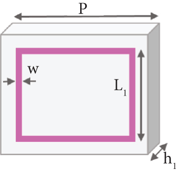
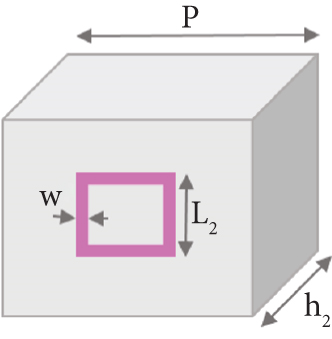
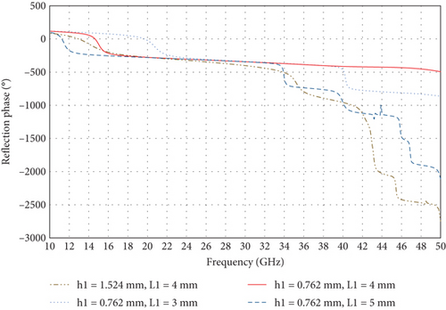
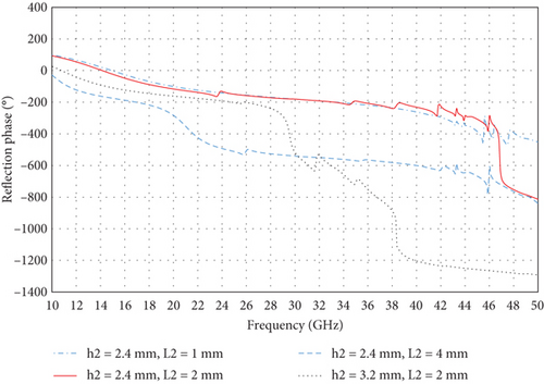
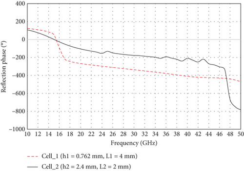
To simulate and analyze the proposed unit cells, HFFS software is used. By enforcing the appropriate boundary conditions, the reflection phase coefficient of the cells is determined. To achieve the desired phase difference, the parameters of the unit cells should be adjusted to the optimal values. Cell_1 is studied for the square ring lengths of 3, 4, and 5 mm and the substrate thicknesses of 1.524 and 0.762 mm. Similarly, cell_2 is also studied for different lengths of 1, 2, and 4 mm and the thicknesses of 2.4 and 3.2 mm. The reflected phase of cell_1 and 2 for different parameters is shown in Figures 2 and 3, respectively. According to the obtained results and considering the required phase difference of two unit cells, that is, 180° ± 37°, the final values for cell dimension have been selected. These values are available in Table 1.
| L1 | h1 | L2 | h2 | w | P |
|---|---|---|---|---|---|
| 4 | 0.762 | 2 | 2.4 | 0.3 | 7 |
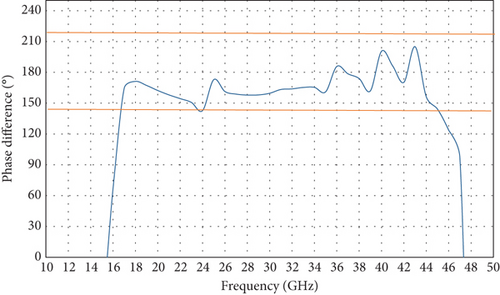
In the design procedure, we consider cell_1 and cell_2 as “0” and “1” bits in a 1-bit coding metasurface structure. In the following, we study two 1-bit coding structure, the conventional chessboard arrangement and the new arrangement introduced in this work. But before that, it is appropriate to review the frequency characteristic of the reflection phase for cell_1 and 2 and their difference phase, for final selected parameters of L1 = 4 and L2 = 2 mm (Figures 4 and 5). As can be seen in Figure 5, the desired phase difference of 180° ± 37° is available in the wide frequency range of 16.5–45 GHz.
3. Analysis and Simulation of the Proposed Structures
After designing the unit cells, the array elements should be placed next to each other with a proper arrangement, to reduce the RCS. In this section, two configurations including different arrangement of unit cells are considered to study. Figure 6 shows the first configuration that is a 2 × 2 chessboard arrangement. It consists of four 6 × 6 subarrays (or tiles). The elements of each subarrays are unit cell_1 or unit cell_2 as “0” or “1” bit.
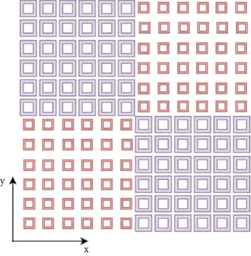
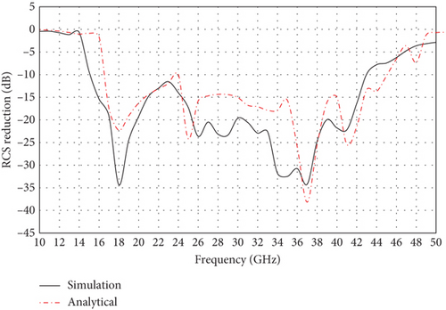
In order to simulate and calculate RCS_R of the proposed structure, CST commercial software has been used. To calculate RCS_R, the following two steps are required: simulating the structure to obtain its RCS and then subtracting the obtained RCS from a metal plate RCS, with the same dimension. Figure 7 shows the simulated RCS_R of chessboard structure. According to Figure 7, a wideband RCS_R (96.55%) has been achieved across a frequency range of 15–43 GHz. Additionally, Figure 8 depicts three-dimensional scattered power pattern at 25 GHz. It is clear that the reflected waves are directed to four main lobes.

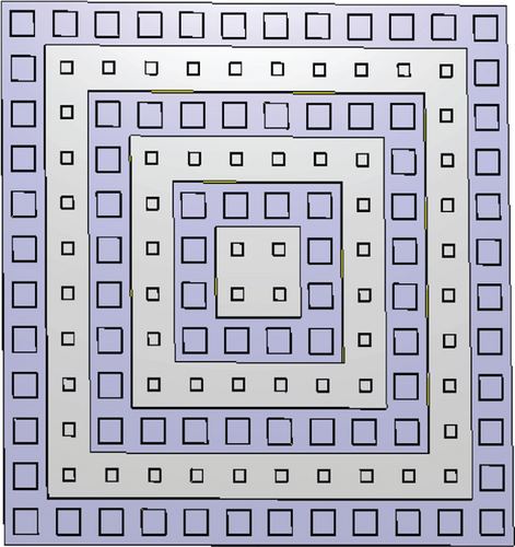
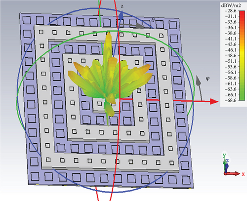
The second proposed configuration is a single layer nested ring structure, as a new unit cell arrangement, for 1-bit coding metasurface structure. This type of unit cell arrangement is introduced for the first time in this work. The proposed structure consists of six square rings nested within each other (Figure 10(a)). The dimensions of these rings are 84 × 84 mm2, 70 × 70 mm2, 56 × 56 mm2, 42 × 42 mm2, 28 × 28 mm2, and 14 × 14 mm2. As shown in Figure 10(a), from the inner ring to outer, unit cell_2 is embedded in the rings of 1, 3, and 5, and unit cell_1 is embedded in the rings of 2, 4, and 6, respectively. In order to show the capability of the proposed structure to reduce RCS, an example of its scattering pattern at 25 GHz is provided in Figure 10(b). As seen in this figure, the incident waves are diffused in different directions with lower energy levels.
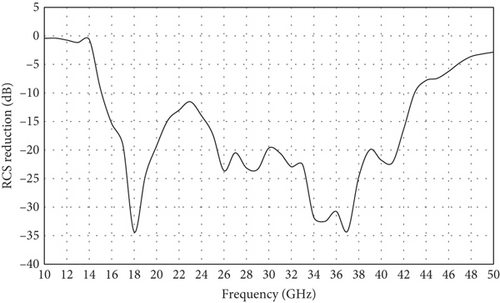
According to the obtained phase difference for two unit cells, which is shown in Figure 5, it is expected that the proposed structure has RCS_R feature in a wide range of frequency. Figure 11 shows the frequency characteristic of RCS_R, for the nested ring structure. Considering the −10 dB criteria, the RCS_R bandwidth is 105.1% and covers the frequency range of 14–45 GHz. Compared to the chessboard structure (Figure 6), with 96.55% RCS_R bandwidth, a good improvement has been achieved.
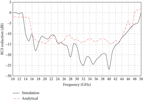
To determine the analytical RCS_R, the approximate Equation (4) is only for chessboard structure. Therefore, we should use the exact Equation (3) to calculate the analytical RCS_R for the nested ring structure. The method used is that first the scattering pattern in different frequencies is determined using simulation, and then, RCS_R is calculated using the exact Equation (3). The result of the performed analysis is available in Figure 11. According to this graph, RCS_R is below −10 dB in the frequency range of 16–45 GHz. Comparison and discussion of simulated and analytical results together with measured results will be done in the next section.
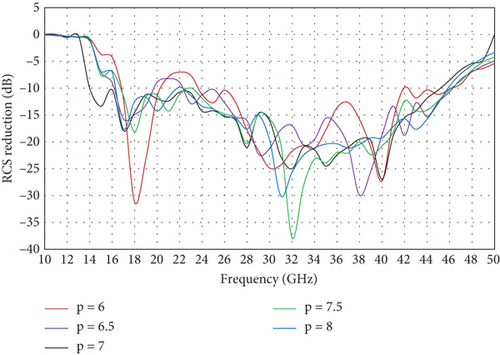
To study and investigate the effect of unit cell period on the RCS_R performance, we analyzed the proposed structure for different periods from 6 to 8 mm with 0.5 mm step. Figure 12 provides these results. As the results show, the effect of varying periods on the overall performance of the structure is quite evident, especially at the beginning and end of the frequency band. In addition, RCS_R degrades from 20 to 24 GHz for the case of p = 6 mm. It seems that p = 7 mm is the optimal value for the proposed structure.
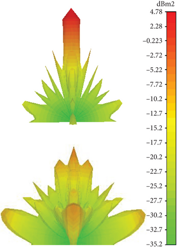
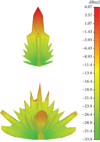
In order to investigate how the aforementioned structure diffuses the scattered waves in different directions, under normal incident condition, we determine the bistatic RCS pattern for three frequencies.
Figure 13 presents the bistatic RCS pattern of the proposed structure at 20, 24, and 41 GHz, compared to a perfect metal plate with the same dimension. It is clear that the reflected power in the normal direction is significantly suppressed compared to the metal plate at these frequencies.

4. Measurement and Discussion
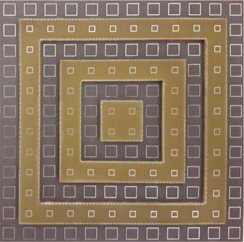
To fabricate and experimentally test a prototype, the nested ring structure is preferred over the chessboard structure for two reasons: (1) more RCS_R bandwidth and (2) for operational testing of the proposed structure. The nested ring structure is a new arrangement for RCS_R, and unlike the chessboard structure, so far it has not been tested in practice. The made prototype has the dimension of 84 × 84 mm2 and shown in Figure 14. The fabrication method is as follows: (1) making two arrays of 12 × 12 elements, one using unit cell_1 and the other using unit cell_2; (2) converting each of the arrays into an array of 2 × 2 and five square rings, by use of a cutting machine; and (3) locating the odd pieces of the array consisting of unit cell_1 and the even pieces of the array consisting unit cell_2, every other one, on a metal plate with dimension of 84 × 84 mm2, to form a final structure similar to Figure 14. The prototype was tested at SA Shiraz Industrial Company, using three pairs of standard horn antennas to cover frequency bands of 14–18, 18–27, and 27–40 GHz. Due to the frequency limitation of the required experimental setup, the RCS was only measured up to 40 GHz.
The analytical, simulation, and measured RCS_R are compared in Figure 15. As can be deduced from Figure 15, there is some deviation between the results. Differences between the analytical, simulation, and measured results are inevitable and usually created from several factors, such as manufacturing and measurement errors, Floquet mode errors (assuming infinite unit cells in the simulations), and neglecting cross-coupling between unit cells in the analytical model. Moreover, the misalignment of the horn antennas and target, reflections in the anechoic chamber and poor dynamic range of experimental setup, can arise deviation between them. In addition, the dielectric constant of FR4 becomes increasingly unstable in a wide and high-frequency range, leading to the shift of the resonance frequencies and more loss. Nevertheless, there is generally good agreement between the simulation and experimental results in terms of the overall trends. Anyway, each of the three results confirms that the proposed structure can reduce the RCS to less than −10 dB, in a wide frequency band, from 14 to 45 GHz.
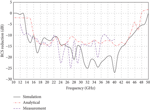
Table 2 compares the proposed structure performance with similar works in terms of the number of layers, bandwidth, frequency range, structure thickness, and number of frequency bands. According to Table 2, although the proposed structure has greater thickness than other works [18–20, 23, 32, 33], it covers a wider range of frequencies (14–45 GHz). This feature allows more frequency bands to be covered (part of Ku, K, and Ka and part of millimeter wave). In addition, the proposed structure is a single layer and has designed and implemented by lower-cost substrates, compared to the structures presented in [18, 23].
| Literature | Structure thickness (mm) | RCSR bandwidth (GHz) | Number of layers | Number of frequency bands |
|---|---|---|---|---|
| [18] | 0.14 λ0 | 9.3–15.2 | 2 | 2 |
| [19] | 0.12 λ0 | 4.1–7.6 | 1 | 1 |
| [20] | 0.15 λ0 | 9.9–19.8 | 1 | 2 |
| [23] | 0.15 λ0 | 10–20.7 | 1 | 2 |
| [33] | 0.1 λ0 | 3–12 | 1 | 2 |
| [32] | 0.17 λ0 | 4–26 | 1 | 3 |
| Proposed chessboard | 0.2 λ0 | 15–43 | 1 | 4 |
| Proposed nested ring | 0.2 λ0 | 14–45 | 1 | 4 |
5. Conclusion
This paper presents a novel arrangement of metasurface unit cells to realize a broadband 1-bit RCS_R structure. Tow-type unit cell with different substrates, FR4 and Ultralum-2000, is used for this work. Each of the unit cells is arranged in a square ring and placed next to each other as nested rings. The proposed structure is able to effectively reduce RCS in a wide frequency range, from 14 to 45 GHz. Therefore, it has the potential to cover four frequency bands (part of Ku-band, K-band, and Ka-band and part of millimeter-wave band). The measured results are in good agreement with the analytical and simulation ones. It is notable that the proposed structure, with a compact thickness of 0.2 λ0 and broadband RCS_R feature, can be a proper choice for stealth applications in radar systems.
Conflicts of Interest
The authors declare no conflicts of interest.
Funding
No funding was received for this research.
Acknowledgments
The authors have nothing to report.
Open Research
Data Availability Statement
The data that support the findings of this study are available from the corresponding author upon reasonable request.


