A Floral-Like Fractal Ultra-Wideband Flexible Antenna for Wearable Device
Abstract
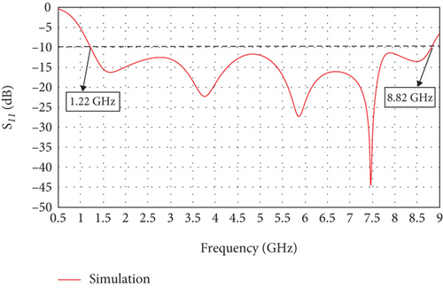
In the context of the rapid development of wireless body area network and ultra-wideband technology, this design puts forward a new structure of ultra-wideband flexible antenna. Its operating band is 1.22–8.82 GHz, with a maximum gain of 4.8 dBi. The antenna adopts a polyimide material with a relative dielectric constant of 3.5 and a thickness of 0.2 mm as the dielectric substrate. The overall size of the antenna is very small, measuring 0.15λ × 0.21λ at the lowest frequency of 1.22 GHz. In this paper, the influence of some antenna parameters on its performance, the influence of different bending conditions on the performance of the antenna, and the specific absorptivity of the antenna to the human body are discussed. In order to further explore the performance stability of the antenna, the performance of the antenna under right-angle bending is simulated and tested in this paper. Simulation results show that the antenna still has two frequency bands 1.22–2.58 GHz and 3.35–9.53 GHz under right-angle bending, which can still cover most of the commercial communication bands, and the measured results are in good agreement with the simulation results. Therefore, the antenna has strong adaptability and damage resistance and can be used in wearable equipment for military or emergency rescue.
1. Introduction
In recent years, with the rapid development of the fifth-generation mobile communication technology, the research related to the human body-centered wireless body area network (WBAN) [1] has attracted a lot of attention, and the wearable antenna, as an important part of the WBAN, has a wide range of applications in the military, biomedicine, and life and entertainment. Microstrip patch antennas have been widely studied because of their advantages of low profile, light weight, low cost, and easy to be conformal. Therefore, flexible microstrip patch antennas with various flexible materials such as paper [2], liquid crystalline polymer [3], and PDMS [4, 5] as the dielectric substrate have been investigated in a large number of ways, but like the traditional rigid patch antennas, flexible microstrip patch antennas also have the disadvantage of narrow bandwidth, which is the most important reason for restricting their applications.
Realizing antenna broadbanding can improve the communication quality and capacity of the system and reduce the radiation hazard to human body and environment. Therefore, to reach a large band is particularly important for the research of wearable antennas, various methods such as adding slotted structures [6], using fractal structures [7], changing the feed structure [8, 9], adding parasitic elements [10], and using defected ground structures (DGSs) [11, 12] have been reported to be effective in improving the bandwidth of microstrip patch antennas. For example, in [12], the authors present a flexible screen-printed antenna that utilizes a defective ground structure to increase the bandwidth. The relative bandwidth of the antenna was increased from 30% to 119% by adding DGS without increasing the size, with a wide measured bandwidth of 1.77–6.95 GHz. In addition, many studies have demonstrated that coplanar waveguide (CWP)–fed structures can also effectively improve the bandwidth and radiation directivity of the antenna [13, 14]. For example, in literature [14], the authors have proposed a circularly polarized antenna using CWP feed for the GPS and the final simulation results show that the relative bandwidth of the antenna is 123%.
The miniaturization is also the main direction of wearable antenna research, and conventional methods of antenna miniaturization include the use of high dielectric constant, geometric bending [15], surface slots [16], and shorting pins or probes [17–19]. However, these methods may degrade other properties of the antenna, such as increasing surface waves, changing radiation characteristics, and increasing losses. In addition, these methods achieve limited miniaturization and are complex and difficult to control. In contrast, fractal structures can be applied in the antenna design to achieve miniaturization of the antenna while avoiding the above problems.
Therefore, using fractal structure to design an antenna radiator can realize both antenna miniaturization and broadband. Fractal geometry has a self-similarity and space-filling effect, which can increase the electrical length of the antenna in a limited space, so as to achieve antenna miniaturization and broadband. A number of fractal antennas with good performance [20, 21] have been proposed. For example, an ultra-wideband monopole antenna based on a cardioid nested fractal structure with a bandwidth of 1.8–30 GHz has been proposed in the literature [22], but it has been designed on an FR-4 substrate, which is not suitable for wearable systems.
In this paper, a broadband flexible antenna based on nested fractal geometry is proposed. The antenna uses fractal geometry and a stepped CWP feed structure to increase the relative bandwidth of the antenna to 151.4%. The antenna has the advantages of simple structure, small size, low production cost, no over-hole and collector element, and so forth. The working bandwidth is 1.22–8.82 GHz, which can cover the commercial frequency bands of Bluetooth, WLAN, 4G, 5G, WiMAX, and so on. In addition, the antenna has good performance during various bending and fitting to the human body, which is basically the same as the flat state, making it ideal for wearable devices. The performance comparison between the proposed antenna and the antennas mentioned in the literature is shown in Table 1.
| Ref. | Total size L × W × H (mm 3) |
Substrate | Freq. range (GHz) | BW % | Flexible? |
|---|---|---|---|---|---|
| [3] | 50 × 42 × 0.1 | Rogers Ultralam3850 | 2.6–10 | 117.46% | No |
| [12] | 55 × 40 × 0.125 | Kapton | 1.77–6.95 | 119% | Yes |
| [14] | 55 × 55 × 1.6 | FR-4 | 1.12–4.72 | 123% | No |
| [20] | 30 × 17.6 × 1.6 | FR-4 | 2.9–10.7 | 115% | No |
| [22] | 47.5 × 35.1 × 1.58 | FR-4 | 1.8–30 | 178% | No |
| [23] | 42 × 40 | Polyester | 3.1–11.7 | 116% | Yes |
| Polyamide | 3.1–12.0 | 117% | |||
| Denim | 3.1–11.3 | 115% | |||
| Teslin | 2.9–11.8 | 121% | |||
| Proposed | 51 × 38 × 0.2 | Polyimide | 1.22–8.82 | 151.4% | Yes |
Compared with the literatures listed, the unique contribution of our work is to propose a new fractal structure in the design of a radiator structure which can significantly increase the bandwidth of the antenna. Secondly, we have simulated and tested the antenna under right-angled bend conditions, a condition not much explored in other literature. The results show that the antenna still maintains good broadband characteristics and usability. It proves that the antenna is highly adaptable and resistant to vandalism, making it suitable for use in emergency relief, military, and other situations that are prone to extreme conditions but where communication quality needs to be ensured.
2. Antenna Structure and Design Procedure
In this design, fractal geometry is applied to the design of the antenna radiator, and a new ultra-wideband fractal antenna is proposed, which utilizes the space-filling effect of fractal geometry to increase the electrical length of the antenna in a limited space, so as to realize the miniaturization and broadband of the antenna. The structural appearance of the antenna is shown in Figure 1, and the specific dimensions are shown in Table 2.
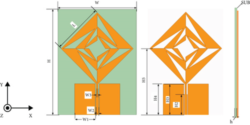
| Parameter | W | H | H2 | H3 | H4 | H5 |
|---|---|---|---|---|---|---|
| Value (mm) | 38 | 51 | 10 | 14.91 | 15 | 32 |
| Parameter | W1 | W2 | W3 | L | h | |
| Value(mm) | 10 | 1.4 | 0.75 | 24.7 | 0.2 |
The design of the radiator structure is inspired by the rose shape found in nature, which have layers of petals with fractal characteristics, as shown in Figure 2. For better growth and efficient utilization of space, flowers in nature exhibit distinct fractal patterns in their appearance. For antennas with limited space, in order to improve the efficiency of radiating and receiving electromagnetic waves, the space-filling effect of fractal geometry can be utilized to increase the length of the antenna within the limited space. As shown in Figure 3a, the first-order fractal principal radiator is formed by subtracting four identical triangles from a square. A triangle is a right triangle with an acute angle of 30°. On the basis of the first-order fractal, the horizontal flip shrinks by 0.62 times to form the second-order fractal, and so on. The antenna is fed by a tapering CWP to achieve better matching and to further broaden the impedance bandwidth. The antenna utilizes a 0.2-mm-thick flexible polyimide material as the dielectric substrate with a relative dielectric constant of 3.5 and a loss tangent of 0.008.


The simulation was performed using ANSYS High-Frequency Simulation Software (HFSS) (version 21).
- 1.
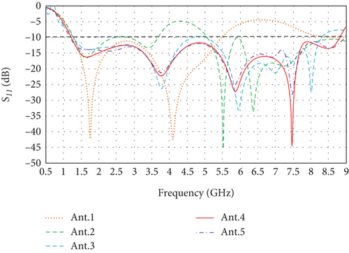
Ant. 1 is a reference antenna with a radiating patch structure in the form of a square rotated by 45°, which operates with a bandwidth of 1.4–5.80 GHz.
- 2.
Ant. 2 is a first-order fractal formed by subtracting four hollow triangles from Ant.1. The subtracted triangles are right triangles with an angle of 30°. The feed structure of the antenna is improved to obtain a better matching effect. From the figure, it can be seen that Ant. 2 generates a new frequency band in the high frequency part, but the effect is not very good in the low frequency part.
- 3.
Ant. 3 is a second-order fractal iterative structure of the radiator, and it can be seen from the Figure 4 that the second-order fractal also produces better bands in the low-frequency part. However, the impedance matching at 4.5–5 GHz is not very good and the antenna is a two-band broadband form at −10 dB criterion.
- 4.
Ant. 4 is the third-order iterative form of the radiator, and the S11 results show that the antenna is an ultra-broadband form with an operating bandwidth of 1.22–8.82 GHz at the third-order iteration. This is due to the fact that the internal resonant branching of the fractal structure generates more center frequency and extends the bandwidth through the asymptotic structure.
- 5.
Ant. 5 is the fourth-order iterative form of the radiator, and it can be seen from the Figure 4 that the S11 plots of the fourth-order and third-order iterations basically overlap and do not produce better S11 plots, so the antenna chooses Ant.4 as the final form of the antenna’s radiator.
3. Results and Discussion
3.1. Simulation Results
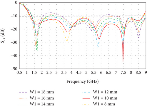
The antenna uses a CWP feed. This feeding mode can effectively increase the antenna bandwidth. Therefore, the antenna grounding surface width W1 is analyzed by parameter scanning as shown in Figure 5, from which it can be seen that the broadband performance of the antenna gradually becomes better with the gradual decrease of the width of the grounding surface, and the widest bandwidth and the best matching effect appear when W1 is 10 mm. Therefore, the ground plane width W1 is selected as 10 mm.
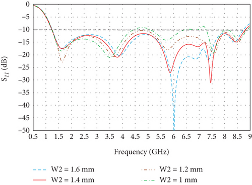
The antenna has a 50-Ω CPW feedline, and the impedance variation method can be utilized to achieve a good match between the impedance of the radiator and the feed port, thus extending the bandwidth to a certain extent. As shown in Figure 6, the reflection coefficient of different feed lengths w2 is plotted. From which it can be seen that when w2 is 1.4 mm, the reflection coefficient is optimal. It can be seen from the figure that when w2 = 1 mm and 1.2 mm, the impedance matching effect of the antenna at the high frequency is poor, and the antenna is not a broadband. When w2 = 1.6 mm, the reflection coefficient at the 6-GHz frequency point is too small, affecting the overall effect. Therefore, w2 = 1.4 mm is selected for comprehensive consideration.
The simulated S11 of the proposed antenna is shown in Figure 7. The results show that the impedance bandwidth of the antenna (S11 < −10 dB) is 1.22–8.82 GHz, with a relative bandwidth of 151.4%. As shown in Table 3, the antenna can cover most commercial frequency bands.
| Bandwidth (simulation) | Covered commercial bands |
|---|---|
| 1.22–8.82 GHz (151.4%) |
|
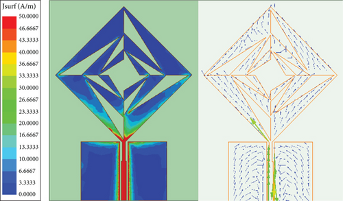
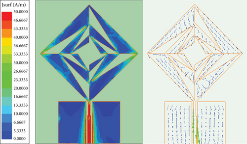
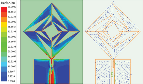
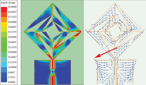
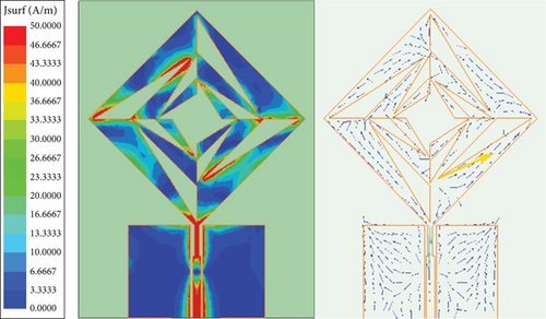
The antenna current distribution and vector distribution at each center frequency point are shown in Figures 8a, 8b, 8c, 8d, and 8e. It can be seen that at 1.66 GHZ, the antenna current is mainly concentrated in the feedline and the lower part of the antenna, and there is almost no current in the upper part of the antenna. At 3.76 and 5.86 GHz, the currents are mainly distributed on the first-order iterative structure, and the internal iterative currents are less distributed. At 7.46 and 8.5 GHz, the current distribution on the antenna is more uniform and concentrated in the corners.
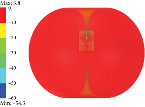
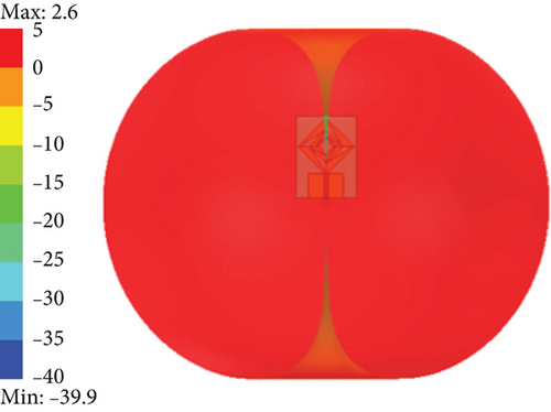
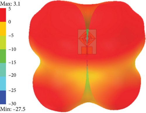
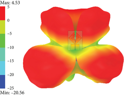
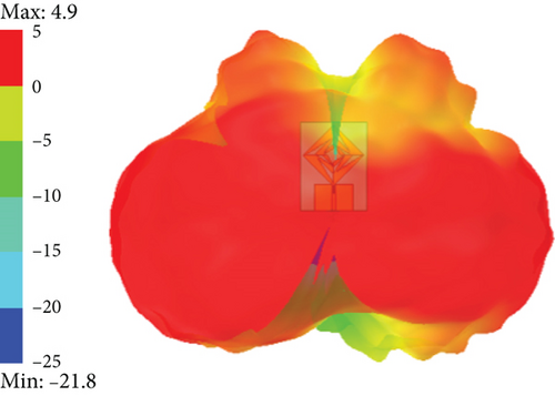
The simulated 3D far-field radiation direction diagram of the propose antenna is shown in Figure 9. The antenna exhibits good omnidirectionality at the two low-frequency resonance points of 1.66 and 3.76 GHz, and the directionality of the antenna gradually increases as the frequency increases. The maximum gain of the antenna at each center frequency point are −3.8 dBi, 2.6 dBi, 3.1 dBi, 4.2 dBi, and 4.8 dBi, respectively. The antenna has a good radiation performance at each frequency point.
3.2. The Simulation of Bending
In order to further verify the applicability of the antenna to wearable devices, the bending of the antenna around a cylinder of radius R along the x-axis and y-axis is simulated in HFSS. The bending radii are 30 mm, 45 mm, and 90 mm. In addition, the antenna is further simulated in the case of right-angle bending and wave bending, in order to explore the stability of the antenna performance in the special bending case. The bending state is shown in Figure 10.


Figure 11a is the S11 plot of the antenna bent along the y-axis, from which it can be seen that the S11 curve of the antenna bent along the y-axis is basically overlapped with the simulated S11 curve, and the frequency point is only slightly shifted to the left, which proves that the bending along the y-axis has very little effect on the performance of the antenna. Figure 11b is the S11 plot of the antenna bent along the x-axis, the antenna’s center frequency point is shifted to the left a little and the broadband is also reduced by about 0.5 GHz, but the overall effect is still good. Figure 11c for the antenna bent at right angles and wavy bending, the S11 curve of the wavy bending maintains good agreement with that of the flat state, and the S11 value is reduced by about 20 dB only at the frequency point of 7.5 GHz. The antenna in the case of the right-angle bending is transformed from an ultra-broadband to a multi-band in the −10 dB criterion, multiband in three bands, but still has excellent usability. Therefore, the antenna has good conformality.
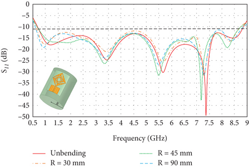
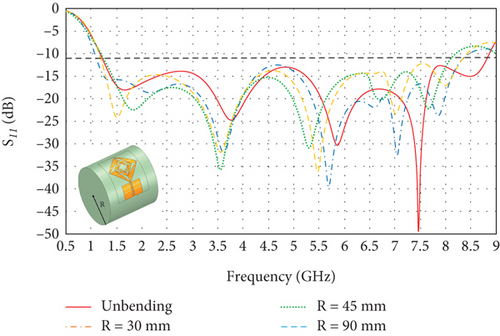
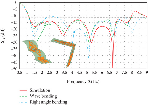
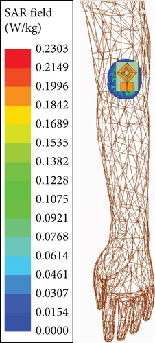
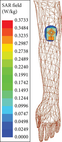
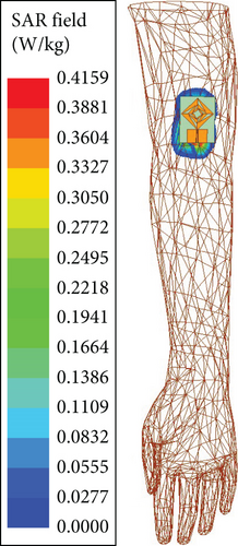
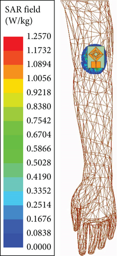
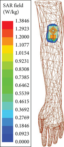
Figure 12 show the specific absorption rate (SAR) values at each center frequency point for the human arm model. Simulation of SAR values is performed using the human structure model available in the HFSS Component Library (version 21). Simulation results show the antenna has a SAR value of 0.2303 W/kg at 1.66 GHz, 0.3733 W/kg at 3.96 GHz, 0.4159 W/kg at 5.96 GHz, 1.2570 W/kg at 7.46 GHz, and 1.3846 W/kg at 8.5 GHz. Although SAR values are increasing with frequency, they are below international standards of human SAR < 1.6 W/kg.
4. Fabrication and Measurement Results
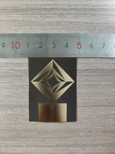
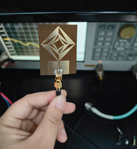
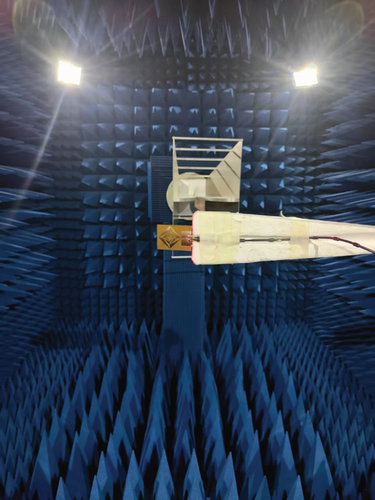
In order to test the accuracy of the actual performance of the antenna, a prototype of the antenna was built. The dielectric plate of the antenna is made of polyimide with dimensions 51 × 38 × 0.2 mm3 as shown in Figure 13a. The S11 diagram of the antenna was tested with a vector network analyzer (Agilent E5071B), which has a maximum test frequency of 8.5 GHz, as shown in Figure 13b. A microwave electromagnetic anechoic chamber is used to measure the 3D radiation direction map, gain, and efficiency of the antenna as shown in Figure 13c.
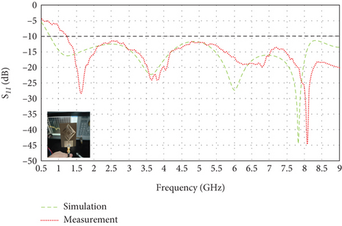
As shown in Figure 14, compared with the simulation data, the frequency band of the proposed antenna in the measured state shifts to the right as a whole, and the initial frequency of the frequency band under the −10 dB standard changes from 1.22 to 1.66 GHz. This may be due to the introduction of additional metal during the soldering process, which alters the electrical length and matching characteristics of the antenna, or due to a problem in the production process of the dielectric substrate that causes the permittivity of each batch of PI to float within a range that is different from the value of the permittivity of the polyimide in the HFSS library of materials used in the simulation.
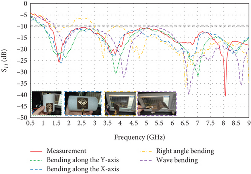
Since the proposed antenna is a wearable antenna, it is necessary to analyze the stability of its performance during bending as various bends inevitably occur during the wearing process. Figure 15 shows the comparison of the bent antenna with the S11 of the flat antenna. Various bending situations that may occur during wearing of the antenna are considered, including transverse bending, longitudinal bending, wavy bending, and right-angle bending. From the figure, it can be seen that the bandwidth of the antenna is basically the same as those in the flat state when bending along the x-axis, bending along the y-axis, and wavy bending. In the extreme bending case of right-angle bending, the antenna changes to two bands, 1.68–2.49GHz and 3.17–8.5GHz, but still covers many commonly used commercial bands, so the antenna’s performance is very stable under all kinds of bending conditions.
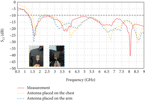
A comparison of the S11 values when the antenna is placed on different parts of the human body is shown in Figure 16. It can be seen from the figure that there is not much effect in terms of bandwidth, except that the center frequency point is shifted to the right. This shows that the antenna does not have a significant impact on the performance due to the co-conformity with the human body, which further proves that the performance of the proposed antenna is highly stable, in compliance with design requirements.
The 3D radiation direction diagrams of the antenna at each central frequency points are shown in Figure 17. It can be seen from that the antenna as a whole tends to be omnidirectional radiation.
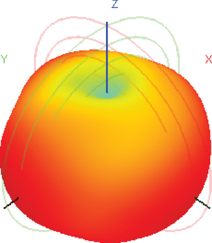
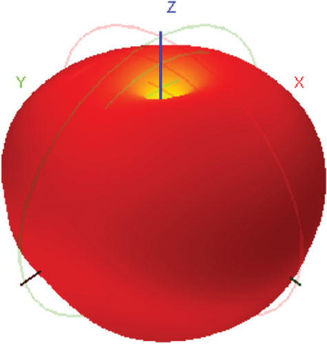
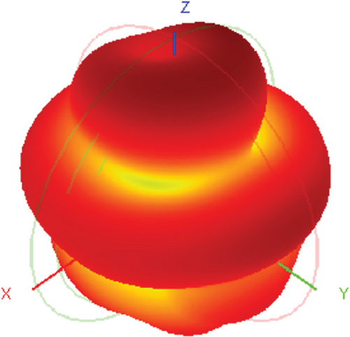
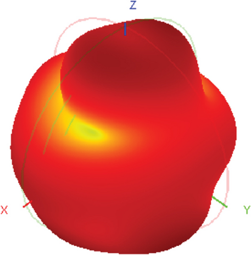
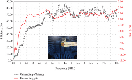
Figure 18 shows the antenna efficiency and gain curves measured through the anechoic chamber, where the red line is the measured gain curve of the antenna and the black line is the measured efficiency curve of the antenna. From the figure, it can be seen that the antenna’s gain ranges from 1.14 to 4.82 dBi and the efficiency ranges from 48.81% to 85.06% in the whole-frequency band range. As a result, the antenna prototype has good efficiency and high gain over the entire frequency band range and can be widely used in mobile communication terminals. However, when testing the antenna directional map in an anechoic chamber, the antenna inevitably needs to be connected to the test equipment through RF cables and connectors. These RF cables and connectors are very close to the antenna, and their radiation can affect the antenna test to the extent that there is a slight band fluctuation.
5. Conclusion
In this design, a novel ultra-wideband fractal antenna with flower-like structure is proposed, with an antenna bandwidth range of 1.22–8.82GHz, a relative bandwidth of 151.4%, and a maximum gain of 4.8 dBi. The test results show that the antenna has good performance in various bending states and in the case of co-conformity with the human body. Overall, the antenna proposed in this paper is characterized by small size, light weight, and stable performance and realizes the ultra-wideband characteristics of the antenna in a simple way. Therefore, it is very suitable for wearable devices in extreme environments such as military and emergency rescue and has strong engineering applicability.
Conflicts of Interest
The authors declare no conflicts of interest.
Funding
This work was supported in part by the S&T Program of Hebei (No. 23375402D) and the Natural Science Foundation of Hebei Province (No. F2021508009).
Open Research
Data Availability Statement
The simulation and test data used to support the findings of this study are included within the figure files.


