Manifold Frequency Division Multiplexer With Narrowband SIW–SSPP Hybrid Filters
Abstract
A manifold-coupled multiplexer comprising substrate integrated waveguide (SIW)–spoof surface plasmon polariton (SSPP) hybrid filters and a microstrip line network is proposed for Ka-band applications, achieving a compact profile and low insertion loss. The narrowband hybrid filter is designed by converging the cut-off frequencies of SIWs and SSPPs, which may avoid the high-order modes of the resonant filters, and two SSPP slots are chosen for filter miniaturization without significantly sacrificing the cut-off response. A short taper is designed to connect the hybrid filter and microstrip lines, and the microstrip line network is carefully optimized to match the manifold phase configuration with a compact size. A prototype is fabricated and characterized for demonstration. The experimental insertion loss is 2.10, 2.49, and 2.61 dB at 28.2, 29.7, and 31.2 GHz, respectively, and the corresponding 3 dB bandwidth is 4.1%, 4.7%, and 4.8%, respectively, showing a good match with the simulation. The reflection loss is larger than 10 dB from 27.8 to 31.4 GHz. Considering the promising out-of-band rejection of the hybrid filters, such a configuration should be suitable for multiplexers with large channel numbers and may find many applications in ultra-wideband and multifunctional communication systems.
1. Introduction
As the development of the fifth generation (5G) mobile communication, Ka-band has gained great interest in many important applications [1], such as base station transceivers [2], satellite communication [3], continuous-wave monostatic radar [4], and deep-space data transmission [5]. Frequency division multiplexing (FDM) is important in these advanced systems to obtain multichannel functionalities and high spectral efficiency, which can be used either as a channel divider or channel combiner [6]. Typically, FDM has four kinds of configurations including hybrid-coupled, circulator-coupled, directional-filter, and manifold-coupled types [7]. Wherein hybrid-coupled multiplexers have large size and require precise machining, circulator-coupled ones suffer from extra loss and high cost, and the directional-filter approach is limited to narrowband applications. In regard to low insertion loss and good electromagnetic compatibility, manifold-coupled FDM is typically considered a promising choice [7–10]. However, most of the manifold-coupled multiplexers are designed in metallic waveguides with bulky profile, large weight, and high cost [11–15]. To achieve miniaturization, ridged substrate integrated waveguides (SIWs) have been investigated for multiplexing at the cost of considerable fabrication complexity [16].
Recently, SIW–spoof surface plasmon polariton (SSPP) hybrid filters have gained great interest by combining the low cut-off response of SIWs and the high cut-off response of SSPPs [17–19]. Due to the cut-off responses, such hybrid filters address broadband out-of-band rejection, which is preferable for FDMs. However, their 3 dB bandwidth is typically larger than 13% [20, 21]. To the best knowledge of the authors, SIW–SSPP hybrid filters have not been applied in FDM.
In our previous work, a novel SIW–SSPP hybrid filter with a narrow bandwidth and microstrip line (MSL) feed has been proposed [21], achieving a 3-dB bandwidth of 3%. In this paper, a manifold-coupled FDM comprising three SIW–SSPP hybrid filters at 28.2, 29.7, and 31.2 GHz is proposed for the first time. Low-loss and compact MSL manifolds are designed to connect the three filter units with phase delay match. The proposed manifold-coupled multiplexer achieves a 3-dB passband of 4.1%, 4.7%, and 4.8% and an insertion loss of 2.10, 2.49, and 2.61 dB at 28.2, 29.7, and 31.2 GHz, respectively, with the benefit of ultrawideband out-of-band rejection, showing good consistency with the simulation.
2. Design and Simulation
Ansys high frequency structure simulator (HFSS) is employed to design the following filters and FDM on a 10-mil thick Rogers 5880 substrate. The substrate has a low loss tangent of 0.0009 and a relative permittivity of 2.2, and the laminated copper layer has a thickness of 18 μm. As aforementioned, SIWs and SSPPs exhibit low and high cut-off responses, respectively, which could be combined for the band-pass function. Typically, complementary SSPPs, that is, periodic rectangular slots, are designed on the SIW broadside to get a high cut-off frequency. However, simple rectangular slots are not long enough to get a narrow passband.
2.1. Filter Design
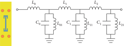
Figure 1 illustrates the proposed SIW–SSPP hybrid filter with I-shaped SSPP slots, which exhibits much larger effective length and thus achieves a much lower cut-off frequency. As a bandpass filter, the equivalent circuit model of a SIW unit with I-shaped slot is depicted in Figure 1c. Three parallel L-C resonators are cascaded in series, where L0, L1, and L2 are the series inductances along the SIW signal propagation direction. C0, C1, and C2 are the capacitances induced by the lengths Lspp, Lspp1, and Lspp2 in the I-shaped slot, respectively, and L01, L11, and L21 are the corresponding shunt inductances.
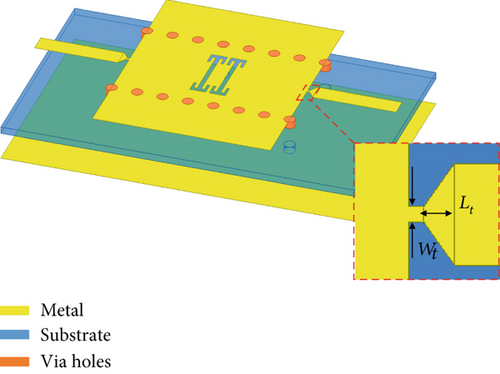
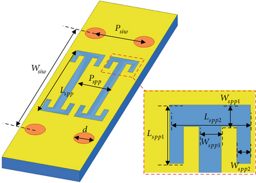
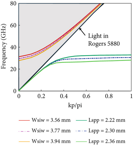
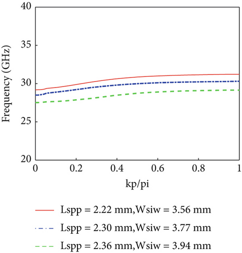
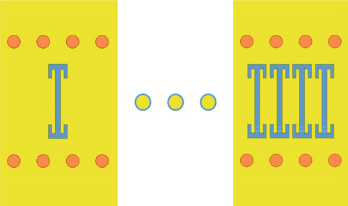
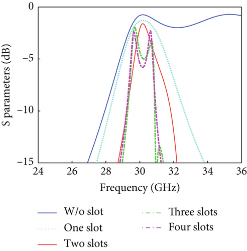
To precisely obtain the cut-off frequencies, eigenmode simulation is performed for SIW and SSPP, which are depicted as the inserts in Figure 2. Sweeping Wsiw and Lspp can efficiently tune the cut-off frequencies of SIWs and SSPPs, respectively, as shown in Figure 2a. Based on this analysis, three hybrid filters with MSLs feeding are designed at 28.2, 29.7, and 31.2 GHz. The MSLs are suitable for the design of complex and compact manifold networks. To input and output signals, a short taper is designed to connect SIW with large impedance and 50-Ω MSL for low insertion loss and compact profile, which has been widely used for MSL-based interdigital and comb-line filters [22]. The dispersion relations of the three filters are shown in Figure 2b, whose dimensions are depicted in Table 1. To investigate the cut-off response induced by the SSPP slots, hybrid filters with the same size consisting of different numbers of slots are simulated, whose S-parameters are shown in Figure 3. It can be seen that the out-of-band rejection becomes sharper, and the insertion loss increases, as the slot number increases. To compensate for the bandwidth and insertion loss, the slot number is chosen as two. In this case, the insertion loss is 1.82, 1.89, and 2.06 dB at 28.2, 29.7, and 31.2 GHz, respectively, and the 3-dB bandwidth is 4.1%, 3.9%, and 3.5%, respectively.
| Wsiw(f1) | Wsiw(f2) | Wsiw(f3) | d | Psiw |
|---|---|---|---|---|
| 3.77 mm | 3.94 mm | 3.56 mm | 0.4 mm | 0.91 mm |
| Lspp(f1) | Lspp(f2) | Lspp(f3) | Wspp1 | Wspp2 |
| 2.3 mm | 2.36 mm | 2.22 mm | 0.16 mm | 0.10 mm |
| Lspp1(f1) | Lspp1(f2) | Lspp1(f3) | Lspp2 | Pspp |
| 0.51 mm | 0.4 mm | 0.38 mm | 0.58 mm | 0.70 mm |
| Wt | Lt | |||
| 0.1 mm | 0.2 mm |
2.2. FDM Unit Design
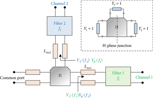
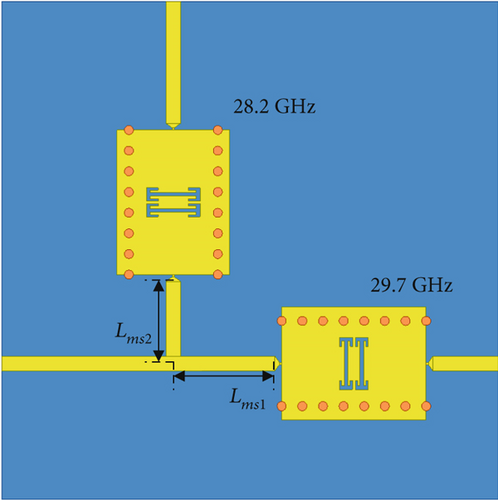
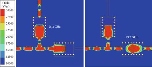
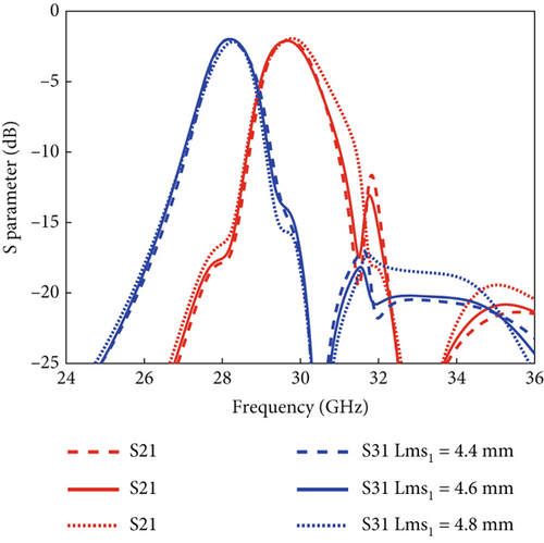
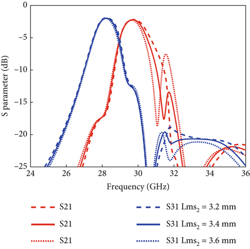
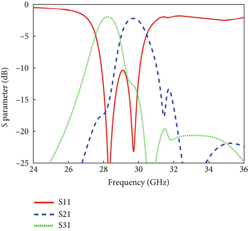
Due to the phase error induced by the transitions of the filters, such as the short tapers, the distributed manifold arms should be optimized. The pitches between the T-junction and filters, that is, Lms1 and Lms2, are investigated in Figure 5a,5b. Due to the shift of the transmission zero, the passband of S21 becomes a little wider as Lms1 increases and gets narrow as Lms2 increases. In contrast, it shows little impact on S31. This phenomenon reveals that the end-fed filter is more sensitive to the pitch variation. Finally, Lms1 = 4.6 mm and Lms2 = 3.4 mm are chosen to optimize the bandwidth and out-of-band rejection, whose S-parameters are illustrated in Figure 5c. The return loss is less than −10 dB from 27.8 to 30.1 GHz, the insertion loss is 1.96 and 2.2 dB at 28.2 and 29.7 GHz, respectively, and the corresponding passbands have a 3-dB bandwidth of 4.85% and 5.15%, respectively. In this case, the insertion loss of the manifold is 0.14 and 0.31 dB at 28.2 and 29.7 GHz, respectively, which is mainly due to the conductive and radiation losses of the MSLs and is not significant with respect to the total loss. Figure 4c shows the simulated electric field distributions at 28.2 and 29.7 GHz, revealing good spectral division and weak parasitic coupling at different output ports. The dimensions of the proposed dual-channel FDM are as small as 2.07 λ × 2.07λ at 28.2 GHz and 2.17λ × 2.17λ at 29.7 GHz.
2.3. Three-Channel FDM Design
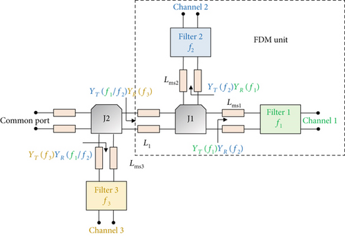
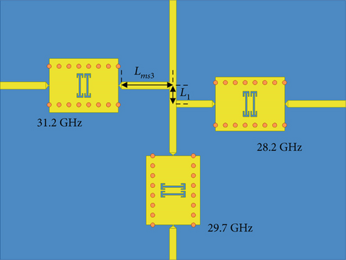
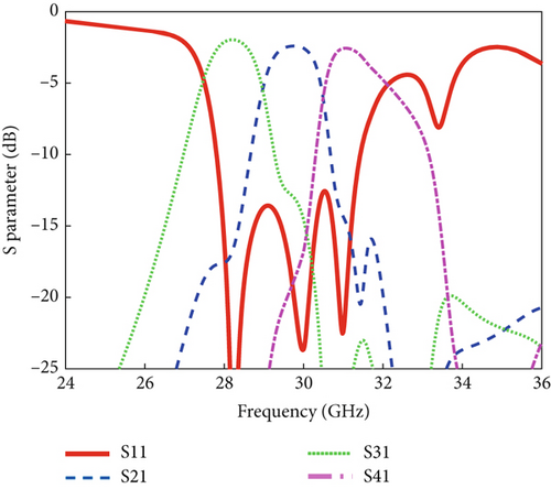
To show the diversity of the proposed techniques, a three-channel frequency division multiplexer is designed in this section. Figure 6a shows the configuration of the manifold multiplexer consisting of two T-junctions and three filters, and Figure 6b illustrates the proposed FDM with SIW–SSPP hybrid filters 28.2, 29.7, and 31.2 GHz. For simplification, the dual-channel FDM can be considered as an end-fed filter. Similarly, ZT (f3) = 50 Ω and ZR (f1/f2) = ∞ in channel 3, and ZT (f3) = ∞ and ZT (f1/f2) = 50 Ω at the common port of Channels 1 and 2. In this case, Lms3 and L1 should be optimized as discussed in the last subsection. First, Lms3 and L1 are chosen as 5λF3/4 and λF3/4, respectively, to minimize the device profile. Then, Lms3 and L1 are slightly swept to obtain a good phase match and low reflection. Lms3 and L1 are optimized as 4.54 and 1.7 mm, respectively. The S-parameters of the three-channel FDM with optimization are shown in Figure 6c. The three passbands are centered at 28.2, 29.7, and 31.2 GHz, respectively, and the corresponding 3-dB bandwidth of the passbands is 5.10%, 4.68%, and 4.68%, respectively. The insertion loss is 1.95, 2.42, and 2.54 dB at 28.2, 29.7, and 31.2 GHz, respectively, and the loss induced by the manifolds is 0.14, 0.53, and 0.48 dB for each channel, respectively. Figure 7 shows its simulated electric field distributions and good spectral division. The size of the proposed three-channel FDM is just 2.4λ × 3.2λ at 29.7 GHz. The proposed FDM shows good electromagnetic compatibility due to the SIWs and potential for large channel numbers due to the nonresonant function of the hybrid filters.

3. Experiment and Results
A prototype was fabricated with the optimized dimensions in Table 1, as shown in Figure 8a. Long MSLs are designed to provide enough space for integrating end-launch connectors. Figure 8b illustrates the measurement system set-up. The three-channel FDM is integrated with four end-launch connectors from Southwest Microwave Inc. Two ports are connected to a vector network analyzer (VNA) Ceyear 3672E for passband characterization, and the other two ports are integrated with 50-Ω loads to minimize the reflection. The insertion loss of the connector is about 3 dB at 30 GHz. Before measurement, the VNA was calibrated with the calibration kit 85058E using the standard short-load-open-through (SLOT) method.
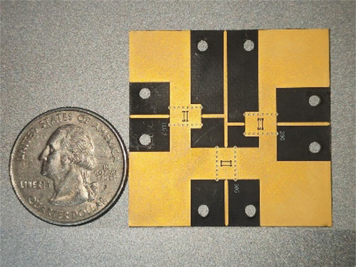
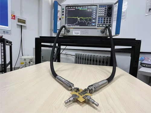
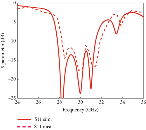
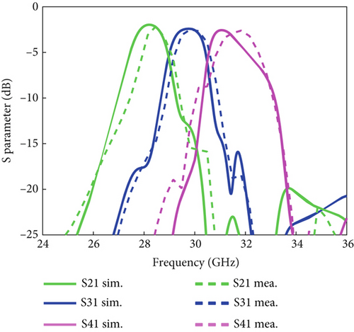
Figure 8c,d shows the measured S-parameters of the proposed FDM, which are in good agreement with the simulated data. The reflectivity is less than −10 dB from 27.8 to 31.4 GHz, and the absolute insertion loss is about 2.10, 2.49, and 2.61 dB at 28.2, 29.7, and 31.2 GHz, respectively, which are calculated by excluding the connector loss. The 3-dB bandwidth of the three channels is 4.1%, 4.7%, and 4.8% at 28.2, 29.7, and 31.2 GHz, respectively. Table 2 compares the proposed manifold-coupled FDM with other reported devices [8–16]. It should be noted that the proposed FDM addresses small profile, low insertion loss, and ease of fabrication.
| Ref. | Freq. (GHz) | IL (dB) | FDM type | Filter structure | Manifold structure | Channel NO. | Length × width/λ |
|---|---|---|---|---|---|---|---|
| [8] | 410–490 | 1.72–2.63 | Hybrid | Waveguide | Waveguide | 3 | ~26.67 × 26.67 |
| [9] | 19–20 | ~8.8 | Circulator | Waveguide | Waveguide | 8 | ~22.10 × 11.05 |
| [10] | 2.2–2.8 | 3.26–3.8 | Directional Filter | MSLs | MSLs | 4 | ~1.43 × 0.63 |
| [12] | 200–225 | ~1.7 | Manifold | Waveguide | Waveguide | 4 | ~13.33 × 26.67 |
| [13] | 125–156 | 0.54–0.62 | Manifold | Waveguide | Waveguide | 3 | ~52.8 × 52.8 |
| [14] | 9.5–10.7 | 1.22–2.11 | Manifold | Waveguide | Waveguide | 5 | Not available |
| [15] | 17.2–17.8 | ~2 | Manifold | Waveguide | Waveguide | 12 | 20.65 × 12.72 |
| [16] | 220–330 | 3–7 | Manifold | Ridged SIW | Ridged SIW | 3 | ~4 × 5 |
| This work | 28–31 | 2.10–2.61 | Manifold | SIW–SSPP | MSLs | 3 | ~2.4 × 3.2 |
4. Conclusion
In sum, a Ka-band FDM with SIW–SSPP hybrid filters is demonstrated with a compact profile, low insertion loss, and good out-of-band rejection. Theoretical analysis and simulation of the manifold FDMs are discussed. Dual-channel and three-channel FDMs have been investigated at 28.2, 29.7, and 31.2 GHz, whose insertion loss is less than 2.61 dB in each channel. The proposed approach is suitable for compact multichannel FDM at millimeter wave frequencies.
Conflicts of Interest
The authors declare no conflicts of interest.
Author Contributions
Y.W. and Z.L. contributed equally to this work.
Funding
This research is supported by the National Key Research and Development Program of China (10.13039/501100012166) (2022YFA1400025), the National Natural Science Foundation of China (10.13039/501100001809) (62371272), the Shandong Provincial Natural Science Foundation (ZR2023ZD08, ZR2024LLZ006), and the Key Technology Program of Qingdao City (23-1-2-qljh-5-gx).
Acknowledgments
This work was supported by the National Key Research and Development Program of China (2022YFA1400025), the National Natural Science Foundation of China (62371272), the Shandong Provincial Natural Science Foundation (ZR2023ZD08, ZR2024LLZ006), and the Key Technology Program of Qingdao City (23-1-2-qljh-5-gx).
Open Research
Data Availability Statement
The data that support the findings of this study are available from the corresponding authors upon reasonable request.


