Performance Evaluation of Wideband Dual Port Octagonal-Shaped Millimeter-Wave MIMO Antenna for Satellite Communication
Abstract
A printed MIMO antenna specifically designed for small satellite communication has been presented in this paper. The antenna is invented of two radiators resonating at millimeter-wave and constructed using Rogers’s RT duroid 5880. The design includes two identical octagonal patches with a diamond-shaped slot and having two quadrilateral notches. These elements are placed over a substrate and connected to a microstrip transmission line that embeds a quarter-wave transformer. To establish the effectiveness of the MIMO antenna being proposed, a comparative analysis is conducted between its simulated and experimental performance. Each radiator in the antenna setup includes partial ground, which forms the back layer of the substrate. The design is simulated on the CST tool, and measurements are conducted on a Rohde and Schwarz vector network analyzer. The obtained results show a favorable level of agreement with the simulated outcomes, validating the effectiveness of the proposed MIMO antenna. The antenna design offers exceptional features such as wide bandwidth, self-isolated, high gain, and a directional radiation pattern while also supporting a wide frequency band, making it an ideal choice for 28 GHz band applications. The performance of MIMO antennas in diversity can be determined using parameters such as envelope correlation coefficient (ECC), diversity gain (DG), and total active reflection coefficient (TARC). Satellite communication will be improved by implementing the suggested MIMO antenna through upgrading small satellite communication systems.
1. Introduction
The popularity of the fifth generation (5G) network development, which aims at accommodating innovations such as faster wireless broadband access and IoT, is increasing. However, this terrestrial connectivity upgrade has not been limited to that goal alone, as it is expected to affect also satellite communication systems. The major advantage of 5G is its ability to operate at higher frequency bands, including millimeter-wave (mm-wave) wavelengths, which could not be used for mobile communications earlier [1]. Therefore, one has to consider free space loss, which becomes more evident with an increase in frequency and distance. For these reasons, mm-wave frequencies are badly affected by this phenomenon, with even short distances causing a substantial drop in signal strength. This effect is more evident at mm-wave frequencies, where even small distances can lead to a great decrease in the signal strength [2]. Thus, obstructions within line-of-sight may disrupt communication links and underutilize some particular frequencies [3]. Meanwhile, recent studies have attempted to address these limitations by investigating the possibility of incorporating mm-wave bands into 5G mobile communication systems and thereby suggesting their use for various wireless applications in the 5G era [4]. Moreover, if satellite communication is to be completed faster and with more reliable data transfers, this would increase the speed of data transfer and lower latency, thus improving the capacity of satellite networks in deploying 5G technologies [5]. As shown in Figure 1, the dynamics of satellite communication networks portray a unique communication configuration. Satellite communication does away with intermediaries, and users can send signals directly to satellites. Good examples of direct satellite communications are satellite phones and television systems. On the other hand, indirect satellite communication involves sending signals from a user terminal to a ground station and then relaying them to a satellite. These signals are then taken up by satellites and passed down to yet another ground station that channels them towards an intended receiver. Satellite internet networks often depend on indirect communication mechanisms. By looking through the performance of 5G technologies in satellite communication, we can get new insights and open up possibilities for increased connectivity and efficiency in terrestrial and satellite networks. Satellite communications systems play a major role in linking sparse areas with no usual communication infrastructure. 5G will usher in greater satellite communication optimization, resulting in quicker, more dependable connections to these places. 5G terrestrial networks can create an integrated communications ecosystem. Consequently, this unification might enhance reliability, decrease latency, and enable more efficient communication practices. The rise of the 5G network will surely revolutionize technology in satellite communications. With better access to rural locations and a more unified communications ecosystem, 5G will improve capacity, speed, and reliability. MIMO antennas are effective in small satellite communication systems since they help enhance data throughput and improve signal quality. Multiple antennas are used at both the transmitter and receiver sides in MIMO techniques, thereby strengthening the communication links. MIMO systems can make use of the multipath—a phenomenon where a signal bounces off various surfaces and takes different paths to reach the receiver. The use of multiple antennas allows MIMO to combine the different signal paths for better signal quality. Besides, in small satellite communication systems using MIMO antennas, the fading and interference due to the movement of the satellite or the Earth’s atmosphere can be reduced. The fading and interference caused by the movement of the satellite or the Earth’s atmosphere in small satellite communication systems that use MIMO antennas can be reduced. MIMO antennas may also bring some diversity in the communication channel, which is very important for dependable communication when the signals are degraded for some reasons, such as interference or fading. Therefore, the MIMO antennas for small satellite communication systems must be planned considering the exclusive system requirements for these applications, including frequency range, power requirements, and any restrictions on placement on the satellite or the communication range. In satellite communication, for MIMO antennas, the antennas have to be compact, lightweight, low profile, and with high gain and efficiency to maximize the coverage area and reduce the transmitted power. There are many different types of antennas used for MIMO systems for small satellite communications, including patch antennas, microstrip antennas, and array antennas, each with its advantages and disadvantages [6]. The 28 GHz band boasts significant implications among the prospective band spectrums for mm-wave uses in the future because of its poor absorption rate and accessibility of an extensive unlicensed band by enabling seamless integration between satellite and spectrum. These antenna designs cater to various devices such as smartphones, portable devices, dongle gadgets, and smartwatches. Numerous studies and reports have been dedicated to constructing antennas optimized for the 28 GHz frequency band [7–9]. This collective effort reflects the recognition of the importance of enabling efficient and effective communication at mm-wave frequencies, particularly within the specified frequency range.

Numerous antennas operate in 28 GHz frequency bands that have been reported [10–17].
A flexible wideband antenna with high gain working throughout the range of 27.3–34.9 GHz [10] and a severed sensor that is 5G compliant for IoT and a complementary metal oxide semiconductor (CMOS) die antenna functioning at 28 and 60 GHz have been reported in 2020 [11]. A small, circularly polarized 28 GHz antenna that can be used for device-to-device (D2D) communication was developed and evaluated [12]. An antenna array for satellite systems that are tuned to resonate across many frequency bands covering mm-waves was demonstrated in [13]. In [14], a codesigned mm-wave antenna operating between 25 and 30 GHz is presented, along with LTE antennas operating between 700 and 960 MHz and 1710 and 2690 MHz. A planar helix antenna operating between 26.25 and 30.14 GHz frequency was described in [15]. It has a 5.83 dB gain and more than 85% radiation efficiency. This innovative transparent antenna design boasts an impressive bandwidth of 3.624 GHz, operating seamlessly within 26.369–29.993 GHz [16]. According to [17], a wideband antenna design using Rogers RT Duroid 5880 material is working at a frequency of 28 GHz. It is clear from the aforementioned literature that the mm-wave spectrum has several uses in contemporary IOT and 5G operations.
To deal with atmospheric attenuation and path loss problems in the mm-wave spectrum, antenna systems with high gain are essential for next-generation wireless systems. Thus, the article demonstrates a simple two-element octagonal patch that serves as a MIMO antenna that has been designed using the microstrip method to resonate at 28 GHz with high radiation efficiency while maintaining reasonable gain and wide bandwidth.
- •
The antenna has exceptional wideband coverage, making it versatile and adaptable across multiple frequency ranges.
- •
Our antenna has a wide tuning range, allowing for flexible adaptation to various working situations.
- •
A major emphasis in our work is on cost-effectiveness without compromising performance. The proposed antenna offers an affordable solution, addressing the economic considerations of deployment.
The article is structured as follows. Section 1 addresses the significance of 5G and satellite communication in the modern day, the assigned frequency bands, and numerous antennas mentioned in the literature at the mm-wave frequency range. Reports on the geometrical representation and single antenna design procedure are illustrated in Section 2. Section 3 evaluates the performance traits of a two-element MIMO antenna with comparisons using simulated and measured outcomes. The conclusion is covered in Section 4.
2. Design Configuration of Single Antenna
This section discusses the process of designing and simulating an octagonal-shaped antenna with a partial ground configuration operating at 25–35 GHz. The specific frequency band being targeted for this antenna design is 28 GHz. To achieve this, the dimensions of the antenna (15.5 × 18 × 1.6 mm3) belong to the Rogers family. This substrate possesses a dielectric constant of 2.2 and a loss tangent of 0.0009, both of which are important parameters for the antenna’s performance. The antenna configuration entails a fundamental rectangular patch with a quarter-wave transformer (QWT) that is connected by a microstrip transmission line. The main aim is to attain impedance matching utilizing both the transmission line and quarter-wavelength approaches, facilitating effective power transmission between the feed line and the antenna structure. Through iterative modifications to the antenna’s dimensions and parameters, the objective is to establish harmonized impedance across the desired frequency band. This optimization process enables the maximization of power transfer and guarantees efficient antenna performance within the 25–35 GHz frequency range. To achieve this, simple rectangular patch antenna design algorithms from references [14, 18] have been taken into consideration, and comprehensive analytical expressions have been demonstrated.
Here, the extended length is ΔL, the thickness of the dielectric material is h, W is the width of the patch and εreff is the effective dielectric constant.
For W ≫ λ0.
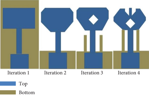
The antenna is optimized to get the desired band of 28 GHz, which is offered in four iterations as demonstrated in Figure 2. The geometrical symbols and single antenna design configuration are depicted in Figure 3. Table 1 provides detailed optimized parametric measurements of a single antenna. In a single antenna, the comparative outcomes of the reflection coefficient (S11) for all iterations are presented in Figure 4. This was accomplished by structuring a thorough investigation to comprehend the behaviour of the width, length, and position of each slot and stub on a patch.
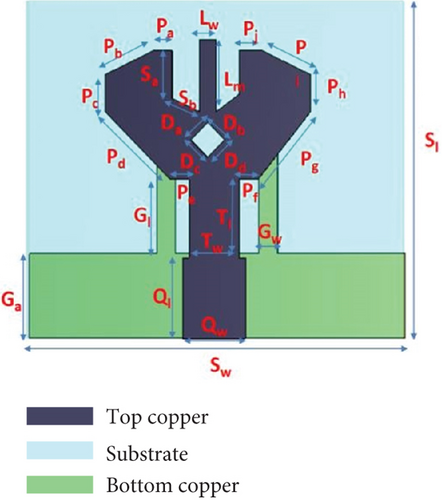
| Symbols | Measurements (mm) |
|---|---|
| Sl | 15.5 |
| Sw | 18 |
| Pa | 0.9 |
| Pb | 2.55 |
| Pc | 1.7 |
| Pd | 4.38 |
| Pe | 0.9 |
| Pf | 0.89 |
| Pg | 3.99 |
| Ph | 1.7 |
| Pi | 2.55 |
| Pj | 1.1 |
| L | 31 |
| Lw | 0.8 |
| Lm | 3.29 |
| Da = Db = Dc = Dd | 1.13 |
| Sa | 2.20 |
| Sb | 1.35 |
| Ga | 4 |
| Gl | 4.6 |
| Gw | 0.9 |
| T1 | 3.6 |
| Tw | 2.4 |
| Ql | 3.7 |
| Qw | 3 |
| W | 18 |
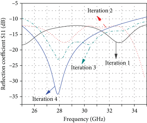
In Iteration 1 (Figure 2), the QWT and transmission line are connected with a simple rectangular patch that is located over the top surface of the substrate to boost the impact of capacitance that provides impedance matching with low losses. The full ground plane is designed over the bottom of the substrate. In this case, the target frequency range cannot be reached by the antenna, and the obtained bandwidth has a very low magnitude of −18 dB at 17.3 GHz (Figure 4). To improve the performance, the rectangular patch has been converted into an octagonal patch with the help of edge-cutting techniques, and the full ground plane is altered to less than partial ground, as represented in Iteration 2 (Figure 2). Although the bandwidth remains the same in this instance, with a lower magnitude of −16 dB up to 33.3 GHz and maximum magnitude of −27.9 dB observed at 35 GHz (Figure 4). Thus, antenna is unable to resonate within the intended frequency band. Further, the design is modified using diamond-shaped slot loaded in the middle of an octagonal patch, and two I-shaped stubs are included in the partial ground to lengthen the electrical path, as demonstrated in Iteration 3 (Figure 2). In this configuration, the antenna provides good reflection and wide bandwidth with an improved magnitude of −23.2 dB at the resonant frequency of 28.19 GHz (Figure 4). Further, the final antenna geometry is optimized to get the desired band by removing two quadrilateral-shaped notches from the top edges of the octagonal patch and increasing the length of I-shaped stubs in the partial ground to assist in parameter tuning and achieve the required frequency response, as shown in Iteration 4. In the final configuration (Iteration 4) (Figure 2), the antenna with wideband (S11 < −10 dB) is resonating at 28 GHz, and the maximum magnitude of −35 dB is attained by the single antenna. Thus, it is apparent from the graph (Figure 4) that with each iteration, the reflection coefficient achieved by the individual antenna improves. By optimizing the antenna design, the antenna has been organized to resonate at a 28 GHz band. The modified version of the rectangular patch for the desired band is the final design (Iteration 4), as shown in Figure 2. The result illustrates that the antenna functions well from 25 to 34.5 GHz while offering an impedance matching of 10 dB and a bandwidth of 9.5 GHz with a fractional bandwidth (FWP = 31.6%) for all iterations.
The octagonal shape provides a balance between achieving a wide bandwidth and maintaining good impedance matching. The geometry of the octagon allows for easier tuning of the antenna parameters to match the desired operating frequency, and it can potentially offer a broader bandwidth. The optimized design permits significantly improved performance characteristics.
Here, the speed of light c = (3 × 10⁸ m/s) and the estimated length of Gl is 4.6 mm at a notched frequency, as illustrated in Figure 5.
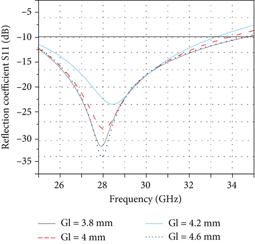
Figure 6a depicts the surface current distribution of a single antenna, demonstrating that the maximum current is concentrated near the feed line and the edges of the radiating structure and I-shaped stubs on the ground plane. It can be inferred that the inclusion of I-shaped stubs is crucial for achieving a desired resonant band at 28 GHz.
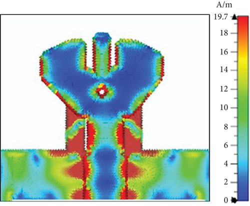
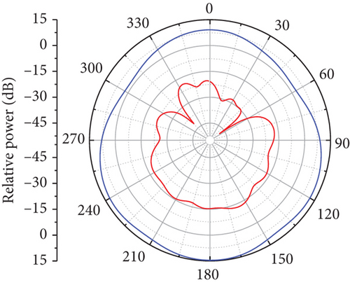
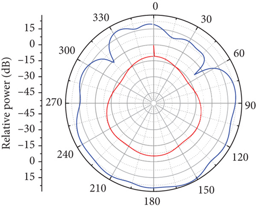
Figure 6b,c presents the two-dimensional (2D) radiation pattern of a single antenna operating at 28 GHz, illustrating its performance in both the E-plane and H-plane. The patterns display the copolarized and cross-polarized characteristics of the antenna.
The copolarized radiation pattern represents the energy radiated in the same polarization as the transmitted signal, while the cross-polarized pattern depicts the energy radiated in the orthogonal polarization. These patterns indicate that the antenna is highly directional, focusing its energy in specific directions and minimizing radiation in other directions. Furthermore, the distinct copolarized and cross-polarized radiation patterns help reduce interference from unwanted signals, improving communication reliability. The ability to control the radiation in both planes ensures that the antenna can efficiently transmit and receive signals, making it ideal for high-frequency applications such as satellite communication, point-to-point communication links, and radar systems.
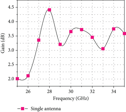
The simulated gain of a single antenna across its operating band is illustrated in Figure 7. The simulated gain exhibits a fluctuating trend, ranging from 2.13 to 4.41 dBi. Interestingly, the highest gain, 4.41 dBi, occurs at 28 GHz.
3. MIMO Configuration
Only one port is used in a single antenna, and several techniques are deployed to boost antenna gain, but most channel capacity issues are still critical. It requires the use of multiple ports to be effectively resolved by using MIMO architecture. A single antenna is slightly easier in the case of the MIMO technique. It might be difficult to manage the connection between identical radiators in a MIMO configuration. The single antenna has been converted into two two-element MIMO antennas in this segment. The proposed MIMO design maintains symmetry and preserves the original structure, with MIMO elements arranged in a face-to-face orientation, as demonstrated in Figure 8a. The fabricated model of the MIMO antenna (top and bottom view) is presented in Figure 8b,c, respectively. The dimensions of the total substrate utilized in the MIMO configuration, which measures 31 × 18 mm2, hold significant implications for the overall design and performance of the system. The face-to-face orientation of MIMO elements is also significant, as it facilitates the efficient coupling of the radiated signals from one antenna element to another. The dimensions of the substrate used in the MIMO configuration are also crucial, as they affect the performance of the antenna, particularly its resonant frequency and bandwidth.
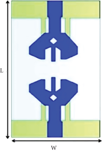
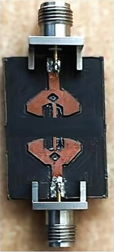
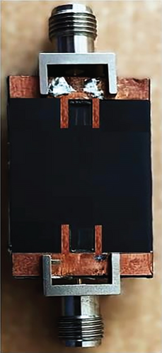
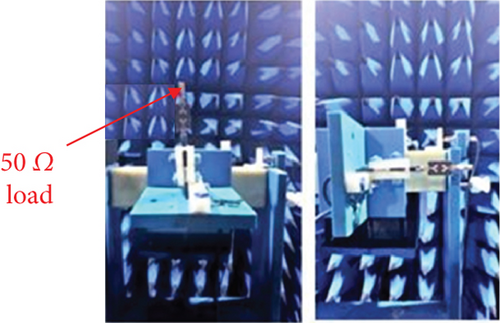
The antenna was analyzed using both simulation and experimental methods. Simulation work was performed with the CST software, while the experimental work involved fabricating the antenna using the LPKF laser and electronics E34, measuring the prototype with a Rohde and Schwarz vector network analyzer (VNA), and testing it inside an anechoic chamber. The antenna radiators were excited using a 50 Ω coaxial cable with an SMA connector. The MIMO antenna was evaluated based on various performance parameters, and the results were compared and discussed in this segment.
3.1. S-Parameters
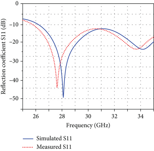
The simulated S-parameters are presented in terms of reflection (S11 and S22) and transmission coefficients (S12 and S21), as depicted in Figure 8 for both radiators about one another. For the two-element antenna, S11 and S22 show similar patterns, whereas S12 and S21 also show identical behaviour (Figure 9). The symmetry exhibited by the reflection and transmission coefficients for both ports of a two-element antenna is a desirable property that ensures predictable and controllable behaviour of the antenna system, making it more efficient and effective in 28 GHz band applications. Figure 10 illustrates the simulated and measured S11 coefficient for the MIMO configuration. The antenna has a 28.04 GHz resonance frequency with a minimum magnitude of −47.7 dB, providing a bandwidth of 26.25–35 GHz obtained from the simulated plot. In contrast to the measured (experimental) plot, the magnitude reaches up to −45 dB at 27.9 GHz, and the obtained bandwidth ranges from 25.29 to 35 GHz below 10 dB, as shown (Figure 10).
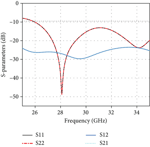
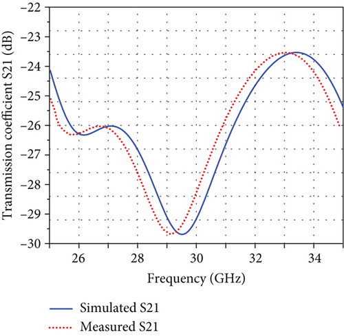
The isolation or mutual coupling consideration becomes especially crucial in a MIMO configuration when numerous antenna radiators are positioned close to each other. Efficiency, gain, and other aspects might be affected as a result of the mutually interfering effects. For the MIMO antenna, the isolation S21 is presented in Figure 11 along with an experimental analysis of it. The simulated and measured isolation achieved more than 23 dB, which is self-isolated, providing a low mutual connection between antenna ports. Additionally, there is a significant consistency and cohesiveness finding between simulation and experimental outcomes.
3.2. Surface Current Distribution
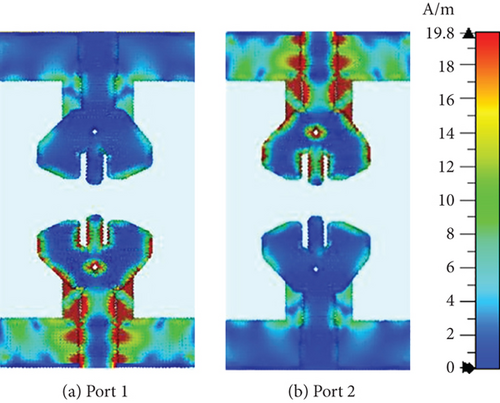
The analysis of the surface current distribution of the proposed MIMO antenna provides valuable insights into the impact of mutual connections between antenna elements. This analysis specifically focuses on the effects observed on the neighboring elements when one antenna element is excited. The surface current distributions of both radiators at 28 GHz are illustrated in Figure 12, which demonstrates similar responses for both ports. These patterns were obtained by exciting one port at a time while the other port was connected to a 50 Ω load. It is noteworthy that the largest current is dispersed across the feed line, the radiating structure, and the two I-shaped stubs added into the partial ground, while the lowest current is concentrated at the unexcited port. This suggests that the partial ground with I-shaped stubs plays a crucial role in achieving resonant and wideband performance.
3.3. Radiation Patterns
Figure 13a,b illustrates the simulated and measured 2D radiation patterns at 28 GHz for Port 1, showcasing the copolarized and cross-polarized components in the E-plane and H-plane. The patterns demonstrate that both radiators exhibit highly directional and focused radiation characteristics. The results show a remarkable alignment between simulation and measurement, with only minor discrepancies. These discrepancies are attributed to construction inaccuracies and connection losses. The radiation mechanism of the antenna is a crucial aspect to consider. At 28 GHz, the antenna design ensures that the radiated energy is concentrated in specific directions, enhancing the gain and directivity. The copolarized patterns indicate the primary polarization of the radiated wave, while the cross-polarized patterns provide insight into the polarization purity and the level of unwanted orthogonal polarization.
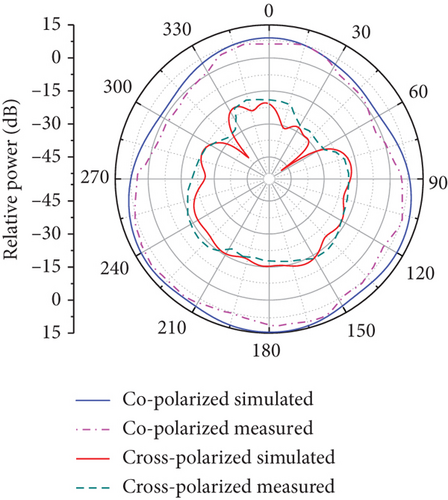
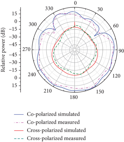
In the E-plane, which typically represents the elevation plane, the radiation patterns indicate how the antenna radiates energy vertically, while the H-plane, or azimuthal plane, shows the horizontal radiation distribution. The high directionality observed in both planes results from the antenna’s design, which includes elements such as parasitic directors, reflectors, or specific feed mechanisms tailored to focus the radiation.
These patterns are essential for applications requiring precise beam steering and high gain, such as point-to-point communication links and radar systems. The excellent agreement between the simulated and measured results validates the design approach and simulation models used, ensuring that the antenna performs as expected in real-world scenarios.
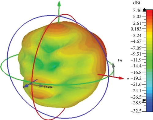
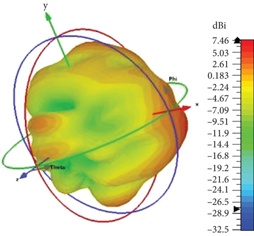
The radiation intensity of the antenna is aimed towards the broadside direction over the frequency band of interest, but it is slightly angled towards the upper direction due to the presence of a partial ground surface. This ground serves as a reflector, causing the beam to shift of the antenna. A measurement setup of radiation patterns inside an anechoic chamber is presented in Figure 14. The radiation patterns with respect to the directivity of a MIMO antenna are depicted in a three-dimensional (3D) format in Figure 15a,b. These patterns were generated at a frequency of 28 GHz for both ports of the antenna. The patterns provide a visual representation of the directivity radiation characteristics of the antenna. The 3D patterns of both ports show high directivity and have a narrow beamwidth; both radiators concentrate the radiated energy in a broad direction.
3.4. Gain
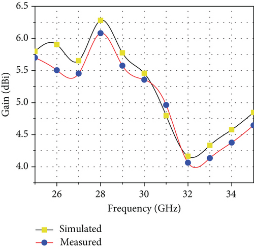
The overall gain of the MIMO antenna is presented in Figure 16. Contrary to a measured gain of the MIMO antenna, which varies between 4.23 and 6.46 dBi, the simulated gain varies from 4.18 to 6.46 dBi (see Figure 16). The gain increased by 2 dB when the single antenna was transformed into a two-element MIMO antenna. Thus, the simulated high gain value is 6.46 dB and measured at 6.18 dBi obtained at the main resonance frequency at 28 GHz.
3.5. Radiation Efficiency
Radiation efficiency quantifies how much of the input power is radiated as electromagnetic waves, rather than being dissipated as heat or lost in other ways. A higher radiation efficiency indicates a more effective antenna, capable of converting a larger proportion of the input power into useful radiation. Figure 17 represents the simulated and measured radiation efficiency of the proposed antennas. The simulated radiation efficiency is more than 95% at the resonance frequency of 28 GHz, and the measured efficiency is above 93%, which is hugely valuable for mm-wave systems.
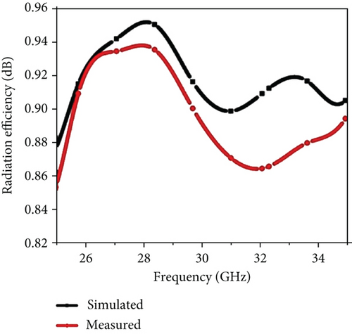
The measurements indicate a gain and radiation efficiency profile that closely matches the one estimated in simulations, albeit with a slight deviation towards higher frequencies.
3.6. Envelope Correlation Coefficient (ECC)
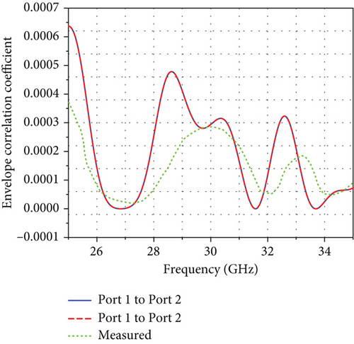
Another factor that indicates the level of connection between the various antennas that are close to one another is ECC. It can also be calculated using (8) and radiation patterns. According to Figure 18, the simulated ECC value for the MIMO configuration of the two-port antenna is below 0.00064, and the measured ECC is less than 0.0004 over the entire operating spectrum, satisfying the specific threshold condition of less than 0.5, indicating that separation among the antenna radiators is minimal.
3.7. Diversity Gain (DG)
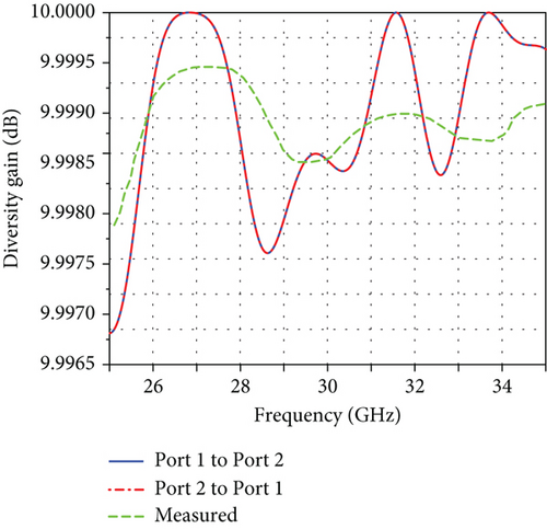
Although minor discrepancies have been observed between simulated and measured parameters, these differences are likely due to factors such as cable connections or measurement errors. However, all parameters remain within acceptable ranges and are considered reliable.
3.8. Total Active Reflection Coefficient (TARC)
Here, the symbol φ represents the phase difference between the excitation variances of the MIMO antenna. The TARC value corresponding to the proposed MIMO antenna configuration is illustrated in Figure 20. The illustration reveals that the TARC values maintain the inherent behaviour of the proposed MIMO antenna.
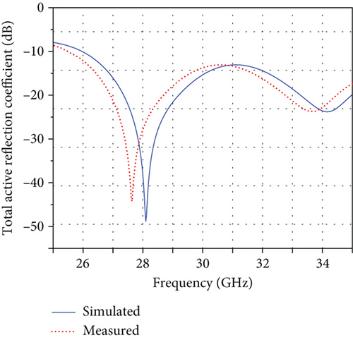
Table 2 provides a comparison of various MIMO antenna systems, including the proposed design. The table highlights the superior performance of the proposed design concerning several key parameters such as bandwidth, isolation, and diversity. Based on the outstanding results obtained from the proposed design, it is suggested that it has the potential to be integrated into modern wireless communication systems such as 5G and beyond, which operate at high frequencies in the mm-wave range. Overall, these results indicate that the proposed design shows considerable advantages concerning some existing MIMO antenna systems and may be an intriguing alternative to next-generation wireless communication systems.
| Ref. | Size (mm) | Size (λ) | No. of ports | BW (GHz) | Resonant frequency (GHz) | Isolation (dB) | Radiation efficiency | ECC | DG (dB) | Gain |
|---|---|---|---|---|---|---|---|---|---|---|
| [21] | 30 × 15 | 2.8 × 1.4 | 2 | 6.4 | 28 | 35.8 | 90% | < 0.005 | > 9.99 | 5.42 dB |
| [22] | 20.48 × 20.48 | 2.9 × 4.5 | 4 | 7 | 28 | > 20 | 94% | 0.006 | 9.97 | 6.87 dBi |
| [23] | 30 × 35 | 2.85 × 3.33 | 2 | 4.1 | 28.5 | 17 | 94% | < 0.01 | > 9.96 | 8.3 dB |
| [24] | 48 × 21 | 4.68 × 2.05 | 2 | 1.75 | 29.25 | 25 | 91% | < 0.4 | — | > 7 dB |
| [25] | 20 × 20 | 1.86 × 1.86 | 2 | 0.85 | 27.89 | 24 | 87% | < 0.4 | — | 8 dB |
| [26] | 31 × 48 | 2.9 × 4.5 | 4 | 5 | 28 | 21 | 93% | < 0.005 | >9.99 | 10 dBi |
| [27] | 31 × 31 | 2.9 × 2.9 | 8 | 3.68 | 28 | 16.1 | 94% | < 0.3 | — | 6.4 dBi |
| [28] | 22 × 13 | 2.83 × 1.67 | 2 | 17.5 and 2.4 | 24.6–42.1 and 50.1–52.5 | > 40 | > 97% | 0.0038 | > 9.999 | 6.72 dB |
| [29] | 43.611 × 43.611 | 5.6 × 5.6 | 4 | 1.15 and 0.6 | 28/37 | 20 | 98% and 91.4% | 0.0065 | > 9.997 | 7.9 and 13.7 dB |
| Proposed work | 31 × 18 | 2.9 × 1.68 | 2 | 8.7 | 28 | 24 | 95% | < 0.0007 | > 9.99 | 6.46 dBi |
4. Conclusion
The work was aimed at developing a 28 GHz MIMO antenna for satellite communication, starting with the design of a single octagonal-shaped antenna that operates at 28 GHz with superior wideband performance. This antenna features a partial ground plane and I-shaped stubs, which create resonant bands at 28 GHz, achieving an impressive gain of 4.52 dB and an impedance bandwidth of 10 dB. Built on this ground, the single antenna was escalated to a two-element MIMO system with considerable improvement in the overall performance. This MIMO configuration demonstrates good broadband coverage and a sharply increased high gain of 6.46 dBi. The MIMO setup revealed a stunning 10 dB impedance bandwidth from 25.3 to 35 GHz and more than 23 dB isolation in the entire band of operation. Specifically, the very directive patterns of radiation and great performance in terms of diversity make the MIMO antenna a highly suitable candidate for the 28 GHz band and satellite communication applications. The measured results of the MIMO antenna further show that they are in complete agreement with the simulated results, proving it to be a distinctive design, possessing great functionality and remarkable characteristics.
Ethics Statement
The authors have read, understood, and agreed to comply with the ethical and legal guidelines outlined in this declaration.
Conflicts of Interest
The authors declare no conflicts of interest.
Funding
There is no funding support that has been provided for the presented work.
Open Research
Data Availability Statement
All data that support the findings of this study are included within the article.


