Design and Simulation of a Four-Legged Mobile Robot for Autonomous Navigation on a Spacecraft Hull
Abstract
This study presents the design and simulation of a four-legged mobile robot engineered for autonomous navigation on the exterior surface of a spacecraft hull. Unlike existing space robotic systems that rely on fixed infrastructure or operate in structured environments, this quadruped robot is designed to traverse complex, nonplanar hull geometries without external support. The robot integrates global path planning using Dijkstra’s algorithm with real-time orientation correction via an onboard MPU-6050 IMU, enabling it to align with waypoints and minimize positional drift during movement. To evaluate performance, a 2D representation of a spacecraft hull was used, and three test runs were conducted. The robot demonstrated the ability to follow the computed optimal path with a positional deviation of less than 0.5% by the third trial. Positional error was quantified per waypoint and summarized using average and standard deviation metrics, while total traversal distances ranged from 65.50 to 63.00 in., approaching the theoretical minimum of 62.70 in. These results highlight the robot’s iterative improvement in trajectory tracking and its potential for future use in autonomous on-orbit servicing and spacecraft inspection applications.
1. Introduction
In recent decades, the exploration and utilization of space has advanced significantly. Spacecraft and satellites now play pivotal roles in scientific discovery, defense operations, and global communications. These missions aim to uncover crucial insights into the solar system and beyond [1]. However, spacecraft development entails complex engineering processes to withstand extreme space conditions, including high radiation levels, wide temperature fluctuations, and persistent exposure to micrometeoroids and orbital debris [2]. Even with rigorous design protocols and extensive ground testing, unforeseen challenges such as mechanical failures, material degradation, and system malfunctions continue to threaten mission success once in orbit [3].
To address these challenges, robotic technology has emerged as a vital tool for spacecraft maintenance, inspection, and repair [4]. Recent advancements in space robotics emphasize the growing importance of autonomous systems in reducing astronaut risk and extending mission capabilities. Traditional robotic assets, such as the Canadarm2 [5, 6], Robonaut [7, 8], and Eurobot [9], laid the groundwork for orbital manipulation and EVA assistance. More recently, modular and autonomous systems are being explored to support increasingly complex on-orbit servicing, assembly, and manufacturing (OSAM) tasks. Yang et al. [10] presented a reconfigurable robot for in-orbit assembly, while Zarei and Chhabra [11] analyzed evolving trends in planetary wheeled mobility. Dunker et al. [12] developed a SLAM-enabled, bio-inspired robot for adaptive surface traversal in lunar-like terrains. Yoshida and Wilcox [13] emphasized the value of manipulator-equipped free-flyers for untethered servicing tasks. Free-flyers such as NASA’s Astrobee leverage vision-based navigation and modularity to perform inspection and logistics aboard the ISS [14, 15] while Cauligi et al. [16] extended Astrobee’s capabilities using gecko-inspired adhesion for microgravity perching. Hou et al. [17] proposed integrated robotic servicing concepts combining navigation, control, and modular manipulation.
Parallel developments in terrestrial robotics provide promising strategies relevant to space environments. Wu et al. [18] introduced an adaptive fault-tolerant control strategy for quadruped robots, enhancing resilience under actuator degradation scenarios. Li et al. [14] emphasized the integration of mechanical design with real-time learning algorithms for adaptive gait control across rough terrain, while Jin et al. implemented a visual SLAM-based framework enabling quadrupeds to navigate cluttered and confined environments [15]. Liang and Wu [19] addressed computational constraints through a lightweight object detection framework for edge devices, and Moshayedi et al. [20] demonstrated how adaptive motion planning with visual feedback improves field robot performance in unstructured environments. Zarei et al. [21] presented a vision-based real-time detection solution for limited-resource systems, highlighting methods applicable to embedded space platforms. Ground-based indoor service robots like FoodieBot use efficient path planning and obstacle avoidance for autonomous operation [22], offering insights despite their flat and feature-rich environments.
Collectively, these studies reflect progress toward autonomous robotic mobility; however, no existing work addresses the specific challenge of autonomous traversal and servicing directly on curved or irregular external surfaces of spacecraft. While servicing missions like NASA’s Robotic Refueling Mission (RRM) [23, 24] and Northrop Grumman’s Mission Extension Vehicle (MEV) [25, 26] have demonstrated the feasibility of on-orbit servicing, they remain largely ground-supervised and lack autonomous navigation. A robot capable of traversing external spacecraft surfaces must integrate advanced navigation, orientation control, and environmental resilience within a lightweight, power-efficient form factor. Addressing this challenge demands novel approaches to locomotion and path planning that are inherently suited to microgravity and irregular geometries, highlighting a critical gap in current OSAM robotic capabilities.
The proposed study introduces a quadruped robotic platform designed to traverse the exterior of a spacecraft using a Dijkstra-based path planning algorithm. The robot features an onboard MPU-6050 inertial measurement unit (IMU) for real-time orientation feedback and yaw correction, enabling accurate trajectory tracking without reliance on GPS or visual markers. The objectives of this work are threefold: (1) to design and simulate a legged robot for navigating external spacecraft geometries; (2) to integrate a hybrid navigation system combining global Dijkstra path planning with local IMU-based correction; and (3) to evaluate positional accuracy and trajectory stability in simulated environments. This work contributes a scalable, power-efficient solution for autonomous spacecraft servicing, reducing astronaut risk and enabling future orbital missions that require agility, adaptability, and resilience.
2. Materials and Methods
2.1. Spacecraft Model Hull
Current literature indicates space’s harsh conditions include but are not limited to temperature spikes, micro-gravity, radiational surges, cabin pressure spikes, debris impact, and vibrations [27]. The temperature inside a space shuttle stays around 77 °F while space’s temperature ranges anywhere from –150 to 550 °F according to NASA’s state of the art of small spacecraft technology. Radiation levels in space are observed to be higher than in Earth’s atmosphere indicative that the material used must be able to resist and withstand higher amounts of radiation. To better decide on a material for the space hull/space shuttle’s surface, current space environmental conditions were considered. The cabin pressure is estimated from inside to exert about 15 psi. The material used for the surface should be able to withstand that type of pressure. If not, the outcome can be extremely dangerous and fatal to the space shuttle and all on board. When launching a spacecraft into space, the spacecraft can experience up to three times the gravitational force that is experienced on Earth. The spacecraft material should be able to withstand deployment into space and re-entering the Earth’s atmosphere with gravitational, temperature, and velocity conditions.
Given space’s conditions and limitations, the material properties determined for the spacecraft’s surface are specific strength as well as specific rigidity [28]. For control stability reasons, magnetic metallics are avoided in the decision process. Current space shuttles and rockets use aluminum alloys and graphite-epoxy composites. Certain applications utilize aluminum alloys, however; higher thermal conductivity is required for its use. Magnesium is another material consideration for space application, but extra care is needed to prevent corrosion. The most typical alloys that are used are A7075 and A2024.
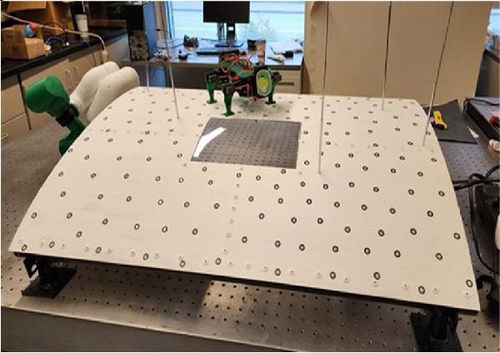
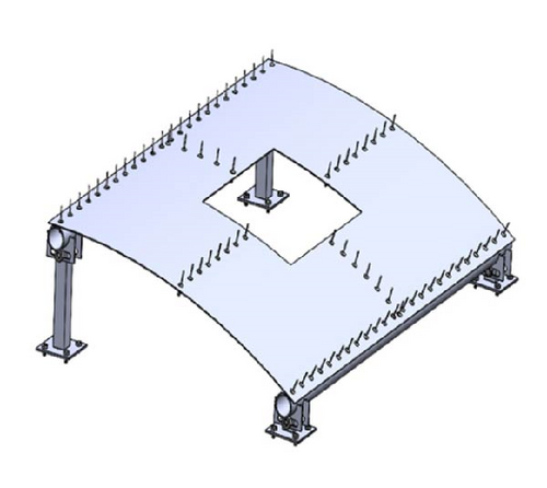
To reproduce a spacecraft’s surface, a sheet of aluminum 3003 was cut to 3 ft wide by 2 ft long with a thickness of 0.063 in. This aluminum material was decided for ease of machinability. The final hull design has a radius of curvature of 45 in., so it is curved but still manageable for the robot to maneuver on as shown in Figure 1. Different spacecraft features are attached to the surface of the spacecraft’s hull. Such features serve vital functions to the shuttle. Some examples are antennas, thermal control boxes, power grids, windows, and communication technology. Due to size restrictions and robot maneuverability, antennas, and windows became the main priority components to be featured on the hull. The center of the hull was cut out, and plexiglass was molded to the curve and bolted to the hull to simulate a window.
2.2. Robot Design
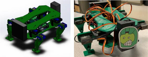
The quadruped robot introduced in this paper contains different elements. Inspired by the works from FLIMAR and LEMUR, one of the primary goals was to achieve stability with four legs [29, 30]. More importantly, the motivation behind choosing four legs was minimizing the number of servos controlling the legs, optimizing the system for energy efficiency. The design consists of a 3D printed top body, bottom body, and four legs. Each leg is controlled via two servo motors connected to a microcontroller (Arduino Uno) to help manage the gait movement of the robot. Legs aren’t similar locomotion elements like wheels therefore added joints allow for lifting of the robot’s legs. Each leg contains 2 degrees of freedom (DOF), one at the hip and one at the knee. Each hip and knee of the robot was equipped with a MG90 servo motor. The torque rating for MG90s servo motors running at 6V battery is 2.2 kg cm. These 2DOF allow for the robot to maneuver forward and backward while lifting and dropping its feet. Each freely swinging foot has a piston-analogous structure for movement as shown in Figure 2. Thus, the feet are not wobbly, and the feet’s movement can extend/distend. Preliminary results indicated the robot could move forward and backward on a flat surface at a speed of 0.355 in/s recorded by the microcontroller.
2.3. Denavit Hartenberg (DH) Parameters
The Denavit Hartenberg (DH) parameters are a standardized method in robotics for modeling the kinematic chains of manipulators. By identifying a set of four parameters, that is, link length, link twist, link offset, and joint angle, the DH convention simplifies calculation and representation of each joint transformation matrix within a robotic system. In the context of a 2DOF servo motor configuration, the DH parameters are applied to map relative positions and orientations necessary for the two joints to work as a robotic leg to achieve desired locomotion. These parameters facilitate the construction of kinematic equations, which describe the movement and reach of a given system, ensuring precise control and predictable end-effector behavior through operation.
2.4. Forward Kinematics
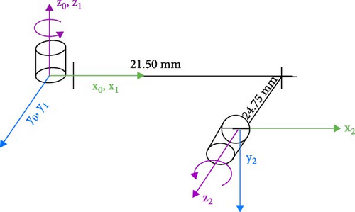
Forward kinematics involves the use of the DH parameters as a modeler of the kinematic chain of the robot and computes the position and orientation of the end effector. By defining the DH table, each link and joint in the system is characterized, simplifying transformation matrices necessary for the leg’s overall motion as shown in Figure 3 and Table 1.
| Joint (n) | θn | dn | ln | αn |
|---|---|---|---|---|
| 1 (hip) | θ1 | 0 mm | 0 mm | 0 |
| 2 (knee-foot) | θ2 | 24.75 mm | 21.50 mm | 90° |
Transformation matrices reflect the rotations and translations done across different axes. Four transformations are done to go from one joint to the next. To best represent the full transformation matrix, we multiply the following together to achieve a full transformation matrix from one joint to the next.
Orientation is solved by taking the general representation of rotation matrices, multiplying them together, then manipulating them to achieve the desired roll–pitch–yaw orientations.
2.5. Inverse Kinematics
2.6. The Robot’s Forward Gait
Once the quadruped design for the mobile robot was finalized, a suitable gait needed to be designed and coded. FLIMAR’s extra servo motor in each leg enables better stability and recovery on 4 ft. [29]. Therefore, the goal of this gait, shown in Figure 4, was for the robot to walk as naturally as possible on the lab-based model space hull. After studying the movement of reptiles, a potential gait was decided upon. Initially, the robot lifts two opposite legs—either the front-right and back-left, or the front-left and back-right. At certain points in the gait cycle, both legs on opposite sides of the robot are lifted off the ground simultaneously. However, stability is maintained by ensuring that the remaining two legs on the opposite sides are always in contact with the ground. This creates a dynamic yet stable base of support, allowing the center of gravity to remain within the bounds of the grounded legs. As the lifted legs return to the ground, the opposing set of legs lifts, repeating the process. This phased coordination ensures that despite brief periods of reduced ground contact, the gait remains stable and efficient for forward motion, even on uneven surfaces.

2.7. Robot Rotation
For precise rotation while maintaining stability of the quadruped robot, the rotational movement is carefully synchronized with the forward gait. For a clockwise turn, the robot lifts the front-right and rear-left legs, similar to the forward movement pattern where opposing legs lift. The front-right left moves forward and outward at a controlled angle, while the rear-left leg moves backward and outward, creating a rotational force. The other two legs, the front-leg and rear-right, which remain in contact with the surface, help to stabilize the robot and refine the turning radium. These legs adjust their position slightly by taking shorter, inward steps, ensuring that the robot maintains a stable two-point contact with the surface as it rotates. The center of gravity shifts slight to the left to further aid the clockwise rotation.
In the case of counterclockwise turn, the robot follows a mirrored pattern. The front-left leg and rear-right legs are lifted, and the front-left leg moves forward and outward at a controlled angle, while the rear-right leg moves backward and outward. The remaining legs, front-right and rear-left, take shorter, inward steps, to help refine the rotation and maintain stability. The center of gravity shifts slightly to the right to ensure balance during the turn. By precisely controlling the movement of the legs while keeping at least two points of contact with the surface, the robot can achieve smooth controlled turns while maintaining stability.
2.8. Robotic Dijkstra Path-Planning
The quadruped robot designed in this paper aims to autonomously navigate a model spacecraft hull, utilizing an optimal path-planning approach. Compact and energy efficient, the robot can adapt to dynamic, unpredictable environments. The primary objective is to compute an effective path to a specific destination on the spacecraft hull while avoiding obstacles. For this purpose, the robot uses the Dijkstra algorithm (DA), which computes the optimal path in a workspace mapped using visibility graphs and Voronoi diagrams [31, 32]. Previous research, including NASA work, has explored the application of the DA for similar autonomous navigation tasks, provided a technical foundation for the design [33, 34].
In this feed-forward control system, an MPU-6050 IMU was utilized to for positional sensing and angular orientation, enabling the quadruped to execute precise rotation and controlled forward movements. The MPU-6050 is a 6DOF sensor integrating a three-axis gyroscope and three-axis accelerometer. This IMU was chosen of its ability to provide accurate angular orientation through its onboard digital motion processor (DMP), which computes orientation data in real-time. The MPU-6050 supports a sampling rate of up to 1 kHz and features an I2C interface for easy integration with the microcontroller, making it well-suited for precise motion control in the robot. Leveraging the IMU data allows the microcontroller to assess if the robot’s orientation in real-time, adjusting each leg’s movement to align with the desired rotational angle and forward trajectory. The use of IMU for orientation and positional feedback allowed for efficient control, where the robot-maintained stability and accurate directional movement without relying on complex external sensors or reactive feedback loops. The IMU data provided a clear picture of the robot’s position ensuring smooth and calculated turns with forward movement and little deviation.
The intended goal for the mobile robot is to compute a path planning algorithm that will allow the mobile robot to navigate on the hull to find damaged sections in an energy efficient and obstacle avoidance manner. The DA allows for the cellular mapping of the workspace. This can then contain different obstacles placed on the map. Therefore, the rivets, antennas, and windows are marked as obstacles. Prior to constructing paths on the DA, an integrated position sensor (IMU) and digitized “map” of the hull are required for path planning. The robot’s position is indicated on the spacecraft hull given in position and orientation (six coordinates). The map is a representation of the workspace that the mobile robot will traverse including the different obstacles it may encounter. Figure 5 illustrates the obstacles in a dark blue color. After producing a map representation of the space hull, referencing the mobile robot’s location, and verifying the mobile robot’s dimensions, each of these obstacles are grown. The corners of the grown obstacles are then denoted as nodes along with any visible corners clear from them as possible segments the robot can take. Full lists of the nodes and segments are inputs to the DA in which the output will give the shortest path between two points on the hull. The green path shown is the shortest path. Any small obstacles on the hull are shown in different colors. Rivets are illustrated in red, and screws are magenta. As the robot can still pass over them, they are included for visualization.
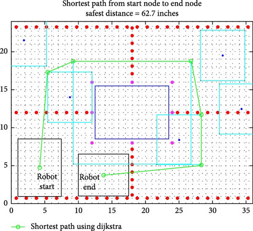
Prior to beginning the path-planning implementation, the IMU yaw angle is referenced and zeroed at the normal/90-degree orientation of the model spacecraft hull. This step establishes a baseline for the robot’s angular orientation with respect to the hull, ensuring that all subsequent rotational movements are calculated in this reference frame. To test the path planning capability of the DA, a random start and end point were generated as a source of the robot’s home and destination site. The shortest and safest distance is 62.7 in. (1.59258 m) to get around the oversized obstacles without any interference or collision. The robot’s control system then will perform rotations while moving forward. The safest path demonstrated in Figure 6 is based on linear lines consisting of two 2D coordinates. Mathematically, taking the inverse tangent of the difference between the y-values and x-values calculates the angle to the normal required for rotation of the mobile robot. The equations are as follows:
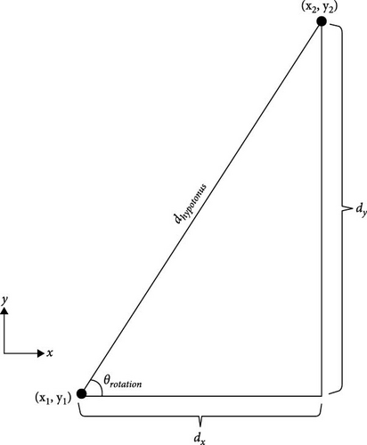
To coordinate the robot’s rotation to this, the IMU’s yaw angle is to be aligned with the angle of rotation given by the DA. In this case, it becomes an optimization control problem to minimize the error in terms of comparison to a desired rotation angle compared to the robot’s IMU yaw angle as shown in Figure 7.

The diagram illustrates the input of the desired rotational angle, which is derived from the Dijkstra map calculations described earlier. The current yaw angle from the MPU-6050 is fed into the system, and the difference between the desired and current yaw angles generates an error signal. This error is then processed by a PID controller, which fine-tunes the robot’s rotation to minimize the error, aiming the achieve the exact Dijkstra rotational angle (θ). The PID gains are configured via PID tuner in MATLAB. At each waypoint of the DA, the controller operates in a loop, allowing the robot to perform precise rotations with minimal error.
The velocity and position of the mobile robot are derived using raw acceleration data obtained from the IMU sensor. To ensure accurate position estimation, the raw IMU acceleration values are first processed and converted into velocity and displacement. This includes a sensitization step, where noise filtering and calibration are applied to account for sensor drift and external disturbances. Using the processed data, the robot’s position is estimated in the x and y coordinate frame relative to the mobile robot’s starting point or global reference. These estimated positions are compared against predetermined waypoints generated by the Dijkstra map to evaluate the robot’s adherence to the planned trajectory.
Velocity is computed with inputs of the current linear acceleration provided by the IMU and the initial velocity which is assumed 0 at the start of the path-planning procedure. The following equations represent the integrations done in the x and y directions as the robot traverses in that direction.
After calculating the Euclidean distance, a safety margin of 0.013 m is applied to ensure the robot successfully stops at the waypoint before initiating any rotational movement. Once the robot moves forward and performs rotations at specific waypoints to reach desired angles, it arrives at the final destination and transitions into standby mode, completing the path-planning process. The mobile robot efficiently navigates and avoids obstacles through the DA, executing the planned path as intended.
3. Results and Analysis
The layout of the model spacecraft hull is designed to emulate the curved and irregular surfaces encountered in space’s environment. This layout serves as the ideal testbed for simulating the mobile robot’s ability to navigate a complex, nonplanar surface. The hull’s rounded rectangular shape presents challenges for movement, adherence, and precise path-following—all of which are critical for on-orbit servicing tasks in space. The primary objective of this study is to simulate the mobile robot’s ability to accurately and autonomously follow the computed Dijkstra’s fast path, especially in non-linear layouts, where precision in rotation and localization is essential for maintaining an intended route.
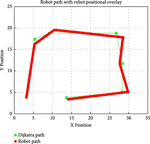
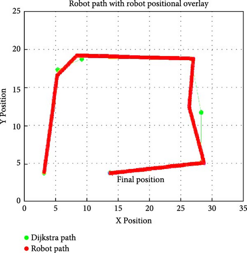
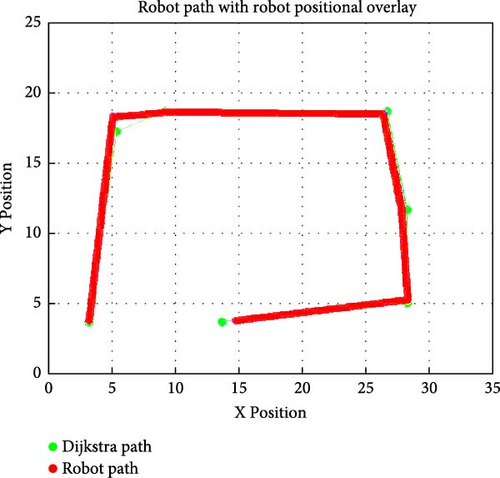
The mobile robot’s path following capability is examined based on a 2D representation of the hull using the DA. By simplifying the complex 3D surface into a 2D layout for the Dijkstra map, elements can be isolated and refined for path accuracy, waypoint alignment, and the robot’s responsiveness to control inputs. This 2D representation allows for initial validation of the robot’s ability to follow a computed fast path, laying a foundation for adapting the navigation techniques to more complex 3D surfaces in subsequent phases. MATLAB recorded the robot’s position in x and y to overlay it on top of the current path selected in the Dijkstra map shown in Figure 8. Physical comparative values of the three test runs against the Dijkstra’s waypoints are in supplemental data (see Supporting Information Table S1). Three runs were performed to compare the position of the mobile robot to the waypoints that are set by the Dijkstra map. Table 2 displays the positional x and y error observed between the Dijkstra path waypoints and the mobile robot’s achieved positions.
| Waypoint index | Run #1 error % (x) | Run #1 error % (y) | Run #2 error (x) | Run #2 error % (y) | Run #3 error % (x) | Run #3 error % (y) |
|---|---|---|---|---|---|---|
| 1 | 0.00 | 0.00 | 0.00 | 0.00 | 0.00 | 0.00 |
| 2 | 6.45 | 5.04 | 0.32 | 6.28 | 0.26 | 6.02 |
| 3 | 0.11 | 0.51 | 0.11 | 0.51 | 0.31 | 0.53 |
| 4 | 0.15 | 4.31 | 0.60 | 4.31 | 0.64 | 5.25 |
| 5 | 2.26 | 0.09 | 0.04 | 17.76 | 1.41 | 4.34 |
| 6 | 2.61 | 1.86 | 0.15 | 3.36 | 0.03 | 18.34 |
| 7 | 3.56 | 12.90 | 3.56 | 10.24 | 8.10 | 2.52 |
| Average ± std dev (%) | 2.16 ± 2.36 | 3.53 ± 4.60 | 0.68 ± 1.29 | 6.06 ± 6.22 | 1.54 ± 2.93 | 5.29 ± 6.19 |
The development and simulation of a four-legged mobile robot equipped with locomotive intelligence shows great promise for autonomous navigation on a simulated space model hull. The robot demonstrates its proof of concept by traversing a 2D modeled spacecraft hull, computing a modified DA to navigate around given obstacles while executing rotational and forward movement. By using an IMU, the mobile robot interprets the Dijkstra-generated waypoints through mathematical manipulation, enabling precise rotation at critical nodes and forward motion with safety margins to avoid collisions. Results from three test runs highlight the system’s iterative learning capability: Run #1 achieved a total traversal distance of 65.50 in. (1.664 m), a 5% deviation from the algorithm’s theoretical minimum (62.70 in./1.593 m) due to rotational overshoot at waypoints 2 and 7. By Run #3, the robot optimized its path to 63.00 in. (1.600 m), reducing deviations to <0.5% in critical segments (e.g., waypoints 3–5 with x-errors <1%) and demonstrating adaptive prioritization of safety margins over strict path adherence at Waypoint 6, where a transient 18.34% y-axis deviation occurred to avoid obstacles. This refinement reduced cumulative traversal distance by 3.8% across runs, aligning closely with the Dijkstra path in later trials. Upon reaching the goal, the robot entered standby mode, confirming successful map fulfillment with minimal positional drift. While these advances underscore the robot’s potential for autonomous space servicing, challenges persist in real-time rotational control and sensor-driven localization, particularly during complex maneuvers. Addressing these limitations will enhance reliability, further reducing the need for astronaut intervention in extraterrestrial missions.
4. Discussion
The proposed prototype demonstrates a robust integration of Dijkstra’s global path-planning with basic locomotion capabilities on a model spacecraft hull, achieving sub-0.5% positional deviation over trials. However, to progress toward a fully autonomous space-servicing robot, future work must focus on four critical areas: dynamic path replanning, advanced multi-modal localization, space-grade adhesion, and enhanced kinematic configurations. Addressing these dimensions will not only mitigate current limitations but also propel the field of space robotics and on-orbit servicing by providing a scalable platform capable of adaptive navigation.
To move beyond the current prototype and ensure full autonomy in navigation, future iterations of the robot will incorporate a multi-sensor fusion system that includes an embedded camera, IMU, and potentially LiDAR or ultrasonic sensors. This suite of sensors will enable real-time positioning and environmental awareness, addressing the current lack of localization feedback. While the embedded camera will be used for image processing and AprilTag detection providing robust relative localization via fiducial markers strategically placed on the spacecraft hull, complementary use of an IMU will ensure stable pose estimation during motion. AprilTags will be distributed to maximize field of view coverage with redundancy while avoiding optical conflicts by using variable sizes and marker groupings in known geometric patterns. For more precise obstacle detection and mapping in 3D, LiDAR, or depth cameras will be considered, enabling dynamic obstacle avoidance. Localization data from these sensors will be fused using Extended Kalman Filters or factor graph SLAM methods, facilitating real-time updates to path planning.
DA delivers an optimal shortest-path solution on a fully known, static graph, but it inherently assumes that edge costs and network topology remain unchanged, making it unsuitable for environments where obstacles move or terrain properties evolve in real time [35]. To overcome this limitation, our roadmap incorporates D ∗ Lite, an incremental search algorithm that efficiently repairs shortest-path trees in response to changes in edge costs whether due to newly discovered obstacles or dynamic terrain variations without re-expanding the entire graph [36, 37]. Building on D ∗ Lite, we will adopt improved anytime dynamic A ∗ (iADA ∗), which computes bounded-suboptimal paths rapidly and then refines them as fresh sensor data arrive, ensuring the robot can initiate motion before full convergence, a capability shown to improve responsiveness by up to 50% in dynamic robotics scenarios [38, 39]. Real-world locomotion further demands collision avoidance that respects the platform’s kino-dynamic constraints; to this end, we will fuse global replanning with an Enhanced Dynamic Window Approach, integrating obstacle-aware velocity sampling to react to hazards within milliseconds while observing the robot’s dynamic limits [40]. Hybrid planners that combine D ∗ Lite’s global map updates with DWA-based local control have demonstrated over a 40% reduction in collision rates and a 30% improvement in trajectory smoothness in unknown indoor environments, stressing the efficacy of this two-tiered strategy [41]. In scenarios where the robot incrementally builds its environmental model such as upon first contact with an uncharted spacecraft surface, we will leverage Lazy Incremental Search techniques (e.g., Lifelong-GLS and Bounded L-GLS) to treat continuous map updates as lightweight adjustments to the search tree, minimizing redundant computation and accelerating replanning times by up to 60% compared to full graph replanning [42]. Collectively, these dynamic and anytime planning methodologies will transform the static-graph Dijkstra prototype into a responsive navigation system capable of safe, autonomous operation in uncertain, evolving terrains geared toward on-orbit servicing missions.
Space-grade adhesive integration will be implemented at the robot’s foot interface using a hierarchical PDMS microstructure fabricated via soft lithography, generating micron-scale wedge arrays topped with sub-100-µm spatulae—a design shown to achieve shear strengths exceeding 80 kPa and reversible adhesion in vacuum conditions [43, 44]. Initial characterization of adhesive performance under thermal extremes (–120°C to + 120°C) and vacuum will leverage university-based thermal-vacuum chambers, following methodologies from recent multiscale synergistic PDMS adhesive studies that reported stable adhesion over 100 cycles with negligible strength loss [45]. To validate behavior in true microgravity, parabolic-flight experiments will collaborate with government programs (e.g., NASA Flight Opportunities) and industry partners, building on protocols where gecko-inspired adhesives maintained consistent gripping forces across dozens of weightless arcs. In-orbit performance data from Astrobee free-flyer trials aboard the ISS which achieved sustainable adhesive grip forces exceeding 3 N after prolonged storage will further inform design refinements for space-qualified grippers [46, 47]. Contamination and surface-fouling, identified as primary failure modes in recent gecko-adhesive reviews, will be mitigated through substrate plasma cleaning and UV–ozone treatments serving as techniques to restore over 90% of PDMS adhesion post-exposure [48]. Wear-resistance will be evaluated in cleanroom settings using standardized orbital dust simulants over 10,000 adhesion–release cycles, targeting greater than or equal to 80% retention of shear strength in line with literature benchmarks for mechanically robust PDMS microstructures [49]. Collaborative efforts with industrial partners will incorporate insights from recent variable-stiffness gecko-inspired adhesive developments for non-cooperative object capture in microgravity. Ultimately, this hybrid university–government–industry test campaign will bridge the gap between laboratory prototypes and flight-ready adhesive systems for on-orbit servicing applications.
While the quadruped prototype demonstrated baseline locomotion capabilities, it exhibits stability limitations when traversing uneven or inclined surfaces. Transitioning to a hexapod configuration enables statically stable alternating-tripod gaits, where at least three legs always remain in contact with the surface significantly improving balance, fault tolerance, and climbing efficiency. Recent studies have demonstrated terrain-adaptive gait strategies for legged robots that dynamically adjust swing clearance, step height, and duty factor in response to sensed terrain irregularities, improving traversal success by over 20% in cluttered and rough environments [50]. To further enhance adaptability and autonomy, future iterations of the platform will integrate reinforcement learning–based gait selection frameworks, such as proximal policy optimization (PPO), which have shown promise in evolving efficient locomotion strategies for hexapods operating in unstructured terrains [51]. These learning-driven controllers allow robots to adapt leg trajectories to unmodeled or shifting surface features while maintaining overall stability. Coupled with high-fidelity proprioceptive sensing and gecko-inspired adhesion, the proposed hexapod will offer a robust platform for on-orbit servicing tasks, where safe surface traversal, fault recovery, and payload manipulation are critical for success.
5. Conclusions
This study presents a four-legged autonomous robot capable of navigating simulated spacecraft hulls using a hybrid Dijkstra-IMU architecture, achieving <0.5% positional deviation in critical segments and reducing traversal distances by 3.8% across iterative test runs. By integrating global path planning with real-time IMU feedback, the robot demonstrated precise waypoint alignment and adaptive obstacle avoidance, traversing a 2D hull model with runs converging to 63.00 in. (1.600 m) from the Dijkstra-calculated 62.70 in. (1.593 m). These results validate the feasibility of legged robots for structured spacecraft surface navigation, offering a scalable foundation for autonomous on-orbit servicing. However, challenges in real-time sensing, dynamic obstacle handling, and adhesion in microgravity highlight the need for future innovations. Proposed solutions include sensor fusion (LIDAR, camera, IMU, and AprilTags) for robust localization, D ∗ Lite path planning for dynamic environments, and gecko-inspired adhesives tested in thermal-vacuum chambers for space-grade grip. Transitioning to a hexapod platform with reinforcement learning-driven gaits could further enhance stability on irregular surfaces. By addressing these limitations, this work paves the way for autonomous robots to perform high-risk inspections, repairs, and refueling missions in space, reducing astronaut dependency and advancing sustainable space exploration.
Conflicts of Interest
The authors declare no conflicts of interest.
Funding
No funding was received for this manuscript.
Acknowledgments
The authors have nothing to report.
Supporting Information
Additional supporting information can be found online in the Supporting Information section.
Open Research
Data Availability Statement
The data that support the findings of this study are available from the corresponding author upon reasonable request.


