An Analytical Inspection on Effect of Chemical Reaction and Radiation on MHD Biviscous Bingham Tetra Nanofluid Flow With Accelerated Plate
Abstract
The nanofluids and their advanced models (ternary and tetra nanofluids) possess an outstanding thermal mechanism and attract engineers and industrialists with their prominent features. Tetra nanofluids have high thermal conductivity; thus, by inserting nanoparticles in the base fluids, the effective thermal conductivity of heat transfer fluids is enhanced. A framework has now been illuminated throughout this work to scrutinize the behavior of chemical reactions and radiation on water-based magnetohydrodynamics (MHD) biviscous Bingham flow of tetra nanofluid (Al2O3–Fe3O4–TiO2–Cu/H2O) over an accelerated plate through a porous medium in the presence of slip conditions, heat source/sink, and viscous dissipation. The overall physical problem is designed in the form of a nonlinear partial differential equation, which is then altered into a highly nonlinear ordinary differential equation via a proper dimensionless variable. These equations are solved analytically, along with the associated boundary conditions. The flow, energy, and mass problems were examined analytically, especially the heat transport phenomena performed for both prescribed surface temperature (PST) and prescribed heat flux (PHF) cases, and mass transfer was also evaluated in two different cases, namely prescribed surface concentration (PSC) and prescribed mass flux (PMF) cases, and then, these solutions were demonstrated in terms of the confluent hypergeometric function. There were plots showing how the different variables affected the velocity of flow, energy, concentration, skin friction, and rate of heat transmission. The dual solution is found for velocity, temperature, and concentration profiles. The finding discloses that the performance of the magnetic parameter, the biviscous Bingham fluid parameter, and the slip parameters experience a slowdown in the impact of their corresponding velocities in cases of stretching boundaries. For both boundary conditions, the magnitude of the magnetic field parameter increases with increasing temperature and the concentration profile in the second solution, whereas a reverse trend is observed in the first solution.
1. Introduction
The investigation of non-Newtonian liquids has drawn a lot of attention due to their wide range of engineering and industry applications, especially in the extraction of crude oil and petroleum products, the fabrication of plastic substances, and syrup drugs, but their flow features cannot be accomplished by a single constitutive equation. Hence, different NN models have been proposed to depict the flow behavior. Among the several NN liquids, some exhibit yield stress, namely the Bingham plastic model, the Herschel–Bulkley fluid model, and the Casson model. However, when the velocity gradient approaches zero, the apparent viscosity of these fluid models changes.
A Bingham fluid is a non-Newtonian viscoplastic fluid that possesses a yield strength that must be outstripped before the fluid will flow. In many geological and industry materials, Bingham fluids are used as a general mathematical basis of mudflow in drilling engineering, including in the handling of slurries and granular suspensions. Bingham fluid is named after Eugene C. Bingham, who declared its mathematical explanation. We have considered biviscous Bingham fluid for this current study. In the early twentieth century, Bingham [1] introduced the concept of Bingham fluid. In the year 1916, he developed the mathematical model for this fluid, hence the name Bingham fluid. Several substances are prepared as Bingham fluids, including oil drilling mud, volcanic lava, paints, dental paste, and ceramics. In its first approximation, blood is considered as a Bingham fluid due to its yield stress. Later, Nakamura and Sawada [2] carried out a thorough examination of the regularized Bingham fluid model by contrasting its rheological features with those of the Casson liquid model. They found that the regularized (biviscous) Bingham model and the Casson fluid model are very similar outside of the low shear rate region. The regularized (biviscous) Bingham fluid has a relatively large yield stress compared with the Casson model. Recently, Basavarajappa et al. [3] presented the impact of nonlinear convection on the multilayer motion of biviscous Bingham fluid due to vertical slab, and they highlighted that this research has significant uses in industries and engineering. Dandapat et al. [4] analytically studied the 2D motion of biviscosity fluid flow through an unstable stretching sheet. Srivastava [5] discussed the laminar movement of NN fluid past a rotating disk. Islam et al. [6] conducted a numerical investigation of unstable, viscous, and incompressible Bingham fluid flow along parallel plates.
Pure liquids such as water, oil, and ethylene glycol with lower thermal conductivity are restrained in the flow phenomenon of the liquid. To enhance the thermal conductivity of base/pure liquid, scientists have implemented several methods and strategies. Choi and Eastman [7] were the first to develop the technique of suspending small particles. This type of fluid is known as a nanofluid, which is employed in industry for cooling purposes. Examples of applications for nanofluids include coolant for vehicle engines, power plant equipment, various electronic gadgets, and manufacturing operations. Recently, many studies on nanofluid flow have been carried out by various experts, with a primary emphasis on heat transmission. Mahabaleshwar et al. [8] probed the laminar flow of incompressible Casson nanoparticles over a stretching or shrinking surface. Ghosh et al. [9] conducted research on the bioconvection of a viscoelastic Casson nanoparticle moving across a stretching surface. Afterward, researchers revealed that the distribution of two distinct kinds of nanoparticles in a pure fluid enhances the properties of thermal flow much more. They referred to this fluid as a hybrid nanofluid. Waini et al. [10] described the impact of transpiration on heat transmission and HNF motion through a stretching/shrinking sheet for steady shear flow. After that, Kamis et al. [11] highlighted the heat transport in blood fluid-based copper and alumina nanoparticles along an unstable penetrable stretching material.
In recent times, researchers have found that a pure liquid’s thermal conductivity is effectively enhanced by suspending three distinct kinds of nanoparticles in it. These liquids are known as trihybrid nanofluids. Sahoo et al. [12] used a tnf with various nanoparticle structures to examine the irreversibility and thermal flow. This work concludes that the growth of entropy in tnf has increased from 12.24% upon increasing the concentration from 1% to 3%. Priyadharshini et al. [13] explored the fabrication of tnf nanoparticles (Cu), (TiO2), and (SiO2) floating in water across a symmetrically stretched sheet. A tnf nanofluid incorporating convective heat transport along a stretched sheet was portrayed by Manjunatha et al. [14]. According to several studies [15, 16], trihybrid nanofluids have significantly superior heat flow features than other hybrid or conventional nanofluids. Certainly, a great deal of study is being performed regarding the development of contemporary nanofluids. These liquids were also named tetra hybrid nanofluid. Because THNFs have several linked parts, they are more effective at transporting heat. This affects the entire system cumulatively. Researchers from all around the world looked into THNFs because they advance to heat more rapidly than other hybrid nanofluids. Sajid et al. [17, 18] examine the impact of tetra hybrid nanofluid on the cross-fluid flow when it is exposed to a Riga plate with a catalysis reaction influence on it.
In recent years, magnetohydrodynamics (MHD) fluid flow has drawn the interest of researchers because of its variable heat transfer rate. Additionally, the MHD phenomenon is important in moderating the rate of cooling and extracting molten metal from different nonmetallic contaminants. MHD flow of fluid has a broad application in manufacturing and industrial applications. Fluid properties, such as velocity, temperature, and concentration, may change when an external magnetic field is present because of the Lorentz drag force it exerts on the fluid. Kopp et al. [19] presented the 3D Casson flow of a tnf nanoparticle across a permeable, continuously stretching, or shrinking surface in the context of an external magnetic field. Khan et al. [20] reported on the motion of THNFs and Casson fluid with dust particles and heat transport among parallel surfaces. Teh et al. [21] computationally depicted an alumina (Al2O3) and copper (Cu) hybrid nanofluid in three dimensions traveling across a stretching/shrinking sheet. Kumaresan [22] presented an exact solution for unsteady MHD BL flow of silver nanoparticles over an exponentially permeable accelerated moving vertical plate in the presence of radiation, heat source/sink, and chemical reaction. Many researchers [23–25] researched the movement of MHD nanoparticles via various geometries. Maranna [26] deliberated the impact of Navier’s slip and radiation on MHD nanofluid flow over a porous stretching/shrinking sheet.
Thermal radiation is a heat transfer process that propagates heat energy across fluid particles. The impact of radiation on MHD flow exhibits a significant character in engineering, and many industrial processes require greater temperatures, such as the production of paper plates, the cooling of metallic objects, the development of electric chips, and petroleum pumps. Maranna et al. [26] deliberated the analytical study on MHD nanoparticles (Ag/Cu) across penetrable stretching/shrinking surfaces in the presence of slip and radiation. They concluded that the copper particle has more acceleration compared with silver nanoparticles. Mahabaleshwar et al. [27] discussed the role of radiation and suction/injection on dusty trinanoparticle (Ag + SWCNT + graphene) motion over a permeable stretching/shrinking sheet. Later on, Adnan et al. [28] investigated the stationary point flow of tetra nanoparticles (Al2O3–CuO–TiO2–Ag)/water through a vertically aligned cylinder under the porosity effect in the presence of MHD and radiation. In recent years, several researchers [29–31] have inspected various aspects of the relevance of radiation and MHD on nanoparticle flow.
The research on the application of heat generation/absorption on MHD flow continues to motivate investigators in different fields because of its applicability in industries. In fluid transport, heat generation plays the role of elevating the fluid’s thermal conductivity, which elevates the fluid’s temperature. Heat absorption, however, drops the fluid’s thermal conductivity, which lowers the fluid’s temperature. Maranna et al. [32] dealt with the radiation effect on viscoelastic trinanoparticle streams over a shrinking porous medium in the presence of heat generation or absorption. Shobha et al. [33] illustrated the entropy development in the Williamson nanofluid moving in a vertical perforated channel subjected to nonlinear thermal radiation and a heat source or sink. Ilya et al. [34] explored the erratic hydromagnetic mixed convective motion across an electrically conducting cone submerged in a porous material in the presence of thermal buoyancy, magnetic field, and heat source/sink phenomena.
During the acceleration of liquid particles, a portion of the fluid’s kinetic energy is converted to thermal energy by its viscosity. This process is referred to as viscous dissipation as it is irreversible and induced by viscosity. Brickman et al. [35] first took into account the implications of viscous dissipation. He observed the Newtonian fluid’s temperature variation in a straight circular tube and determined the effects originated in the close area. Mahabaleshwar et al. [36] portrayed the radiation and energy dissipation effects on MHD micropolar fluid flow through an elongating or contracting sheet in the presence of suction or injection. Muyungi et al. [37] addressed the flow of nanofluids (Al2O3–Cu) across a porous medium when the slip phenomenon is present. During the recent years, the other research work can be seen in [38–41].
Many studies have investigated the impact of chemical reactions on heat and mass transfer issues due to their significance in hydrometallurgical sectors and chemical technology, including the manufacturing of pulp and shielded cables, curing of polymers, cleaning, and chemical processing of materials. First or higher chemical reaction orders are possible. Vanitha et al. [42] analyzed the flow properties of a micropolar liquid injected with ternary nanoparticles along a stretching or shrinking surface when exposed to radiation and chemical processes. Mumtaz et al. [43] explored the 2D motion of an altered hybrid nanoparticle along a curved stretching sheet under the action of magnetic and electrical fields. Ketchate et al. [44] explored the stability characterization of a ferrofluid with magnetic nanoparticles with blood as the base liquid. This work integrates the impact of chemical reaction and radiation. More studies related to the chemical reaction effect on NFs are found in [25, 45–50].
A review of the currently available literature sheds light on research gaps and inadequate research. As far as the author’s knowledge, there has been no study on 2D biviscous Bingham tetra hybrid nanoparticles flowing past a permeable accelerated plate while considering the MHD, radiation, viscous dissipation, heat source/sink, suction/injection, slip condition, and chemical reaction into account. To fill this gap, the novelty of the current research is to analytically examine the effect of radiation, heat source/sink, viscous dissipation, slip condition, and chemical reaction on MHD tetra hybrid nanoparticle (Al2O3–Fe3O4–TiO2–Cu) flow over a permeable accelerated plate. Water is recycled as a base liquid. Additionally, the non-Newtonian biviscous Bingham model is taken into account. The governing PDEs have been simplified to a set of ODEs through appropriate similarity transformations, and then, analytical solutions have been derived. Two distinct boundary conditions are examined for heat and mass transfer, and solutions are determined using the hypergeometric function. Furthermore, we plotted graphs to show the effect of pertinent parameters on the action of the variables of state such as momentum, energy, skin friction, concentration, and heat gradient, and then, we reviewed them physically.
2. Model Development
2.1. Model Statement and Geometry
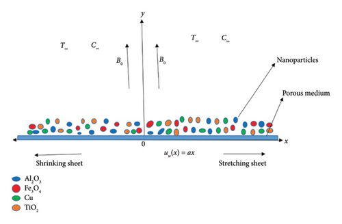
This study considers a steady 2D laminar boundary layer MHD flow of a biviscous Bingham tetra nanoparticle over a permeable stretching/shrinking sheet. The nanoparticle is composed of Al2O3, Fe3O4, TiO2, and Cu in a water-based fluid. The velocity of the sheet is uw(x) = ax. The flow is restricted to y > 0. Fluid moves in a path perpendicular to the direction in which magnetic force B0 is applied. The coordinates (x, y) are employed so that x is along the sheet surface and y is considered to be perpendicular to it. Figure 1 portrays a simplified schematic depiction of the fluid flow. The problem incorporates the magnetic field, permeable medium, heat generation/absorption, viscous dissipation, concentration, and chemical reaction effects. The far temperature and concentration at the walls are T∞ and C∞, respectively.
In the above equation, py is the yield stress of the biviscous Bingham fluid, μb is the plastic dynamic viscosity, π = eij and eij denote the (i, j)th element of deformation rate, and πc is the critical value of this product based on the non-Newtonian model.
For tetra nanoparticles, we interpret the expression as νtetra(1 + (1/β))(∂2u/∂y2).
The main leading flow equations, constructed in the usual notation [17, 36, 52–54], are as follows.
2.2. Conversion of Leading Equations
Mathematical models of thermophysical properties of advanced tetra hybrid nanoparticles are depicted as follows [17, 18, 28].
Here, , and σf are forceful dynamic viscosity, density, heat capability, thermal conductivity, and electrical conductivity of the base fluid. ρs1, ρs2, ρs3, and ρs4, , κs1, κs2, κs3, and κs4, σs1, σs2, σs3, and σs4 are the densities, capacities, heat conductivities, and electrical conductivities of the used nanoparticles. ϕ1, ϕ2, ϕ3, and ϕ4 are the solid volume fractions of the first, second, third, and fourth nanoparticles.
3. Analytical Procedure
3.1. Solution for Momentum
It should be noted that because the square roots may provide complex values, the solutions provided in equations (27) and (28) may or may not exist based on the values of the pertinent physical parameters. Note that, according to α2, there is only one solution for d > 0. Moreover, for d < 0 given by the α4, there is another solution that arises.
3.2. Solution for Energy
For both PST and PHF cases, equations (48) and (49) provide exact solutions for the energy equation.
3.3. Solution for Mass
In this part, we achieved an exact solution for both energy and mass equations in terms of hypergeometric function. Move on to the next part, where we have to discuss the present issues and their results.
4. Graphical Description
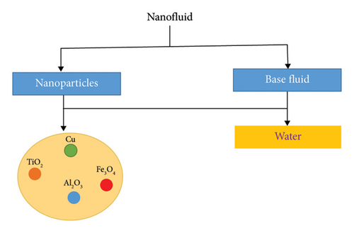
In this work, we utilized the four different types of nanoparticles (Al2O3+Fe3O4+TiO2+Cu/H2O) in base fluid H2O that flows over a permeable stretching/shrinking sheet with a slip model. In the analytical inspection of the present mathematical model, we deliberated the impression of controlled dimensionless parameters on innumerable values on and θ′(0) displayed through graphically. The primary goal of the present study is to explore the use of THNF to boost the thermal transfer rate. It has been observed that THNF is more efficient for improving the rate of heat transfer. The thermophysical characteristics of the H2O and present nanoparticles are provided in Table 1, where the Prandtl number of the base fluid is kept at 6.2. We adopt constant values for the controlling parameters throughout the computation: 0.01 ≤ ϕ1 + ϕ2 + ϕ3 + ϕ4 ≤ 0.1, 0.5 ≤ M ≤ 24, −1 ≤ Vc ≤ 2, 0.1 ≤ β ≤ 2, −1.5 ≤ λ1 ≤ 1, −3 ≤ λ2 ≤ 1, 0.1 ≤ Da−1 ≤ 2, 0.1 ≤ Nr ≤ 0.4, 0.1 ≤ Ec ≤ 4, 0.2 ≤ Sc ≤ 4, 0.02 ≤ K ≤ 10, 0.1 ≤ λ ≤ 4, and −0.37 ≤ Q ≤ 0.37 are employed to achieve the desired accuracy and convergence. The preparation of tetra nanoparticles is shown in Figure 2.
| Properties | Water | Al2O3 | Fe3O4 | TiO2 | Cu |
|---|---|---|---|---|---|
| Density ρ(kgm−3) | 997.1 | 3970 | 5180 | 4250 | 8933 |
| Specific heat (Jkg−1K−1) | 4180 | 765 | 670 | 686.5 | 385 |
| Heat conductivity (Wm−1K−1) | 0.613 | 40 | 9.7 | 8953 | 401 |
| Electrical conductivity (Ωm)−1 | 5.5 × 10⁶ | 5.96 × 10⁷ | 2.5 × 10⁻⁴ | 2.6 × 10⁶ | 5.96 × 10⁷ |
| Prandtl number Pr | 6.7 | — | — | — | — |
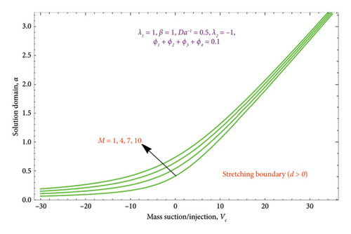
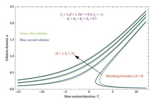
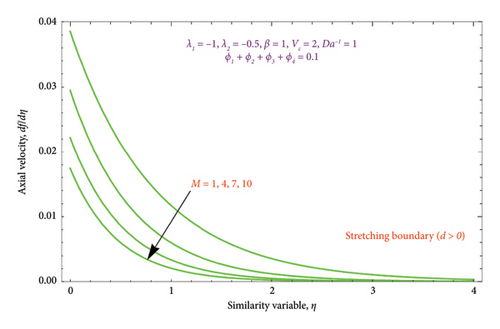
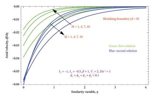
The region of solution for α and the consequence of magnetic strength M are shown in Figures 3(a) and 3(b), which depict the d > 0 and the d < 0, respectively. Raising M influences the value of α to rise as well. Additionally, as predicted by equation (20), there are several solutions for d = −1 and a unique solution for d = 1, and the area of multiple solutions spreads as M grows. Figures 4(a) and 4(b) demonstrate the key characteristics of magnetic number M on the velocity profile. For d > 0, it is observed in Figure 4(a) that as the velocity component declines, it enhances the magnetic number M. Physically, due to the presence of a magnetic field, an opposing sort of force (such as Lorentz force) will be developed in the nanoparticle flow. This force tends to lower the nanoparticle velocity. Figure 4(b) is drawn to witness the effect of M on dimensionless velocity profile (df/dη). Curves indicate that the strength of the (df/dη) in the first solution expands as the entities of M rise; however, in the second solution, they behave oppositely.
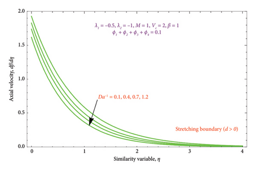
Figures 5(a) and 5(b) are drawn to analyze the upshot of Da−1 on the velocity profile (df/dη). For d > 0, it is noted from Figure 5(a) that the magnitude of the Da−1 rises by lowering the fluid velocity. It happens because there is a porous medium in the flow field, which retards the fluid velocity more and, as a result, thins the boundary layer. Similarly, from Figure 5(b), it can be seen that dimensionless velocity increases by increasing the strength of the Da−1 in the first solution. The second solution shows the opposite behavior. As the Da−1 parameter rises, decreasing velocity profiles and BL are seen. This could be because of the incorporation of nanoparticles into the biviscous Bingham fluid and the resistance force of the porous matrix, which will slow down the flow.

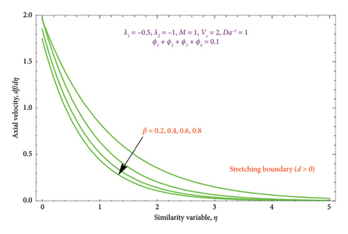
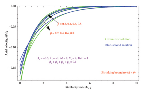
Figures 6(a) and 6(b) depict the performance of the biviscous Bingham fluid parameter β on the velocity profile for both cases of d > 0 and d < 0. It is evident from Figure 6(a) that rises in quantity of β lowers the thickness of BL. As a result, the nanoparticle movements decelerate away from the surface, resulting in a thinner BL as β rises. The dual character of the solution for various values of β is displayed in Figure 6(b). For the second solution, it is found that the BL thickness of the velocity function falls gradually as the Bingham parameter rises, but for the first solution, it exhibits a slightly rising behavior.
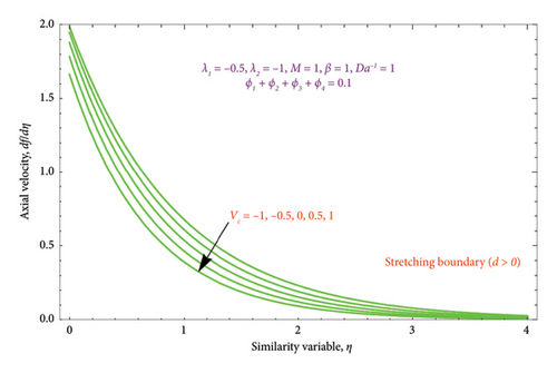
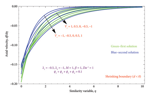
Figures 7(a) and 7(b) are constructed for the variation of the mass suction/injection parameter Vc on the dimensionless velocity profile. Figure 7(a) shows that the nature of the flow velocity declines when the strength of the Vc rises. As a result, the low pressure at the inlet face permits liquid to pass through the media. This is because elevated Vc parameters affect both the BL and momentum BL thicknesses. The suction Vc = 0.5, 1 depicts the thinner effect, whereas Vc = −1, −0.5 signifies the thicker effect on velocity. Figure 7(b) displays the dual nature solution for variation of Vc on the velocity profile. It is observed that the BL thickness of velocity has slight deceleration with improving the Vc values in the first solution, whereas the BL thickness of the velocity function reveals a sharp acceleration in Solution 2.
Figures 8(a) and 8(b) and 9(a) and 9(b) are plotted to analyze the effects of the first-order λ1 and second-order λ2 slips on the velocity profile. From Figures 8(a) and 9(a), it can be easily noticed that the nanoparticle velocity reduces when entities of |λ1| and |λ2| escalate. Hence, the hydrodynamic BL diminishes. In turn, there is a decline in local velocity. The phenomenon occurs because of the physical nature of surface slip, which results in higher slip attendance and lower fluid penetration of the d > 0. Moreover, Figure 8(b) reveals that rising values of |λ1| resulted in a reduction in the momentum BL thickness and velocity profile for both solutions. Finally, the dual velocity profile for several values of |λ2| is displayed in Figure 9(b). It is observed from Figure 9(b) that the BL thickness rises with enhancing the |λ2| values for the first solution. In contrast, the second solution demonstrates the crossing over as it climbs with |λ2|.
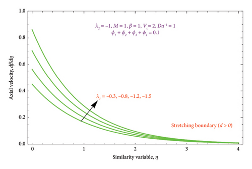
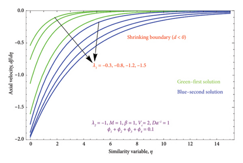
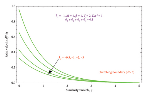
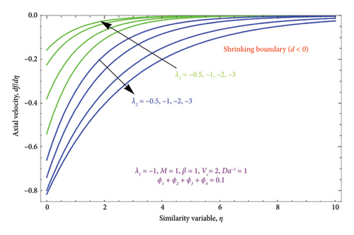
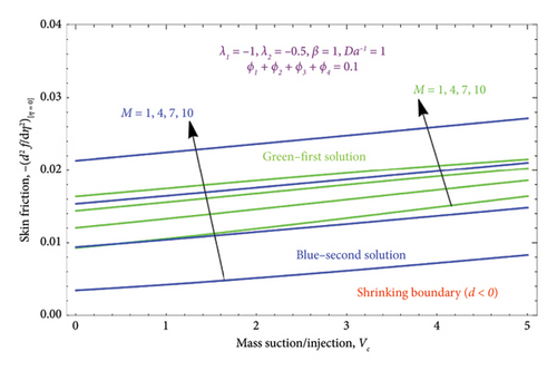
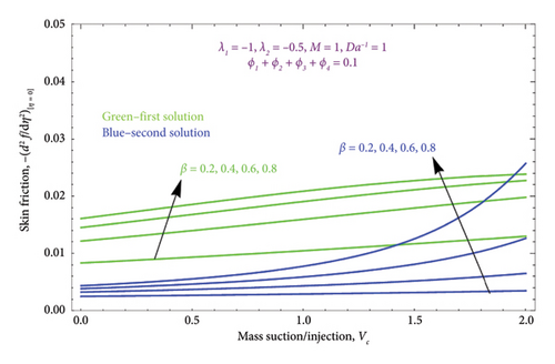
Figure 10 displays the variation of the skin friction profile versus suction/injection parameter Vc for several values controlling parameter M when d < 0. It depicts that the magnitude of the skin friction profile is directly proportional to the M; when M enhances, it also improves the magnitude of the skin friction profile in both solutions. Moreover, Figure 11 is drawn with various values of the biviscous Bingham parameter β on the skin friction profile, while other parameters are kept fixed. From this figure, we observed a massive enhancement in values of β, which enhances the skin friction profile.
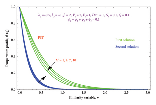
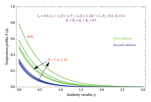
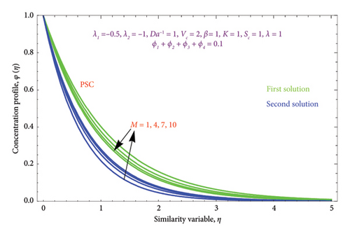
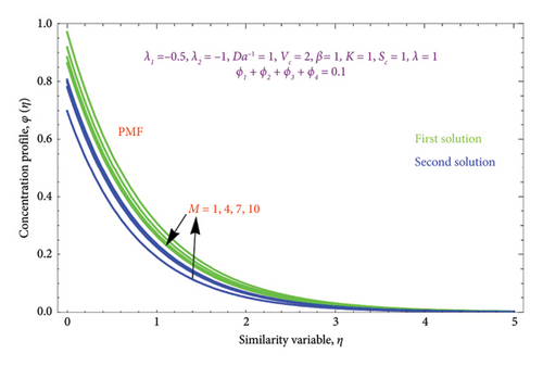
Figures 12(a) and 12(b) and 13(a) and 13(b) illustrated the variation of M on θ(η) with PST and PHF conditions as well as φ(η) profile along with PSC and PMF, respectively, while other parameters are kept fixed. It is seen from Figure 12 that the magnitude of the M escalates with rises in the θ(η) profile in the second solution of both conditions. This can be attributed to the fact that the extra energy needed to move the fluid against the M, which allows the fluid’s temperature to increase. As demonstrated in Figures 12(a) and 12(b) of both BCs, the work is turned into heat energy, which heats the liquid and advances the thermal BL thickness, while the reverse effect occurs in the first solution. Furthermore, we see a growing trend in φ(η) profile by uplifting the values of M in the second solution, whereas the opposite trend was observed in the first solution as exhibited in Figures 13(a) and 13(b).
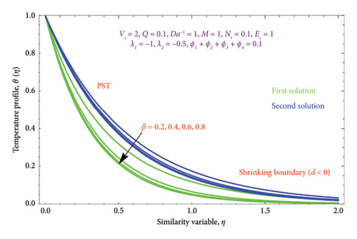
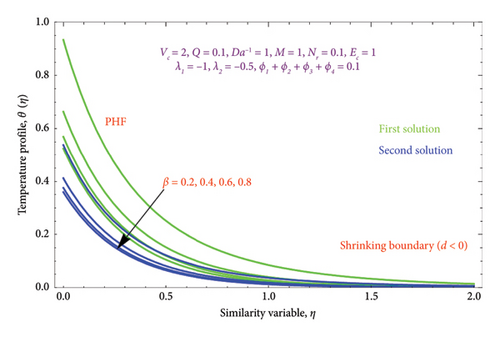
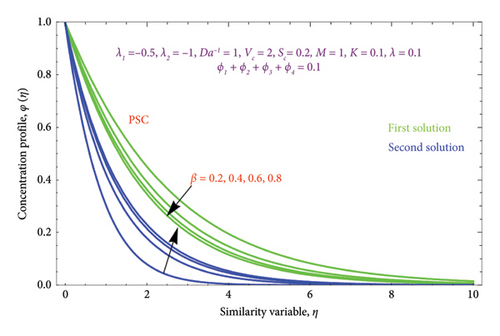
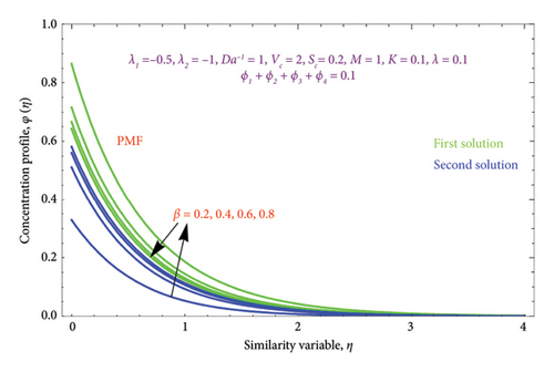
Figures 14(a) and 14(b) and 15(a) and 15(b) reveal the characteristics of β on θ(η) and φ(η) profiles. From Figures 14(a) and 14(b), it is noted that the θ(η) profiles are belittled for incrementing the values of the β. The (Al2O3–Fe3O4–TiO2–Cu/H2O) Bingham nanoparticles yield stress strength that degrades with raising β values, which in turn improves the plastic dynamic viscosity and, as a result, reduces the thickness of the thermal BL in both solutions. Here, we report that the thermal BL thickness of the Bingham tetra nanoparticles is higher than that of the Newtonian liquid. It can be observed that the Bingham tetra nanoparticles behave like a Newtonian liquid when the β (β⟶∞) increases. Consequently, lowering stress boosts fluid flow and diminishes heat transmission. Enhancement in the values of the β reduces the thickness of the φ(η) profile in the first solution, while opposite effects as observed in the second solution are displayed in Figures 15(a) and 15(b).
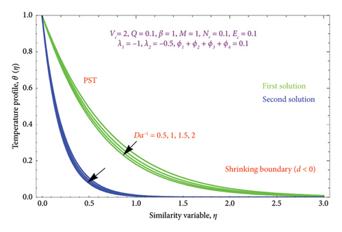
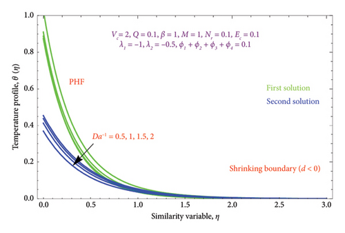
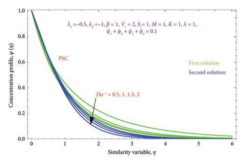
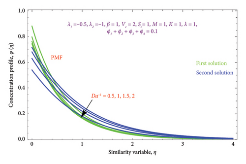
Figures 16(a) and 16(b) and 17(a) and 17(b) present with different values of Da−1 on θ(η) and φ(η) profiles, accordingly. From these figures, it is found that as the Da−1 rises, the fluid temperature and concentration fall in both solutions. This is because a resistive force induced by the Da−1 drops the fluid’s thermal diffusivity and concentration. It indicates an upsurge in the permeable structure of the pores.
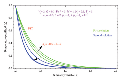
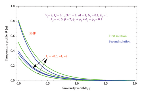
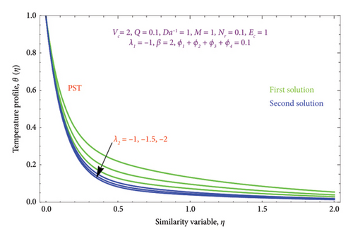
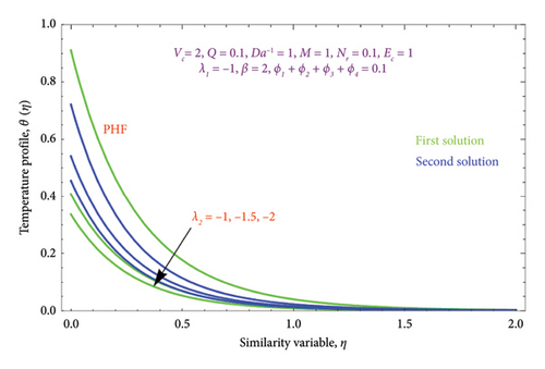
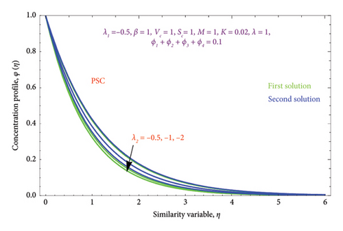
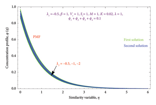
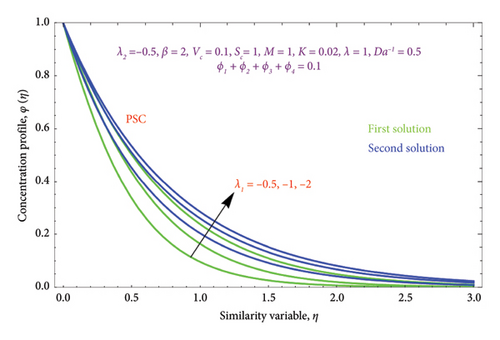
Figures 18(a) and 18(b) and 19(a) and 19(b) interpret the influence of first-order λ1 and second-order λ2 slips on θ(η) profile, respectively. From Figures 18(a) and 18(b), we detect an accelerating value of |λ1| with an increment in thermal BL thickness in the first solution, whereas reverse impact occurs in the second solution. It can be clearly examined that dimensionless thermal and concentration fields declined by raising the values |λ2| enlightened in Figures 19(a) and 19(b) and 20(a) and 20(b). The upsurges in quantities of first-order slip |λ1| with enhancing the thickness of the φ(η) profile are interpreted in Figures 21(a) and 21(b).
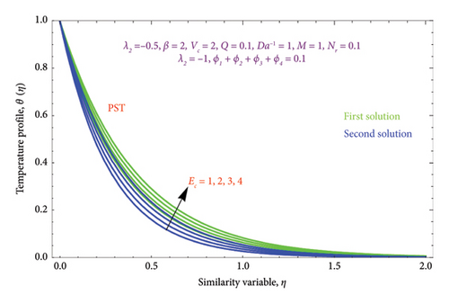
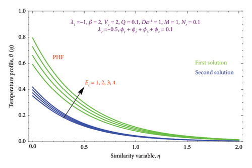
Figures 22(a) and 22(b) are plotted to know the essence of Ec on θ(η) profile for both PST and PHF conditions. We see that the ascending values of the Ec number boost the thermal field in the porous regime in both solutions. The Ec reflects the amount of mechanical energy that turns into heat energy, or heat dissipation, through internal friction. As a result, rising Ec values will result in more thermal energy entering the flow and heating the regime. There is a noticeable temperature overshoot close to the wall for all nonzero values of Ec; as Ec rises, this overshoot somewhat moves into the BL.
Figures 23(a) and 23(b) are sketched to know the characteristics of Sc on φ(η) profile for both scenarios of PSC and PMF conditions. As the Sc rises, the solute diffusivity decreases, allowing the solutal action to penetrate the solution relatively shallower. Consequently, as Sc expands, the concentration diminishes in both solution branches. Therefore, for lower concentrations of Sc, the solute BL is thicker and vice versa. Figures 24(a) and 24(b) are prepared to demonstrate the effect of heat source/sink Q parameter on θ(η) profile with cases PST and PHF. It is noticed from Figure 24 that the temperature field grows as Q rises in both solutions. Growing Q really allows the thin film’s kinetic energy to escalate, which boosts internal heat.
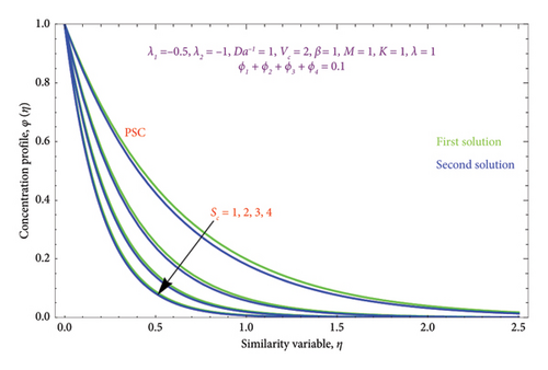
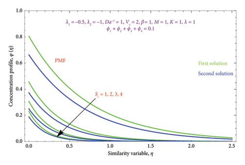


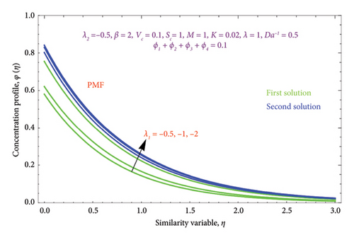
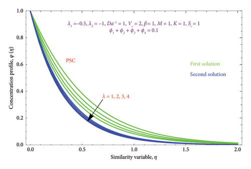
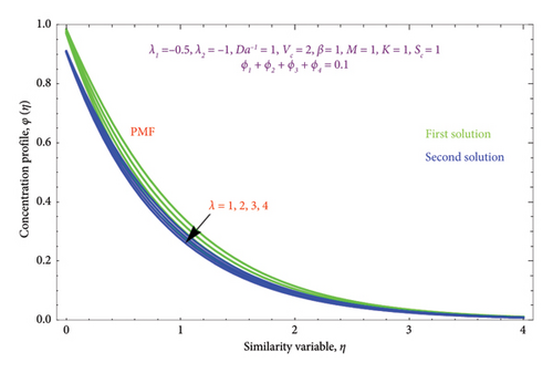
Figure 25 depicts the effect of λ on φ(η) profile with PSC and PMF cases. It is evident from the figure that the φ(η) profile and the λ parameter are inversely related in both solutions. Physically, when λ > 0, it indicates that mass is moving outward from the porous stretched sheet and into the surrounding area.
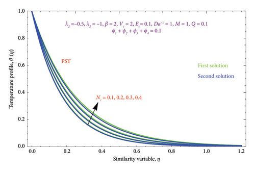
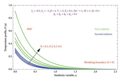
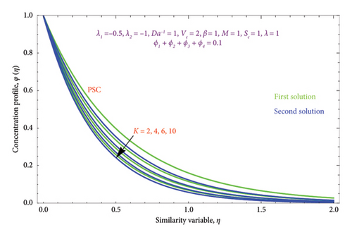
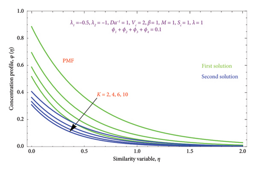
Figures 26(a) and 26(b) are plotted to perceive the impact of Nr on θ(η) profile with PST and PHF conditions. The figure indicates that there is a growing impression of Nr on θ(η) in both solutions. It is well known that the process of radiation and heat transmission generates energy through fluid particles, leading the flow to produce more heat. It is noteworthy to emphasize that the impact of radiation increases with Nr⟶∞ and can be neglected when Nr = 0. The inclusion of the chemical effect parameter K on φ(η) profile is illustrated in Figures 27(a) and 27(b) with PSC and PMF conditions. It has been shown that concentration declines as the chemical reaction K grows in both solutions. This is valid since chemical molecule diffusivity diminishes with greater K values.
5. Final Remarks
- •
For the d < 0, two solutions are found.
- •
For d > 0, an upsurges in magnitude of M, Da−1, β, Vc, |λ1|, and |λ2| yield declines in (df/dη) profile and increment in M and β values with increases in profile.
- •
For d < 0, an enrichment in strength of M, Da−1, β, Vc, and |λ2| is observed in the first solution, whereas opposite trends are observed in the second solution of the (df/dη) profile. While |λ1| goes up, it reduces the thickness of momentum BL in both solutions.
- •
The growth in M and β enhances the θ(η) and φ(η) BL thicknesses in the second solution, whereas a reverse criterion is observed in the first solution, while Da−1 value rises with a decline in the θ(η) and φ(η) profiles in both solution branches.
- •
In θ(η) profile, the upward trend is observed in Ec, Q, and Nr quantities with improvement in θ(η). BL is thicker in PST than PHF, whereas φ(η) reduces with increases in entities of Sc, λ, and K in both PSC and PMF conditions.
| Related works by other authors | Fluids | Value of α |
|---|---|---|
| Maranna et al. [26] | Non-Newtonian | f(η) = A + B exp(−αη), |
| A = Vc + (d/α + λ1α2 − λ2α3), with B = (−d/α + λ1α2 − λ2α3), α4 − pα3 + qα2 + rα + t = 0 | ||
| Sadighi et al. [58] | Non-Newtonian | |
| Present work | Non-Newtonian | f(η) = Vc + d((1 − e−αη)/α(1 + λ1α − λ2α2)), ξ1α4 − ξ2α3 − ξ3α2 + ξ4α + ξ5 = 0 |
- •
{Results present work}⟶{Results of Sadighi [58]}.
Nomenclature
-
- a
-
- Constant
-
- A, A1, A2
-
- Constants
-
- b0, b1, b2
-
- Constants
-
- B0
-
- Magnetic field Am−1
-
- C
-
- Concentration function
-
- Cw
-
- Wall concentration
-
- C∞
-
- Ambient concentration
-
- Da−1
-
- ( = μf/ρfKa) Inverse Darcy number
-
- Ec
-
- Eckert number
-
- f
-
- Dimensionless function
-
- H
-
- Hypergeometric function
-
- h1, h2
-
- Constants
-
- K
-
- Permeability (N/A2)
-
- Kc
-
- ( = (K∗/a)) Chemical reaction parameter (mol/s)
-
- k∗
-
- Mean absorption coefficient (m/s3)
-
- k
-
- Constant
-
- M
-
- Magnetic field (kgm−1s−1A−1)
-
- m, m1, n, n1
-
- Constants
-
- Nr
-
- Radiation parameter m2s−3
-
- Pr
-
- Prandtl number
-
- qr
-
- Radiative heat flux (kgm2s−3)
-
- Q
-
- Heat generation/absorption
-
- p, q
-
- Constants
-
- T
-
- Fluid temperature K
-
- Tw
-
- Wall temperature K
-
- T∞
-
- Far temperature K
-
- Sc
-
- ( = (νf/D)) Schmidt number
-
- S1, S2, S3, S4
-
- Constants
Greek symbol
-
- α
-
- Solution domain
-
- ξ, ξ1, ξ2, ξ3, ξ4
-
- Constants
-
- ζ
-
- Constants
-
- μf
-
- Dynamic viscosity (kg/ms)
-
- ρf
-
- Density of base fluid (kg/m3)
-
- σf
-
- Electrical conductivity (S/m)
-
- σ∗
-
- Stefan–Boltzmann constant (Wm−2K)
-
- κf
-
- Thermal conductivity (W/mK)
Abbreviations
-
- PDEs
-
- Partial differential equations
-
- ODEs
-
- Ordinary differential equations
-
- MHD
-
- Magnetohydrodynamics
-
- nf
-
- Nanofluid
-
- tnf
-
- Ternary nanofluid
-
- THNFs
-
- Tetrahybrid nanofluids
-
- NN
-
- Non-Newtonian
-
- BL
-
- Boundary layer
-
- PST
-
- Prescribed surface temperature
-
- PHF
-
- Prescribed heat flux
-
- PSC
-
- Prescribed surface concentration
-
- PMF
-
- Prescribed mass flux
Conflicts of Interest
The authors declare no conflicts of interest.
Funding
This work was funded by the National Research Foundation of Korea (Grant Number NRF2022-R1A2C2002799). The work of the author H. N. Huang is partially supported under Grant No. MOST 110-2115-M-029-002 and nice hospitality.
Acknowledgements
This work was funded by the Grant NRF2022-R1A2C2002799 of the National Research Foundation of Korea. The author T. Maranna acknowledged the financial assistance received from the Karnataka Science and Technology Society (KSTePS) under the program of Karnataka DST-Ph.D. Fellowship for Science and Engineering: DST/KSTePS/Ph.D. Fellowship/MP-07:2023-24. The work of the author H. N. Huang was partially supported under Grant No. MOST 110-2115-M-029-002 and nice hospitality.
Open Research
Data Availability Statement
Data that support the findings of this study are available from the corresponding authors upon reasonable request.


